Collision Avoidance Software (CAS)
Overview
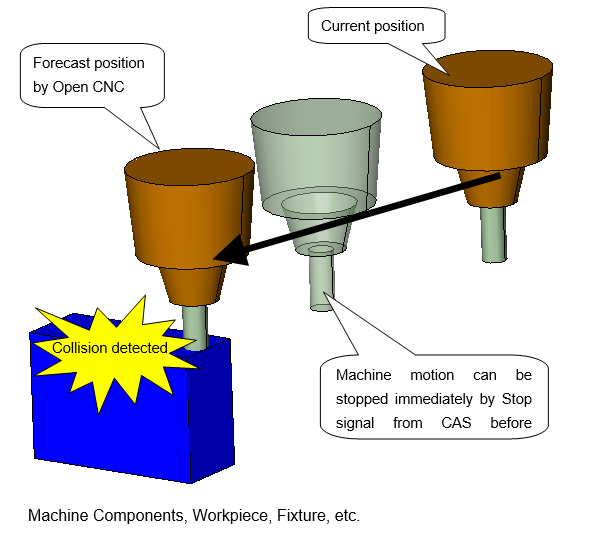
Collision Avoidance Software (CAS) detects potential machine collisions in real time and stops the NC Control before impact occurs. It connects an external PC to a FANUC 30-Series NC Control via HSSB optical fiber, and uses forecast position data from the control to run cutting and machine simulations continuously during machining.
CAS maintains 3D models of the machine, tools, fixtures, and workpiece. When a collision is detected, a stop signal is sent to the NC Control immediately. The operator can then move the affected axis manually — only in the direction away from the collision.
CAS has three operating modes:
| Mode | What It Does |
|---|---|
| 3D Check | Full collision detection and cutting simulation running. Primary production mode. |
| Monitor | Cutting simulation only — no collision detection. Used for setup review. |
| Edit | Configure tools, fixtures, and stock. No simulation running. |
Requirements
- NC Control: FANUC 30i-A, 31i-A, 31i-A5, 300is-A, 310is-A, or 310is-A5 only
- Connection: HSSB optical fiber (FOCAS2/Ethernet is not supported)
- OS: Windows XP Professional (32-bit)
- Graphics memory: 128 MB minimum; 256 MB recommended
- Processor: Intel Pentium 1 GHz or faster
CAS connects to one NC Control at a time only.
Hardware and software installation is performed by your machine tool builder (MTB) at the time of machine delivery. Contact your MTB for installation and configuration support.
Workflow
Step 1 — Launch CAS
CAS can be set to launch automatically when the PC powers on, or started manually from the Program menu. It opens the last-used Project file automatically.
To start a new job, choose from the Project Tree:
| Option | Use When |
|---|---|
| Resume | Continuing the previous session |
| Open Project | Loading a saved CAS Project |
| New Project | Starting a fresh setup |
| VERICUT Project | Opening a project built offline in VERICUT |
Step 2 — Set Up in Edit Mode
All fixture, stock, and tool setup is done in Edit Mode. Machine models are pre-configured by MTB at delivery.
Register a Fixture
- Click Fixture in the Project Tree.
- Right-click and select Add Model.
- Choose a primitive (block, cone, cylinder), use the Sketcher, or import a SAT/IGES/STL file.
- Position the model to match the actual machine location.
- Use Adjust Fixture Position (M703) from the NC Control panel to align automatically.
Register Stock
- Click Stock in the Project Tree.
- Right-click and select Add Model.
- Add geometry the same way as Fixture.
- Use Adjust Stock Position (M704) from the NC Control panel to align automatically.
CAS supports one Fixture and one Stock component. Do not add or delete Component nodes.
Register Tools
- Double-click Tooling in the Project Tree to open Tool Manager.
- Open or create a Tool Library file.
- Right-click in the Tool Table and select Add.
- Build assemblies from: Flat/Ball/Bull Nose End Mills, Drills, General Inserts, and Block/Cone/Cylinder holders.
- Use Milling Tool Wizard for quick setup — pre-installed MST and BIG holder libraries are available.
- Use Adjust Tool Length (M702) from the NC Control panel to sync tool offsets from the control.
- Save via File > Save.
Probe tools are configured to not trigger collision when contacting the workpiece.
Set Cutting Tolerance
In the Project Tree, go to Cutting Tolerance and set the simulation accuracy. The near-miss threshold under Machine Settings > Collision Detect is set by MTB at delivery and does not normally need operator adjustment.
Save the Project
Use File > Save Project before switching modes.
Step 3 — Run Collision Detection (3D Check Mode)
- Confirm the NC Control is on and the HSSB connection is active.
- Enable collision detection from the NC Control panel (M701 ON).
- Switch CAS to 3D Check Mode.
CAS polls the NC Control for forecast positions in real time, updates the cut stock model, and checks all 3D models for interference. If a collision is detected, the NC Control is stopped immediately.
No GUI interaction is available in 3D Check Mode except switching to Monitor Mode.
Step 4 — Monitor Mode (Optional)
Switch to Monitor Mode to watch cutting simulation without collision detection active — useful for setup verification or reviewing an operation in progress.
The resulting cut stock can be saved as a VERICUT Solid and used as the starting stock for a subsequent operation.
Step 5 — Close CAS
Click the [Close] button on the status display window.
Save CAS File
Location:
Utilities tab >  (Save CAS File)
Save CAS File
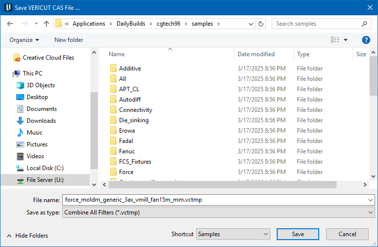
The Save CAS File command button opens the Save Vericut CAS File file selection window, enabling you to save CAS files.