Control Settings window
Location:
Machine/Control tab >  (Control Settings)
Toolbar short cut: ![]()
The Control Settings command button opens the Control Settings window enabling you to configure how the machine control will process machine code data.
General tab — Features on this tab are used to configure general guidelines for how the control processes machine code data and number equations.
Motion tab — Features on this tab are used to configure default NC control motion states, and the precision used when outputting calculated values.
Circles tab — Features on this tab are used to configure how the circle center data (e.g. I J K) is interpreted.
Cycles tab — Features on this tab are used to configure how fixed tool axis, or "canned" cycle motion blocks are interpreted, e.g. G8n.
Tooling tab — The features on this tab are used to configure default tooling conditions and tool change activity.
Rotary tab — Features on this tab are used to configure how rotary motion commands are interpreted, e.g. A, B, C.
Cutter Compensation tab — Features on this tab are used to configure how the programmed tool path is compensated when cutter diameter compensation, or "CDC" is used, e.g. G41-42.
Offsets tab — Features on this tab are used to configure an initial work offset, or “fixture offset”, to be in effect at the start of tool path processing.
Subroutines tab — Features on this tab are used to configure how subroutine names are referenced by the NC control.
Channels tab — Features on this tab configure Vericut for simulating machining with synchronized subsystems.
Turning tab — Features on this tab configure Vericut for lathe turning simulations.
OK — Applies the changes and closes the Control Settings window.
Apply — Applies the changes and leaves the Control Settings window open.
Cancel — Closes the Control Settings window without applying changes.
To learn more about how Vericut processes G-Code data, see "About Building NC Controls" in the Building NC Controls group section of Vericut Help.
Control Settings window, General tab
Locations:
achine/Control tab >  (Control Settings)
Optimize tab >  (Optimize Control) > G-Code Output Options tab
Toolbar short cut: ![]()
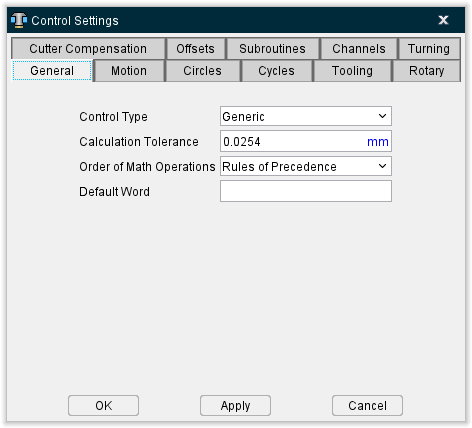
The features on the General tab enable you to configure general guidelines for how the control processes machine code data and number equations.
Control Type — Sets the type of NC control being used. Choosing the proper option establishes a mode of operation consistent with how the control processes NC data. Options are:
-
Generic — Fanuc and most other controls using standard controller functions.
-
NUM — French-made control. This option affects how G-Code data is interpreted, for example: how variables are initialized and processed, and how to interpret parameters to macros that shift the location of the tool path.
-
Heidenhain Conversational — Heidenhain Conversational control. This option causes Vericut to recognize the "L" word as an optimizable word. Also, the "L" word is included with any cuts added during optimization.
-
Siemens — Siemens 840D control. Special logic is added in the "filter" logic for the processing of NURBS.
-
Toshiba — Toshiba control. Special logic is added in the "filter" logic for the processing of NURBS.
-
*Heidenhain ISO — Heidenhain ISO control. If a block is marked as non-optimizable, and the block contains a I, J, or K (circle record), then the Feedrate is not restored (similar to going into RAPID mode). A series of Optimization output formatting decisions are based on this control type.
-
K&T — Kearney & Trecker control. Special handling is added for TYPE II processing. If a TYPE II argument is defined to be a V (Value), but an "=" character is found within this argument, then the argument is internally processed as a WV argument.
-
Okuma OSP — Use for Okuma controls to invoke special logic to handle the following situations:
-
CALL OSUB1 (a call to a subroutine)
- OSUB1 (the declarations of a subroutine)
- IF (expression) NLABEL1 (a branch to a label)
- NLABEL1 (the declaration of a label)
-
Local Variables – which can be used without being defined
-
Special handling of variables being assigned to “EMPTY”.
-
Thermwood — On a Thermwood control, you can have statements like:
SET ABC=5
[BCD = 7]
[ABC$ = “DAVE”)
If the variable being set does not exist, the variable and the corresponding word will be created.
A variable ending with a ‘$’ contains a text value. All other variables contain numeric values.
For the above to be correctly processed, the control type must be set to Thermwood.
These situations previously often resulted in “Error: The Word xxxx is not defined” error messages.
Calculation Tolerance — Tolerance for rounding mathematical evaluations, such as determining if two calculated values are equal to, greater than, or lesser than each other.
📝 NOTE: The Calculation Tolerance should be adjusted to eliminate "invalid circle" errors caused by circle calculations that produce differences larger than the tolerance value when processing G-Code data.
Order of Math Operations — Order in which math operations are performed. Options are:
-
Rules of Precedence — Follow the basic rules of math precedence:
-
Perform exponential (power).
-
Perform multiplication and division operations.
- Perform addition and subtraction operations, example: 5 + 5.3 * 3 * sin(30)= 12.95
Enclosing math operations in parenthesis causes them to be performed before those not enclosed in parenthesis. The same rules of precedence are applied to math operations enclosed in parenthesis.
Left to Right — Use left to right sequence, example: 5 + 5.3 * 3 * sin(30)= 15.45
Default Word — Word assumed by Vericut for NC data blocks beginning with numbers, such as NC data for some Heidenhain controls. For example, for Vericut to interpret blocks like "50G01X5", set Default Word to "N". Vericut then interprets the block without error as "N50G01X5".
See Configuring "General" NC Control Settings, in the Using the Control Settings window section, also in the Machine/Control tab section of Vericut Help for additional information.
See Variables, Control panel, also in the Project Tree section of Vericut Help for information on adding Variables to a control configuration.
Control Settings window, Motion tab
Location:
Machine/Control tab >  (Control Settings)
Toolbar short cut: ![]()
The features on the Motion tab enable you to configure default NC control motion states, and specify the precision used when outputting calculated values. These settings are in affect when the control and machine are initially powered on.
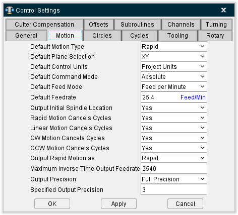
Default Motion Type — Default motion type for the control. Options are:
-
Rapid
-
Linear
Default Plane Selection — Default motion plane, or "cutting plane" for the control. Options are:
-
XY
-
ZX
-
YZ
Default Control Units — Default measurement units for the control. Options are:
-
Project Units (the units specified in the .VcProject file)
-
Inch
-
Metric
Default Command Mode — Default command mode, or "input dimension mode" for the control. Options are:
-
Absolute
-
Incremental
Default Feed Mode / Default Feedrate — Default feed rate mode and value for the control. Options are:
-
Feed per Minute
-
Feed per Revolution
Output Initial Spindle Location — When active (Yes), causes the machine to move to its initial spindle location at the beginning of NC program processing. Enter initial machine location values in an Initial Machine Location table.
Rapid Motion Cancels Cycles — When active (Yes), rapid motions (e.g. G0) cancel canned cycles (e.g. G81-89).
Linear Motion Cancels Cycles — When active (Yes), linear motions (e.g. G01) cancel canned cycles (e.g. G81-89).
CW Motion Cancels Cycles / CCW Motion Cancels Cycles — When active (Yes), clockwise (or counterclockwise) circular interpolation motions (e.g. G02) cancel canned cycles (e.g. G81-89).
Output Rapid Motions as — Controls the format in which rapid motions are written to the APT Output file during reverse post-processing. Options are:
-
Feedrate — Outputs a "FEDRAT/n" command where the feed rate is calculated based on the rapid priority of moving axes, and then output the tool tip location(s). When rapid priority causes axes to move independently, multiple tool tip positions are output.
-
Rapid — Outputs the word "RAPID" followed by a single tool tip location.
Maximum Inverse Time Output Feedrate — Highest feedrate value which can result from interpreting inverse time feed rate values (e.g. G93). The output feed rate is set to this rate when in inverse time feed mode and the calculated feed rate is zero or greater than the specified maximum.
-
Output Precision — Controls the accuracy used to interpret calculated values, such as: CDC offset positions, mathematical operations, etc. Options are:
-
Full Precision — Highest possible accuracy. Note that full precision output values can result in higher accuracy than the NC control uses, which may result in differences between simulated motion and the actual motion performed by the NC control.
-
Specified Precision — Use the accuracy specified via the Specified Output Precision feature (see below).
Input Precision — Use the accuracy used in the input NC program file. For example, when NC program file data is in 3.4 format, the precision used is also 3.4.
Specified Output Precision — When Output Precision = Specified Precision, this value reflects the accuracy used by the NC control to perform the operations described above for Output Precision.
See Configuring "Motion" NC Control Settings, in the Using the Control Settings window section of Vericut Help for additional information.
Control Settings window, Circles tab
Location:
Machine/Control tab >  (Control Settings)
Toolbar short cut: ![]()
The features on the Circles tab enable you to configure how the circle center data (e.g. IJK) is interpreted. The Interpolation Tolerance determines the quantity of machine positions which simulate arc and helical motions.
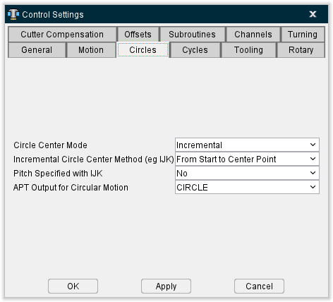
Circle Center Mode — Mode in which to interpret circle center data. Options are:
-
Absolute — Absolute center coordinates.
-
Incremental — Incremental distances. (See "Incremental Circle Center Method" below).
-
G Code Dependent — As described above, except depends on the active input dimension mode: absolute or incremental.
Incremental Circle Center Method — When interpreting incremental circle center values, this feature controls how incremental circle center data is interpreted. Options are:
-
From Start to Center Point — Distance from circle start point to circle center.
-
From Center to Start Point — Distance from circle center to circle start point.
-
Unsigned — Unsigned, positive incremental distance between circle start point and circle center). Unsigned incremental circle motion blocks are always positive in value, and do not cut circles greater than 90 degrees.
Pitch Specified with IJK — This option determines if the CircleCenterX, and CircleCenterY, and CircleCenterZ macros can be used to determine the pitch. Only the macro which corresponds to the direction perpendicular to the current motion plane will be used for the pitch value. The pitch is defined as depth per revolution. The default is "No". If set to "Yes", the delta depth distance is divided by the pitch to determine the number of full loops. If set to "No", the HelicalFullLoops macro should be called, and the pitch will be calculated based on the number of full loops, the delta depth distance, and the starting and ending angles.
APT Output for Circular Motion — Controls the format in which circular motions are output during conversion to an APT output file. Options are:
-
CIRCLE
-
CIRCLE and GOTO’s
-
GOTO’s
An APT Output file is created when the Create APT Output File (Ref. Process Options window: G-Code Output Files tab in the Vericut Project Tree section of Vericut Help) is toggled on (checked).
See Configuring "Circles" NC Control Settings, in the Using the Control Settings window section of Vericut Help for additional information.
Control Settings window, Cycles tab
Location:
Machine/Control tab >  (Control Settings)
Toolbar short cut: ![]()
The features on the Cycles tab enable you to configure how fixed tool axis, or "canned" cycle motion blocks are interpreted, e.g. G8n.
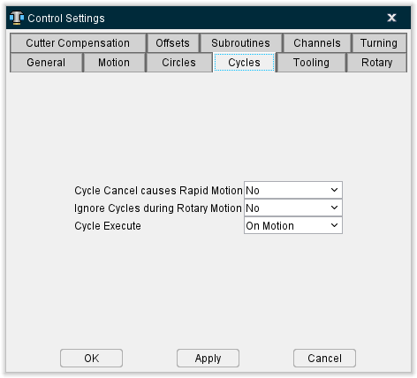
Cycle Cancel causes Rapid Motion — When active (Yes), sets the rapid motion mode with a cancel cycle command (e.g. G80).
Ignore Cycles during Rotary Motion — When active (Yes), canned cycles are ignored during rotary motions. Set to No to allow processing of canned cycles during rotary motions. The use of this modal becomes more important when the Output Intermediate Points feature on the Control Settings window: Rotary tab, is active.
Cycle Execute — Controls when cycle motions are executed. Options are:
-
On Motion — Execute cycle on cycle block and each following motion until cancelled. (Default)
-
As Commanded — Cycle definition block is for setup only; execute cycle when commanded by a specific word/address, such as G79 with some Phillips NC controls. Use of this feature requires that the CyclesExecute macro is used in the NC control configuration for the codes that command cycles to be executed.
See Vericut Macros in the Vericut Help Library for information on the CyclesExecute macro, and all Vericut macros.
See Configuring "Cycles" NC Control Settings, in the Using the Control Settings window section of Vericut Help for additional information.
Control Settings window, Tooling tab
Location:
Machine/Control tab >  (Control Settings)
Toolbar short cut: ![]()
The features on the Tooling tab enable you to configure default tooling conditions, and define tool change activity.
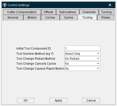
Initial Tool Component ID — Specifies the Tool Index Number of the tool component initially active for tool changes.
Tool Number Method — Controls how to interpret tool number word/addresses (e.g. Tn). Options are:
-
Select Only — Tool number only selects the tool. The tool is changed by a separate command, e.g. M6)
-
Select & Change — Tool number selects and changes the tool. A separate tool change command is not used.
Tool Change Retract Method — Method of retracting for a tool change. Methods which retract machine axes reference location values stored in a Tool Change Location table. Options are:
-
No Retract — Change the tool at its current location.
-
Retract (Z-Axis only) — Retract the tool only along the Z-axis.
-
Retract All Axes — Retract all machine motion axes to their respective tool change locations.
-
Retract Tool Side Axes — Similar to Retract All Axes, except applies only to motion axes connected between the machine Base and Tool components.
-
Use Retraction Table — Refer to the Tool Change Retraction table (ref. Tool Change Retraction table in the Offsets section of the Vericut Help) to determine which machine axes to retract.
Tool Change Cancels Cycles — When active (Yes), cancels canned cycles with a tool change.
Tool Change Causes Rapid Motion — When active (Yes), sets the rapid motion mode with a tool change.
See Configuring "Tooling" NC Control Settings in the Using the Control Settings window section of Vericut Help for additional information.
Control Settings window, Rotary tab
Location:
Machine/Control tab >  (Control Settings)
Toolbar short cut: ![]()
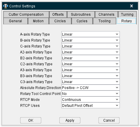
The features on the Rotary tab enable you to configure how rotary motion commands are interpreted, e.g. A, B, C. A "moving tool philosophy" is assumed when describing rotations.
📝 NOTE: In the following descriptions, clockwise (CW) and counter-clockwise (CCW) are always determined by looking down the rotary axis.
A-axis Rotary Type, B-axis Rotary Type, C-axis Rotary Type — The following settings control how rotary commands are interpreted (e.g. ABC). Each axis is individually controlled. Options are:
-
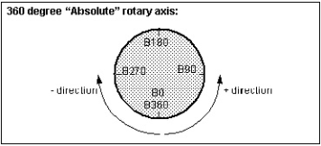
EIA (360 Absolute) — Refers to absolute angle positions. Absolute Rotary Direction controls how rotation values determine the direction of rotation.
-
Linear — Refers to angles on a linear axis "wrapped" around the rotary component. In absolute input dimension mode (e.g. G90), rotary values specify absolute locations along the linear-rotary axis, while the sign (+ / -) controls which end of the linear axis is used. In incremental input dimension mode (e.g. G91), rotary values specify degrees to rotate from the current position, and the sign controls the direction of rotation: plus = CCW, minus = CW.
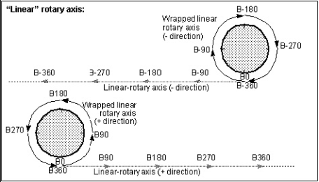
Example rotations of a B-axis linear-rotary component:
| Current axis position | Command | Rotary motion (moving tool philosophy) | Rotary destination |
|---|---|---|---|
| B0 | G90B75 | 75 deg CCW | B75 |
| B0 | G90B-75 | 75 deg CW | B285 (B-75) |
| B35 | G90B75 | 40 deg CCW | B75 |
| B35 | G90B-75 | 110 deg CW | B285 (B-75) |
| B150 | G90B120 | 30 deg CW | B120 |
| B150 | G90B-120 | 270 deg CW | B240 (B-120) |
| N/A | G91B75 | 75 deg CCW | Current +75 |
| N/A | G91B-75 | 75 deg CW | Current -75 |
A2-axis Rotary Type, B2-axis Rotary Type, C2-axis Rotary Type — The settings control how rotary commands for secondary rotary axes are interpreted (e.g. A2, B2, C2). Each axis is individually controlled. Options are same as described above for ABC rotary types.
Absolute Rotary Direction — Controls how rotation values determine the direction of rotation for EIA (360 Absolute) rotary type components. Options and examples follow.
- Positive -> CCW — Sign controls the direction of rotation: plus = CCW, minus = CW and the absolute value of the rotation value specifies the rotary destination.
📝 NOTE: You can configure the same behavior using Configuration menu > Word/Address and associating the RotaryDirPosCCW macro.
| Current axis position | Command | Rotary motion (moving tool philosophy) | Rotary destination |
|---|---|---|---|
| NA | G90B0 | NA | B0 |
| B0 | G90B380 | 20 deg CCW | B20 |
| B20 | G90B-90 | 290 deg CW | B90 |
| B90 | G90B60 | 330 deg CCW | B60 |
- Positive -> CW — Similar to Positive -> CCW, except the rotation directions are reversed.
📝 NOTE: You can configure the same behavior using Configuration menu > Word/Address and associating the RotaryDirPosCW macro.
Examples of rotary behavior with Absolute Rotary Direction=Positive -> CW:
| Current axis position | Command | Rotary motion (moving tool philosophy) | Rotary destination |
|---|---|---|---|
| NA | G90B0 | NA | B0 |
| B0 | G90B380 | 340 deg CW | B20 |
| B20 | G90B-90 | 70 deg CCW | B90 |
| B90 | G90B60 | 30 deg CW | B60 |
- Always CCW — Rounds the rotation value to increments of 360, then subtracts 360 until the subtracted value is between 0-360. The rounded value specifies the rotary destination. The tool always rotates in a counter-clockwise direction about the rotary center point.
📝 NOTE: You can configure the same behavior using Configuration menu > Word/Address and associating the RotaryDirCCW macro.
Examples of rotary behavior with Absolute Rotary Direction=Always CCW:
| Current axis position | Command | Rotary motion (moving tool philosophy) | Rotary destination |
|---|---|---|---|
| NA | G90B0 | NA | B0 |
| B0 | G90B380 | 20 deg CCW | B20 |
| B20 | G90B-90 | 250 deg CCW | B270 |
| B270 | G90B60 | 150 deg CCW | B60 |
- Always CW — Rounds the rotation value to increments of 360, then subtracts 360 until the subtracted value is between 0-360. The rounded value specifies the rotary destination. The tool always rotates in a clockwise direction about the rotary center point.
📝 NOTE: You can configure the same behavior using Configuration menu > Word/Address and associating the RotaryDirCW macro.
Examples of rotary behavior with Absolute Rotary Direction=Always CW:
| Current axis position | Command | Rotary motion (moving tool philosophy) | Rotary destination |
|---|---|---|---|
| NA | G90B0 | NA | B0 |
| B0 | G90B380 | 340 deg CW | B20 |
| B20 | G90B-90 | 110 deg CW | B270 |
| B270 | G90B60 | 210 deg CW | B60 |
A3-axis Rotary Type, B3-axis Rotary Type, C3-axis Rotary Type — The settings control how rotary commands for secondary rotary axes are interpreted (e.g. A2, B2, C2). Each axis is individually controlled. Options are same as described above for ABC rotary types.
Absolute Rotary Direction — Controls how rotation values determine the direction of rotation for EIA (360 Absolute) rotary type components. Options and examples follow.
- Positive -> CCW — Sign controls the direction of rotation: plus = CCW, minus = CW and the absolute value of the rotation value specifies the rotary destination.
📝 NOTE: You can configure the same behavior using Configuration menu > Word/Address and associating the RotaryDirPosCCW macro.
| Current axis position | Command | Rotary motion (moving tool philosophy) | Rotary destination |
|---|---|---|---|
| NA | G90B0 | NA | B0 |
| B0 | G90B380 | 20 deg CCW | B20 |
| B20 | G90B-90 | 290 deg CW | B90 |
| B90 | G90B60 | 330 deg CCW | B60 |
- Positive -> CW — Similar to Positive -> CCW, except the rotation directions are reversed.
📝 NOTE: You can configure the same behavior using Configuration menu > Word/Address and associating the RotaryDirPosCW macro.
Examples of rotary behavior with Absolute Rotary Direction=Positive -> CW:
| Current axis position | Command | Rotary motion (moving tool philosophy) | Rotary destination |
|---|---|---|---|
| NA | G90B0 | NA | B0 |
| B0 | G90B380 | 340 deg CW | B20 |
| B20 | G90B-90 | 70 deg CCW | B90 |
| B90 | G90B60 | 30 deg CW | B60 |
- Always CCW — Rounds the rotation value to increments of 360, then subtracts 360 until the subtracted value is between 0-360. The rounded value specifies the rotary destination. The tool always rotates in a counter-clockwise direction about the rotary center point.
📝 NOTE: You can configure the same behavior using Configuration menu > Word/Address and associating the RotaryDirCCW macro.
Examples of rotary behavior with Absolute Rotary Direction=Always CCW:
| Current axis position | Command | Rotary motion (moving tool philosophy) | Rotary destination |
|---|---|---|---|
| NA | G90B0 | NA | B0 |
| B0 | G90B380 | 20 deg CCW | B20 |
| B20 | G90B-90 | 250 deg CCW | B270 |
| B270 | G90B60 | 150 deg CCW | B60 |
- Always CW — Rounds the rotation value to increments of 360, then subtracts 360 until the subtracted value is between 0-360. The rounded value specifies the rotary destination. The tool always rotates in a clockwise direction about the rotary center point.
📝 NOTE: You can configure the same behavior using Configuration menu > Word/Address and associating the RotaryDirCW macro.
Examples of rotary behavior with Absolute Rotary Direction=Always CW:
| Current axis position | Command | Rotary motion (moving tool philosophy) | Rotary destination |
|---|---|---|---|
| NA | G90B0 | NA | B0 |
| B0 | G90B380 | 340 deg CW | B20 |
| B20 | G90B-90 | 110 deg CW | B270 |
| B270 | G90B60 | 210 deg CW | B60 |
- Shortest Distance — Vericut uses the rotation value and its sign to determine the absolute rotary position. The rotary moves in the direction that is shortest. If the move is exactly 180 degrees, both directions are equally short. The direction of is move is undefined. Vericut will therefore pick a direction, and output the following Warning message: “Warning: The direction to move is undefined (180 degree move set to Shortest Distance)”.
If you do not want the warning message, you must pick one of the other “Shortest Distance” types which defines the direction to take in the case of a 180 degree move.
📝 NOTE: You can configure the same behavior using Configuration menu > Word/Address and associating the RotaryDirShortestDist macro.
Examples of rotary behavior with Absolute Rotary Direction=Shortest Distance:
| Current axis position | Command | Rotary motion (moving tool philosophy) | Rotary destination |
|---|---|---|---|
| NA | G90B0 | NA | B0 |
| B0 | G90B380 | 20 deg CCW | B20 |
| B20 | G90B-90 | 110 deg CW | B270 |
| B270 | G90B60 | 150 deg CCW | B60 |
- Linear — Rounds the rotation value to increments of 360, then subtracts 360 until the subtracted value is between 0-360. The difference between the rounded value and the current position is the rotary destination while the sign of the difference specifies the rotation direction. A positive difference value rotates the tool in a CCW direction about the rotary center point, a negative value rotates the tool in a CW direction.
📝 NOTE: You can configure the same behavior using Configuration menu > Word/Address and associating the RotaryDirLinear macro.
Examples of rotary behavior with Absolute Rotary Direction=Linear:
| Current axis position | Command | Rotary motion (moving tool philosophy) | Rotary destination |
|---|---|---|---|
| NA | G90B0 | NA | B0 |
| B0 | G90B380 | 20 deg CCW | B20 |
| B20 | G90B-90 | 250 deg CCW | B270 |
| B270 | G90B60 | 210 deg CW | B60 |
-
Shortest Distance - 180 CW — Uses the rotation value and its sign to specify the absolute rotary position. The rotary moves in the direction that is shortest. If the move is exactly 180 degrees, it will always move in a clockwise direction.
📝 NOTE: You can configure the same behavior using Configuration menu > Word/Address and associating the RotaryDirShortestDist180CW macro. -
Shortest Distance - 180 CCW — Uses the rotation value and its sign to specify the absolute rotary position. The rotary moves in the direction that is shortest. If the move is exactly 180 degrees, it will always move in a counter-clockwise direction.
📝 NOTE: You can configure the same behavior using Configuration menu > Word/Address and associating the RotaryDirShortestDist180CCW macro. -
Positive -> CW ABSOLUTE — Similar to Positive -> CCW ABSOLUTE, but rotary directions are reversed. This feature sets the direction for an EIA (360 Absolute) rotary table to be clockwise when the angle is positive and counterclockwise when the angle is negative.
📝 NOTE: You can configure the same behavior using Configuration menu > Word/Address and associating the RotaryDirPosCWAbsolute macro. -
Positive -> CCW ABSOLUTE — Sets the direction for an EIA (360 Absolute) rotary table to be counter-clockwise when the angle is positive and clockwise when the angle is negative.
📝 NOTE: You can configure the same behavior using Configuration menu > Word/Address and associating the RotaryDirPosCCWAbsolute macro. -
Shortest Distance 2 — The rotary moves in the direction that is shortest. If the move is exactly 180 degrees, the starting and ending angles will be converted into an angle between 0-360 degrees. Then if you are moving to a larger angle, the rotary will move clockwise. If you are moving to a smaller angle, the rotary will move counter-clockwise. The only exception is when moving from 180 degrees to 0 degrees, the rotary will move in a clockwise direction. For example:
0 to 180 → CW
30 to 210 → CW
210 to 30 → CCW
180 to 0 → CW
-90 to 90 (270 to 90) → CCW
📝 NOTE: You can configure the same behavior using Machine/Control menu > Word/Address and associating the RotaryDirShortestDist2 macro.
- Shortest Distance 3 — The rotary moves in the direction that is shortest. If the move is exactly 180 degrees, the starting and ending angles will be converted into an angle between 0-360 degrees. Then if you are moving to a larger angle, the rotary will move clockwise. If you are moving to a smaller angle, the rotary will move counter-clockwise. For example:
0 to 180 → CW
30 to 210 → CW
210 to 30 → CCW
180 to 0 → CCW
-90 to 90 (270 to 90) → CCW
📝 NOTE: You can configure the same behavior using Machine/Control menu > Word/Address and associating the RotaryDirShortestDist3 macro.
See G-Code Processing window section of Vericut Help for additional information.
See Vericut Macros in the Vericut Help Library for information about the macros named in the above Notes, and all Vericut macros.
- Shortest Distance - 180 LINEAR — The rotary moves in the direction that is shortest. If the move is exactly 180 degrees, the starting and ending angles will be converted into an angle between 0-360 degrees. Then if you are moving to a larger angle, the rotary will move clockwise. If you are moving to a smaller angle, the rotary will move counter-clockwise. For example:
0 to 180  CW
CW
30 to 210 CW
210 to 30 CCW
180 to 0 CW
-90 to 90 (270 to 90) CCW
📝 NOTE: You can configure the same behavior using Machine/Control menu > Word/Address and associating the RotaryDirShortestLinear macro.
- Shortest Distance 4 — The rotary moves in the direction that is shortest. If the move is exactly 180 degrees, then the starting and ending angles are converted into an angle between 0-360. If you are moving to a larger angle, the rotary will move clockwise. If you are moving to a smaller angle, the rotary will move counter-clockwise. The two exceptions are when moving from 180 degrees to 0 degrees, the rotary will move in a clockwise direction, and when moving from 0 to 180 degrees, the rotary will move in a counter clockwise direction. For example:
0 to 180 → CCW
30 to 210 → CW
210 to 30 → CCW
180 to 0 → CW
-90 to 90 (270 to 90) → CCW
See G-Code Processing window section of Vericut Help for additional information.
See Vericut Macros in the Vericut Help Library for information about the macros named in the above Notes, and all Vericut macros.
- Shortest Distance 5 — The rotary moves in the direction that is shortest. If the move is exactly 180 degrees, then convert the starting and ending angles into a value within the interval I = [-180,179.99999]. If the angle the rotary is moving to is larger than its starting angle position, then the Rotary will move clockwise. If the angle the rotary is moving to is smaller than its starting angle position, then the Rotary will move counter clockwise. For example:
0 to 180 (0 to -180) → CCW
30 to 210 (30 to -150) → CCW
210 to 30 (-150 to 30) → CW
180 to 0 (-180 to 0) → CW
-90 to 90 (-90 to 90) → CW
See G-Code Processing window section of Vericut Help for additional information.
See Vericut Macros in the Vericut Help Library for information about the macros named in the above Notes, and all Vericut macros.
- Shortest Distance 6 — The rotary moves in the direction that is shortest. If the move is exactly 180 degrees, then convert the starting and ending angles into a value within the interval I = [-179.99999,180]. If the angle the rotary is moving to is larger than its starting angle position, then the Rotary will move clockwise. If the angle the rotary is moving to is smaller than its starting angle position, then the Rotary will move counter clockwise. For example:
0 to 180 (0 to 180) → CW
30 to 210 (0 to -150) → CCW
210 to 30 (-150 to 30) → CW
180 to 0 (180 to 0) → CCW
-90 to 90 (-90 to 90) → CW
See G-Code Processing window section of Vericut Help for additional information.
See Vericut Macros in the Vericut Help Library for information about the macros named in the above Notes, and all Vericut macros.
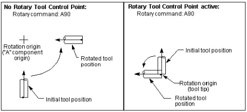
Rotary Tool Control Point — When active (Yes), with default settings, Rotary Tool Control Point, or "RTCP" causes rotary motion about a specific control point-typically the tool tip. When RTCP is not active (No), rotation occurs about the rotary component origins. This feature is intended for use only with tilting head machines.
RTCP compensates for the gage offset (XYZ distance from tool tip to Tool component) and pivot offset (XYZ distance from spindle face/centerline to tool side rotary components rotation/pivot point) as tool side rotary components rotate.
Effect of using RTCP with an A-axis rotary component:
RTCP only applies to rotary components between a Tool component and the Base component (tool side). Rotary components between a Stock component and the Base component (part side) do not affect the orientation of the tool, and therefore do not affect the tool side offsets.
RPCP, or Rotary Part Control Point, is used with part side rotary components, where the part is moved relative to the tool tip. RPCP actually rotates the workpiece coordinate system as the part side rotary components rotate. RPCP should only be used when programming in the part coordinate system. See the "RpcpOn, RpcpOff" macros, in the Vericut Macros section, or the "RPCP Pivot Offset table" in the Tables for Processing G-Codes section, for more information. Both can be found in the Vericut Help Library.
📝 NOTES:
-
The default state for RTCP is set on the Rotary Settings panel. The RTCP state can be modified via the RotaryControlPointOnOff or RtcpOn, RtcpOff macros.
-
See also: "RTCP Pivot Offset table" or "RPCP Pivot Offset table" for possible additional configuration for correct RTCP simulation.
RTCP Mode — This feature is only active if RTCP is turned on. This field is used to specify the default mode setting, which can then be overridden by using the RtcpMode macro. Choose one of the following:
-
Continuous — The machines axes will be continually updated as the tool rotates in order to keep the tool tip on path. This means that if only an A rotation is programmed (assume A is a rotary on the Tool Side), then all axes will move in order to keep the tool tip motionless as the tool rotates.
-
At End Point — The final end point is calculated, and the machine is sent directly to this location. The end result is: if only an A rotation is programmed (assume A is a rotary on the Tool Side), then the tool tip will move as the tool rotates, but it will end up in its original location.
-
Only as XYZ is Specified — If XYZ is specified on the block with the rotary move, than this mode is the same as “At End Point”. If XYZ is not specified on the block with the rotary move, than only the rotary will move. As each axis is specified, the corresponding offset will then be applied.
RTCP Uses — Use this feature to specify which type of pivot offset compensation to use. The options are:
-
Default Pivot Offset: This option is not recommended and may be removed in the future.
-
Gage Pivot Offset: The Gage Pivot offset is the offset from the current position of the active Tool to the Pivot point. The Pivot point by default is the highest rotary above the Tool. This option makes use of the macros PivotOffsetCompName and PivotOffsetCompNameB to adjust the FROM and TO points. In this scenario, the Work Offset is typically measured from the Pivot Point.
-
RTCP Pivot Offset: This option is not recommended, and may be removed in the future
-
Only Gage Offset: The Gage Pivot offset is always set to Zero
-
Gage Spindle Offset: The Gage Pivot Offset is the offset from the current position of the Spindle to where the Spindle would be if the Tool side rotaries were at zero. In this scenario, the Work Offset is typically measured from the Spindle.
Choose one of the following:
-
Default Pivot Offset — Use the RTCP Pivot Offset compensation type. The ApplyGagePivotOffset macro can be used to switch to the Gage Pivot Offset compensation type.
-
Gage Pivot Offset — Use the Gage Pivot Offset compensation type. This option should be used for all new jobs.
📝 NOTE: The Gage Pivot Offset might currently be turned off, or may be set to (0,0,0). -
RTCP Pivot Offset — Use the RTCP Pivot Offset compensation type.
📝 NOTE: The RTCP Pivot Offset might currently be turned off, or may be set to (0,0,0). -
Only Gage Offset — Do not compensate for XYZ pivot offset. Compensate only for the XYZ gage offset.
📝 Tech Notes:
Traditionally, Rotary Tool Control Point (RTCP) referred to a state in which the tool would rotate about the tool tip when a tool-side rotary was rotated.
Today this feature has a more generic definition. Rotary Tool Control Point refers to a state in which the tool side offsets are automatically updated when a tool-side rotary is rotated. This means that even though Rotary Tool Control Point is active, the results might not be as described above for the following reasons:
-
The traditional definition assumed that the offsets are adjusted continually as the rotary axis is rotated. This is not always the case. In the above diagram, an "A90" command is being executed. If the offsets are not updated continuously, the tool tip position will not stay fixed, but will "wander", and then end up in its original position. The RTCP Contour flag allows for configuration of either type.
-
The traditional definition assumed that the offsets would be applied immediately to all axes even though the corresponding linear axes were not specified on the block. This is not always the case. If the offsets are only applied when the corresponding linear axes are specified, then in the above case (A90), even though RTCP was active, the machine would behave as illustrated on the left. Then when XYZ is specified (with the original coordinates), then the updated offsets would be applied, and the tool tip would return to its original position. The RTCP With Motion flag allows for configuration of either type.
Some controls only adjust some of the 4 tool side offsets. If this is true, then the tool tip will not return to the original position.
See Configuring "Rotary" NC Control Settings, in the Using the Control Settings window section of Vericut Help for additional information.
Control Settings window, Cutter Compensation tab
Location:
Machine/Control tab >  (Control Settings)
Toolbar short cut: ![]()
The features on the Cutter Compensation tab enables you to configure how the programmed tool path is compensated when cutter diameter compensation, or "CDC" is used, e.g. G41-42. Enter CDC offset values into a Cutter Compensation table. To apply CDC offsets to the programmed tool path, ensure Process Cutter Comp. is active.
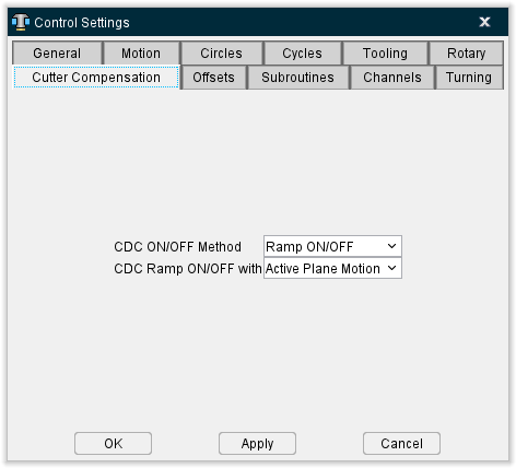
CDC ON/OFF Method — Controls how the offset condition is established when CDC is turned on, and how the offset is cancelled when CDC is turned off. Options:
-
Ramp ON/OFF — Establish the offset condition with a "ramp-on" motion after CDC is turned on. When CDC is turned off, the offset is cancelled with a "ramp-off" motion on the next tool move.
-
Immediate — Immediately establishes the offset condition when CDC is turned on, and assumes the offset has been established by a prior data block (e.g. G43-44 as interpreted by the Phillips CNC controls). When CDC is turned off, the offset is cancelled without a tool move.
CDC Ramp ON/OFF with — Specifies the motion types which establish/cancel the CDC offset. Options:
-
Active Plane Motion — Use to turn CDC on with a motion in the active cutting plane.
-
Any Motion — Use to turn CDC on with any motion, including motion along the tool axis.
See Configuring "Cutter Compensation" NC Control Settings, in the Using the Control Settings window section of Vericut Help for additional information.
Control Settings window, Offsets tab
Location:
Machine/Control tab >  (Control Settings)
Toolbar short cut: ![]()
The features on the Offsets tab enable you to configure an initial work offset, or "fixture offset", to be in effect at the start of NC program processing.
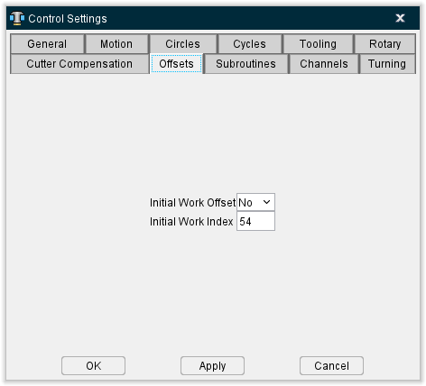
Initial Work Offset — When active (Yes), sets the initial work offset specified by the Initial Work Index (see below).
Initial Work Index — The index or offset register value containing the initial work offset or shift offset. The offset remains effective until a different work offset (e.g. G54-59) is processed, or until cancelled. Enter the corresponding offset values into a Work Offsets table or Shift Offsets table (ref. Work Offsets/Shift Offsets table, in the Offsets section of the Vericut Help).
See Configuring "Offsets" NC Control Settings, in the Using the Control Settings window section of Vericut Help for additional information.
Control Settings window, Subroutines tab
Location:
Machine/Control tab >  (Control Settings)
Toolbar short cut: ![]()
The features on the Subroutines tab enable you to configure how subroutine names are referenced by the NC control.
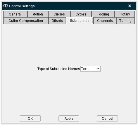
Type of Subroutine Names — Controls how names of subroutines are referenced. Options are:
-
Numeric — Use the numeric value; leading zeros are ignored. For example, "O0010" is interpreted the same as "O10".
-
Text — Use the text string value. For example, "O0010" is not interpreted the same as the name "O10".
See Configuring "Subroutines" NC Control Settings, in the Using the Control Settings window section of Vericut Help for additional information.
Also see About Simulating Subroutines, in the Building NC Controls section of Vericut Help for general information about simulating subroutines.
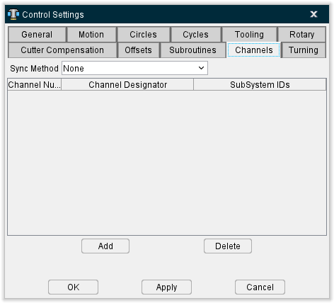
Control Settings window, Channels tab
Location:
Machine/Control tab >  (Control Settings)
Toolbar short cut: ![]()
The features on the Channels tab enable you to set up Vericut for simulating machining with synchronized subsystems.
The term "sync" refers to the idea of synchronizing multiple programs (or channels) at once. A program could be defined by a separate input file, or by sections of a single input file. Each of these programs drives a subsystem. The sync logic will obtain motions for all subsystems being synced, and then execute the motion. For example: If the upper system has a motion that will take 3 seconds, and the lower subsystem has a motion that will take .5 seconds. The lower subsystem motion and ⅙th of the upper subsystem motion will be executed. Then, the next motion will then be retrieved for the lower subsystem, and the process continues. The Info tab > NC Program panel shows which blocks are being processed by the programs.
📝 NOTE: The actual synchronization of the programs based on WAIT or SYNC codes are controlled by the G-Code Processing table.
Sync Method — The Sync Method turns on/off the Sync logic, and specifies the method that will be used to determine which data applies to which subsystem. Options include:
-
None — (Default) Turns off Sync logic. Normal processing occurs.
-
G&L - N/O Block — An "N" sequence numbers mark commands for the first subsystem, "O" sequence numbers marks commands for the second subsystem, and "B" sequence numbers marks commands for both subsystems.
-
Okuma - G13/G14 — The input program is divided into sections. Each section begins with either a G13 or a G14. The G13 sections will drive the first subsystem, and the G14 sections will drive the second subsystem.
-
Fanuc - Multiple NC Programs — Independent NC program files are specified for each synced subsystem. The order of the subsystems specified must match the order of the NC program files in the NC Program list.
-
INDEX - Channel 1/Channel 2 — A single NC program file contains two subroutines, one for each head. A word/value, for example "M30", toggles between "channels" that control each head. These channels will then drive the corresponding subsystems. See the IndexCallMainSub macro in the Vericut Macros section of the Vericut Help Library for more information.
-
Gildemeister - \(1/\)2 — Blocks starting with $1 will be processed by the first subsystem, and blocks starting with $2 will be processed by the second subsystem. Blocks not beginning with either a $1 or a $2 will be processed by both subsystems.
-
Mazak - G109L1/G109L2 — The input program is divided into sections. Each section begins with either a G109L1 or a G109L2. The G109L1 sections will drive the first subsystem, and the G109L2 sections will drive the second subsystem.
-
Allen-Bradley - Primary/Secondary — This sync type has the following attributes:
-
A block can contain commands for both subsystems (controls).
-
Each control is processed independently.
- The next block is not processed until both controls are done with the previous block.
- Although the split up of the Info NC Program panel is not necessary (or possibly desirable) for this sync type, it is still done for consistency with the way we handle sync motion.
- When "stepping", both the upper and lower NC Program panels (controls) will process 1 block.
-
The MDI window will ignore the subsystem specified, and will process the line as stated by sending it to both controls.
-
Citizen - \(1/\)2/$3 — The input program is divided into sections. Each section begins with a $1, a $2, or a $3. The $1 sections will drive the first subsystem, the $2 sections will drive the second subsystem, and the $3 sections will drive the third subsystem.
-
Generic – User Defined — This sync method uses a single NC program file but can have any number of input channels. The Input Channel field is an editable field enabling you to specify the text string used in the NC program file to identify each input channel. The Sync SubSystem IDs field has a pull-down list of defined subsystems. See the sample Control Settings window below.
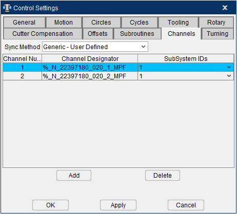
Upon Reset, the NC Program panel you will show both channels using the same NC program. Also notice that initially, Line 1 of both channels display the Input Channel identifier for channel 1. When the simulation gets to the first axis motion, Channel 2 will jump to the Input Channel identifier for channel 2. You also need to adjust the work offsets for each channel.
Pilot 4290 - \(1/\)2/$3 — $1 drives the first subsystem, $2 drives the second subsystem, and #3 drives the third subsystem. Three subsystems are supported with the Pilot 4290 sync type.
The input program is divided into multiple sections. Each section begins with a ZUORDNUNG statement. For example, the statement ZUORDNUNG \(1\)3 specifies that the following program section is to be read by subsystem 1 and subsystem 3.
If a $1, $2, or $3 is present at the beginning of a line, this will override the ZUORDNUMG statement and only the specified subsystem will read this line.
Sin840D - INIT, START, WAITE — This sync method is used for the standard Siemens Sin840D Sync mechanism for handling Sync jobs. The job starts as a single channel job. The key codes are INIT, START, and WAITE
-
INIT: defines the subroutine that the second channel should process
-
START: starts the second channel
-
WAITE: tells the first head to wait here until the second channel reaches the end of file.
When the second channel reaches the EOF, the job returns to a single channel job.
Currently, this sync type only supports 2 channels. With this sync type, the status of the second channel is initialized to EOF.
The macro Siemens840DSyncBegin is used to pass in the program that the second channel should run.
When called from the first channel, it will activate (change the status) of the second channel, and set its starting location to be the current line.
When called from the second channel, it will strip off the “SPF” suffix, the Path name, and the “_N” prefix and then call this subroutine. When the second channel is done with this program, it will mark its status as EOF, thereby deactivating himself.
The macro Siemens840DSyncEnd causes the first channel to wait until the second channel reaches EOF.
See Vericut Macros in the Vericut Help Library for information on these, and all, Vericut macros.
Sync Table
Each record in the Sync Table represent the information related to a particular "sync'd" subsystem.
Index — This field is used to identify the sync record.
Input Channel — This field defines what is driving each channel. The information displayed here will be different depending on the Sync Method being used.
Sync SubSystem IDs — This field defines the SubSystem that will be driven by the specified Input Channel. Select the subsystem ID from the pull-down list.
The number of records in the Sync Table must match the Sync Method defined above. For example the Citizen must have 3 Sync records, and the Okuma must have 2. The Fanuc style could have any number of Sync records.
📝 NOTE: A machine might define a separate subsystem for a head changer, a palette changer, … These are not Sync SubSystems. The Sync SubSystems corresponds to the primary SubSystem that is being driven by each of the Sync'd channels.
Add — Use to add a record to the Sync Table after the highlighted SubSystem ID.
Delete — Use to delete the highlighted record from the Sync Table.
↘️ Shortcut: You can right-click in the Sync Subsystems IDs Table to display the following menu.

These provide the same functionality as Add and Delete described above.
💡 Tip: Once you have set up the sync environment using the features in this tab, you can use the features on the G-Code Advanced Settings window to turn off one or more subsystems to assist in debugging Sync related problems.
See Configuring "Channels" NC Control Settings, in the Using the Control Settings window section of Vericut Help for additional information.
Control Settings window, Turning tab
Location:
Machine/Control tab >  (Control Settings)
Toolbar short cut: ![]()
The features on the Turning tab enable you to configure Vericut for lathe turning simulations.
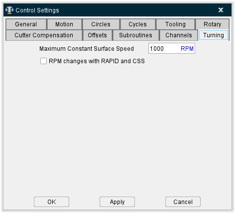
CSS Maximum RPM — When constant surface speed, or "CSS" is controlling spindle speed, this value specifies the fastest RPM to turn the workpiece.
RPM Changes with RAPID and CSS — When toggled on (checked) and CSS is controlling spindle speed, rapid motions (e.g. G0) can affect spindle speed, as well as linear and circular motions (e.g. G1-3). Clear this checkbox to have only linear and circular motions affect RPM.
See Configuring "Turning" NC Control Settings, in the Using the Control Settings window section of Vericut Help for additional information.
Using the Control Settings window
Configuring "General" NC Control Settings
Use the procedure described below to configure general guidelines for how the control processes machine codes and number equations.
To configure general settings in the NC control file:
- Click on
 (Control Settings) in the Toolbar or click on Machine/Control tab > Control Settings in the Vericut menu ribbon to display the Control Settings window.
 -
Click on the General tab.
The features on the General tab enable you to configure general guidelines for how the control processes machine code data and number equations.
See Control Settings window: General tab section of Vericut Help for additional information. -
Set Control Type: choose Generic for Fanuc and most other controls. Other options are: NUM (French-made control), or Heidenhain Conversational, Siemens, Toshiba, Heidenhain ISO, K&T, or Okuma OSP.
- Set the Calculation Tolerance for evaluating mathematical evaluations.
- Choose the Order of Math Operations (normally Rules of Precedence).
- If NC data blocks begin a number instead of a letter (example "50G01X5"), specify a Default Word so Vericut interprets the number as a sequence numbers, for example "N".
- Press Apply to accept the settings and leave the Control Settings window open for additional work or OK to accept the settings and close the Control Settings window.
- Save the Control file by clicking on
 (Save Control) or
  (Save Control As) in the Toolbar or click on Machine/Control tab > Save Control (or Save As) in the Vericut menu ribbon, to save the settings as part of the "current" NC control configuration.
Configuring "Motion" NC Control Settings
Use the procedure described below to configure settings in affect when the control and machine are initially powered on, such as: default NC control motion states, and the precision used when outputting calculated values.
To configure default motion and output precision settings in the control:
- Click on
 (Control Settings) in the Toolbar or click on Machine/Control tab > Control Settings in the Vericut menu ribbon to display the Control Settings window.
 -
Click on the Motion tab.
The features on the Motion tab enable you to configure default NC control motion states, and specify the precision used when outputting calculated values. These settings are in affect when the control and machine are initially powered on.
See Control Settings window: Motion tab section of Vericut Help for additional information. -
Configure the "Default" options applicable to the control: default motion type, plane selection, etc.
-
To start the machine at a location other than machine zero, ensure Output Initial Spindle Location is active (Yes). Then enter the initial spindle location values into an Initial Machine Location table.
For table-specific information, such as data entry formats and how they affect Vericut, refer to the Initial Machine Location table section, in Offsets section of the Vericut Help Library. -
If applicable, set appropriate motion types to cancel canned cycles: rapid, linear, CW, etc.
- Configure Output Rapid Motions as and Maximum Inverse Time Output Feedrate as required to process rapid motions.
- Set the Output Precision for interpreting calculated values, such as: CDC offset positions, mathematical operations, etc.
- If required, enter a value for Specified Output Precision that matches what then NC control uses for these calculations.
- Press Apply to accept the settings and leave the Control Settings window open for additional work or OK to accept the settings and close the Control Settings window.
- Save the Control file by clicking on
 (Save Control) or (Save Control As) in the Toolbar or click on Machine/Control tab > Save Control (or Save As) in the Vericut menu ribbon, to save the settings as part of the "current" NC control configuration.
Configuring "Circles" NC Control Settings
Use the procedure described below to configure settings for interpreting circle center (e.g. IJK) and helical motion data.
To configure circle/helical motion settings in the control:
- Click on
 (Control Settings) in the Toolbar or click on Machine/Control tab > Control Settings in the Vericut menu ribbon to display the Control Settings window.
 -
Click on the Circles tab.
The features on the Circles tab enable you to configure how the circle center data (e.g. IJK) is interpreted. The Interpolation Tolerance determines the quantity of machine positions which simulate arc and helical motions.
See Control Settings window: Circles tab section of Vericut Help for more information. -
Configure the features on the Circles tab as required.
- Press Apply to accept the settings and leave the Control Settings window open for additional work or OK to accept the settings and close the Control Settings window.
- Save the Control file by clicking on
 (Save Control) or (Save Control As) in the Toolbar or click on Machine/Control tab > Save Control (or Save As) in the Vericut menu ribbon to save the settings as part of the "current" NC control configuration.
Configuring "Cycles" NC Control Settings
Use the procedure described below to configure settings for interpreting tool axis, or "canned" cycle motion blocks (e.g. G8n...).
To configure canned cycle settings in the control:
- Click on
 (Control Settings) in the Toolbar, or click on Machine/Control tab > Control Settings in the Vericut menu ribbon, to display the Control Settings window.
 -
Click on the Cycles tab.
The features on the Cycles tab enable you to configure how fixed tool axis, or "canned" cycle motion blocks are interpreted, e.g. G8n.
See Control Settings window: Cycles tab section of Vericut Help for additional information. -
Configure the features on the Cycles tab as required.
- Press Apply to accept the settings and leave the Control Settings window open for additional work or OK to accept the settings and close the Control Settings window.
- Save the Control file by clicking on
 (Save Control) or (Save Control As) in the Toolbar or click on Machine/Control tab > Save Control (or Save As) in the Vericut menu ribbon to save the settings as part of the "current" NC control configuration.
Configuring "Tooling" NC Control Settings
Use the procedure described below to configure settings for default tooling conditions and tool change activity.
To configure tooling and tool change settings in the control:
- Click on
 (Control Settings) in the Toolbar or click on Machine/Control tab > Control Settings in the Vericut menu ribbon to display the Control Settings window.
 -
Click on the Tooling tab.
The features on the Tooling tab enable you to configure default tooling conditions, and define tool change activity.
See Control Settings window: Tooling tab section of Vericut Help for additional information. -
Configure the features on the Tooling tab as required.
For preselect tooling, choose Tool Number Method = Select Only. -
Press Apply to accept the settings and leave the Control Settings window open for additional work or OK to accept the settings and close the Control Settings window.
-
If Tool Change Retract Method was set to retract any machine axes, enter the corresponding location values into a Tool Change Location table.
If Tool Change Retract Method was set to Use Retraction Table, configure the Tool Change Retraction table with "1s" for axes to retract, and "0s" for axes that do not move during a tool change.
For table-specific information, such as data entry formats and how they affect Vericut, refer to the Tool Change Retraction table section of Offsets in the Vericut Help Library. -
Save the Control file by clicking on
 (Save Control) or (Save Control As) in the Toolbar or click on Machine/Control tab > Save Control (or Save As) in the Vericut menu ribbon, to save the settings as part of the "current" NC control configuration.
Configuring "Rotary" NC Control Settings
Use the procedure described below to configure settings for rotary motion commands (e.g. ABC).
To configure rotary settings in the control:
- Click on
 (Control Settings) in the Toolbar or click on Machine/Control tab > Control Settings in the Vericut menu ribbon to display the Control Settings window.
 -
Click on the Rotary tab.
The features on the Rotary tab enable you to configure how rotary motion commands are interpreted, e.g. A, B, C. A "moving tool philosophy" is assumed when describing rotations.
See Control Settings window: Rotary tab section of Vericut Help for additional information. -
Configure the features on the Rotary tab as required.
- Press Apply to accept the settings and leave the Control Settings window open for additional work or OK to accept the settings and close the Control Settings window.
- Save the Control file by clicking on
 (Save Control) in the Toolbar or click on Machine/Control tab > Save Control (or Save As) in the Vericut menu ribbon to save the settings as part of the NC control configuration.
Configuring "Wire EDM" Control Settings
Use the procedure described below to configure settings for wire EDM machining.
To configure wire EDM settings in the control:
- Click on
 (Control Settings) in the Toolbar or click on Machine/Control tab > Control Settings in the Vericut menu ribbon to display the Control Settings window.
 -
Click on the Wire EDM tab.
The features on the Wire EDM tab enable you to configure wire EDM machining settings.
See Control Settings window: Wire EDM tab also in the Machine/Control tab section of Vericut Help for additional information. -
Configure the features on the Wire EDM tab as required.
- Press Apply to accept the settings and leave the Control Settings window open for additional work or OK to accept the settings and close the Control Settings window.
- Save the Control file by clicking on
 (Save Control) or (Save Control As) in the Toolbar or click on Machine/Control tab > Save Control (or Save As) in the Vericut menu ribbon to save the settings as part of the "current" NC control configuration.
Configuring "Cutter Compensation" NC Control Settings
Use the procedure described below to configure how the programmed tool path is compensated when cutter diameter compensation, or "CDC" is used (e.g. G41-42). When CDC is active, the programmed NC program is simulated just as it will be compensated by the NC control.
To configure the control to simulate cutter compensation:
- Click on
 (Control Settings) in the Toolbar or click on Machine/Control tab > Control Settings in the Vericut menu ribbon to display the Control Settings window.
 -
Click on the Cutter Compensation tab.
The features on the Cutter Compensation tab enables you to configure how the programmed tool path is compensated when cutter diameter compensation, or "CDC" is used, e.g. G41-42. Enter CDC offset values into a Cutter Compensation table. To apply CDC offsets to the programmed tool path, ensure Process Cutter Comp. is active.
See Control Settings window: Cutter Compensation tab section of Vericut Help for additional information.) -
Configure the features on the Cutter Compensation tab as required.
- Press Apply to accept the settings and leave the Control Settings window open for additional work or OK to accept the settings and close the Control Settings window..
-
Enter corresponding offset values into a Cutter Compensation table.
For table-specific information, such as data entry formats and how they affect Vericut, refer to the Cutter Compensation table section, in Offsets in the Vericut Help Library. -
To activate CDC for simulation: ensure that the Process Cutter Comp. feature on the Project Tree, Configure Setup menu: G-Code tab is turned "On".
See Configure Setup menu: G-Code tab in the Project Tree section of Vericut Help for additional information. -
Save the Control file by clicking on
 (Save Control) or (Save Control As) in the Toolbar or click on Machine/Control tab > Save Control (or Save As) in the Vericut menu ribbon to save the settings as part of the "current" NC control configuration.
Configuring "Offsets" NC Control Settings
Use the procedure described below to configure an initial work offset, or "fixture offset", to be in effect at the start of tool path processing.
To configure an initial work offset or shift offset:
- Click on
 (Control Settings) in the Toolbar or click on Machine/Control tab > Control Settings in the Vericut menu ribbon to display the Control Settings window.
 -
Click on the Offsets tab.
The features on the Offsets tab enable you to configure an initial work offset, or "fixture offset", to be in effect at the start of NC program processing.
See Control Settings window: Offsets tab section of Vericut Help. -
Ensure that the Initial Work Offset feature is set to "Yes", and then enter the Initial Work Index (e.g. 54-59) containing the initial offset to apply.
- Press Apply to accept the settings and leave the Control Settings window open for additional work or OK to accept the settings and close the Control Settings window.
-
Enter corresponding offset values into a Work Offsets of Shift Offsets table.
For table-specific information, such as data entry formats and how they affect Vericut, refer to the Work Offsets/Shift Offsets table section, in Offsets in the Vericut Help Library. -
Save the Control file by clicking on
 (Save Control) or (Save Control As) in the Toolbar or click on Machine/Control tab > Save Control (or Save As) in the Vericut menu ribbon to save the settings as part of the "current" NC control configuration.
Configuring "Subroutines" NC Control Settings
Use the procedure described below to configure how subroutine names are referenced by the control.
To configure how subroutine names are referenced by the control:
- Click on
 (Control Settings) in the Toolbar or click on Machine/Control tab > Control Settings in the Vericut menu ribbon to display the Control Settings window.
 -
Click on the Subroutines tab.
The features on the Subroutines tab enable you to configure how subroutine names are referenced by the NC control.
See Control Settings window: Subroutines tab section of Vericut Help for additional information.
Also see About Simulating Subroutines section of Vericut Help for more general information. -
Choose the Type of Subroutine Names which corresponds to how the control references subroutine names:
Numeric — use numeric value (example: "O0010" is interpreted the same as "O10")
Text — use text string value (example: "O0010" is not the same as the name "O10"). -
Press Apply to accept the settings and leave the Control Settings window open for additional work or OK to accept the settings and close the Control Settings window.
💡 Tip: K&T Gemini controls — try the Text type of subroutine names for this control. -
Save the Control file by clicking on
 (Save Control) or (Save Control As) in the Toolbar or click on Machine/Control tab > Save Control (or Save As) in the Vericut menu ribbon to save the settings as part of the "current" NC control configuration.
Configuring "G-code Output Options" NC Control Settings
Use the procedure described below to configure settings for controlling block sequencing and word/value spacing in the optimized NC program file that is output.
To re-sequence or add spaces to optimized G-Code NC program records:
- Click on
 (Control Settings) in the Toolbar or click on Machine/Control tab > Control Settings in the Vericut menu ribbon to display the Control Settings window.
 -
Click on the G-code Output Options tab.
The features on the G-code Output Options tab enable you to configure settings referenced when G-Code NC program files are optimized by Optimization.
The settings are used to control block sequencing and word/value spacing in the optimized output tool path file. Note that by default, optimized blocks receive the same sequence number, if any, that appears on the original block processed. This typically results in multiple blocks having the same sequence number.
See Control Settings window: G-code Output Options tab, also in the Machine/Control tab section of Vericut Help for additional information. -
To re-sequence optimized NC program records:
Set the Auto Sequence Numbering feature to "Yes".
Set the Add Sequence Number to Added Blocks feature to "Yes" if to want sequence numbers added to any additional blocks added by Optimization.
Enter the Sequence Increment Value which defines the starting sequence number and the increment to be used for subsequent sequence numbers. -
To add a space between word/address pairs, set the Word Value Spacing feature to "Yes".
- Press Apply to accept the settings and leave the Control Settings window open for additional work or OK to accept the settings and close the Control Settings window.
- Save the Control file by clicking on
 (Save Control) or (Save Control As) in the Toolbar or click on Machine/Control tab > Save Control (or Save As) in the Vericut menu ribbon, to save the settings as part of the "current" NC control configuration.
Configuring "Channels" NC Control Settings
Use the procedure described below to set up Vericut for simulating machining with synchronized subsystems.
To configure "Channels" settings in the control:
- Click on
 (Control Settings) in the Toolbar or click on Machine/Control tab > Control Settings in the Vericut menu ribbon to display the Control Settings window.
 -
Click on the Channels tab.
The features on the Channels tab enable you to set up Vericut for simulating machining with synchronized subsystems.
See Control Settings window: Channels tab section of Vericut Help for additional information. -
Select the Sync Method from the pull-down list to turn on the Sync logic, and specify the method to be used to determine which data applies to which subsystem.
-
Press the Add button to add a record to the Sync Table.
The record added to the Sync Table will contain default values specific to the selected Sync Method. -
Select the Sync Subsystem ID from the pull-down list for the associated Input Channel as required by your particular machine configuration.
- Repeat steps 4 and 5 until the number of records in the Sync Table match the number required by the Sync Method selected in step 3.
- Press Apply to accept the settings and leave the Control Settings window open for additional work or OK to accept the settings and close the Control Settings window.
- Save the Control file by clicking on
 (Save Control) or (Save Control As) in the Toolbar or click on Machine/Control tab > Save Control (or Save As) in the Vericut menu ribbon to save the settings as part of the "current" NC control configuration.
Configuring "Turning" NC Control Settings
Use the procedure described below to configure settings for turning operations.
To configure turning settings in the control:
- Click on
 (Control Settings) in the Toolbar or click on Machine/Control tab > Control Settings in the Vericut menu ribbon to display the Control Settings window.
 -
Click on the Turning tab.
The features on the Turning tab enable you to configure Vericut for lathe turning simulations.
See Control Settings window: Turning tab section of Vericut Help for additional information. -
Configure the features on the Turning tab as required.
- Press Apply to accept the settings and leave the Control Settings window open for additional work or OK to accept the settings and close the Control Settings window.
- Save the Control file by clicking on
 (Save Control) or (Save Control As) in the Toolbar or click on Machine/Control tab > Save Control (or Save As) in the Vericut menu ribbon to save the settings as part of the "current" NC control configuration.