Colors (Color window)
Location:
Configuration tab >  (Colors)
Toolbar short cut: ![]()
The Colors command button opens the Color window enabling you to define the colors seen in Vericut. Colors are changeable at any time. The effect of changing colors is immediate.
Assign tab — Features on this tab are used to assign Error, Reset Cut and Background colors.
Cut Colors tab — Features on this tab assign colors to machine cuts made in the workpiece.
Define tab — Features on this tab define colors seen in Vericut, and control light brightness.
OK — Saves tab settings and closes the Vericut Color window.
Apply — Saves tab settings and leaves the Vericut Color window open.
Cancel — Closes the Vericut Color window without saving tab settings.
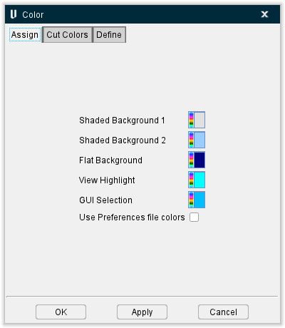
Color window, Assign tab
The features on the Assign tab are used to assign Error, Reset Cut and Background colors.
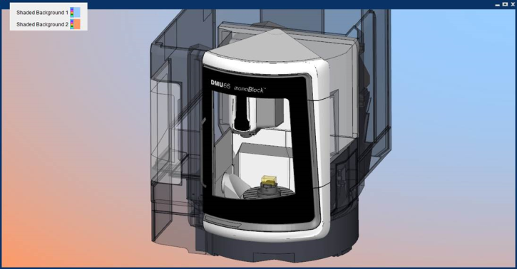
Shaded Background 1 and 2 — Use to specify the color that will be displayed when the view Background attribute is set to Shaded. The colors will gradually transition between the specified colors with Shaded Background 1 starting at the top right and Shaded Background 2 starting at the bottom left of the View window.
Flat Background — Use to specify the color that will be displayed when the Background attribute is set to Flat.
View Highlight — Use to specify the color that will be displayed when a Highlight is viewed by clicking on any material or machine in the View window.
GUI Selection — Use to specify the color that will be displayed when a selection is made in the View window.
Use Preferences file colors — Toggle this feature on (checked) to use the default preferences as your assigned colors.
Color window, Cut Colors tab
The features on the Cut Colors tab enable you to assign colors to the machine cuts made in the workpiece. The items displayed on this tab will vary depending on the Color Method selected.
Color Method
Method of determining colors used to shade machined cuts. Options are:
Cut Color Table — Cut color is determined by the Cut Sequence/Color list defined in the Cut Color Table.
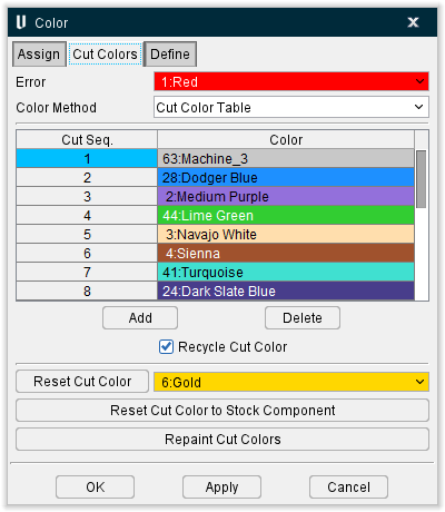
Cut Seq. / Color list — List of colors used for material cut with a safe cutting feed rate (less than the Fast Feed threshold). The cut color list associates colors with cut sequences in the NC program file. A new cut sequence is assumed when a tool with a different shape is loaded for cutting. All portions of the cutting tool shape are considered for differences. When the number of cut sequences exceeds the number of cut colors defined in the table, Recycle Cut Color determines the cut color for the remaining tools (see below).
Double-click on the cut sequence number in the table to edit it. Double-click on a color in the table and select from the pull-down color list to change a color. Add or remove colors from the pull-down list using the Shade Colors list feature on the Color window, Define tab.
Add — Use to add Cut Sequences/Colors to the list.
Delete — Use to delete Cut Sequences/Colors from the list.
Recycle Cut Color — When selected, recycles colors in the cut color list when the tool path contains more tools than cut colors defined. For example, assume that 4 cut colors are defined. When tool 5 is encountered Vericut recycles cut color 1, tool 6 uses cut color 2, and so on. When this option cleared, the last defined cut color is used for cut sequences that follow the last defined cut sequence color. Using the example above, tool 4, 5 and 6 would receive the cut color defined for cut sequence 4.
Reset Cut Color — Use this option to change colors of cuts in Cut Stock models (all of them) to the specified Reset Cut Color. This feature can also be accessed directly from the menu ribbon by selecting Configuration tab > Reset Cut Colors button
Reset Cut Color to Stock Component — Use this option to reset each cut stock to the original color of its parent component.
Repaint Cut Colors — Use this option to apply the cut color list to the cut stock model and database.
Tool Color — Cut color is determined by the tool color property stored in a Vericut Tool Library.
Feed Range Color — Cut color is determined by the feed rate programmed in the NC program file.
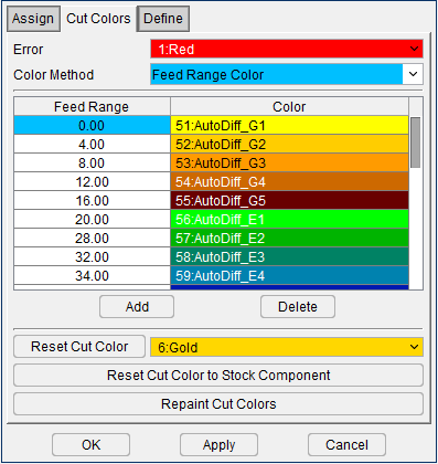
Feed Range / Color list — List of colors used for material cut within a specified feed rate range. The cut color list associates colors with feed rates in the NC program file. Using the sample table shown above, cuts using a feed rate between 0 and 25 will be displayed Aquamarine. Cuts using a feed rate between 25 and 49 will be displayed Light Steel, and so on.
Double-click on the Feed Range number in the table to edit it. Double-click on a color in the table and select from the pull-down color list to change a color. Add or remove colors from the pull-down list using the Shade Colors list feature on the Color window, Define tab.
Add — Use to add Feed Ranges/Colors to the list.
Delete — Use to delete Feed Ranges/Colors from the list.
Recycle Cut Color — When selected, recycles colors in the cut color list when the tool path contains more tools than cut colors defined. For example, assume that 4 cut colors are defined. When tool 5 is encountered Vericut recycles cut color 1, tool 6 uses cut color 2, and so on. When this option cleared, the last defined cut color is used for cut sequences that follow the last defined cut sequence color. Using the example above, tool 4, 5 and 6 would receive the cut color defined for cut sequence 4.
NC Program File Color — Cut color is determined by the Cut Sequence/Color list defined in the Cut Color Table method described above except that the Cut Sequence changes as the NC program file changes instead of when the tool changes. If a Project file only uses one NC program file, then all cuts will be the same color.
Color window, Define tab
The features on the Define tab enable you to define the colors seen in Vericut.
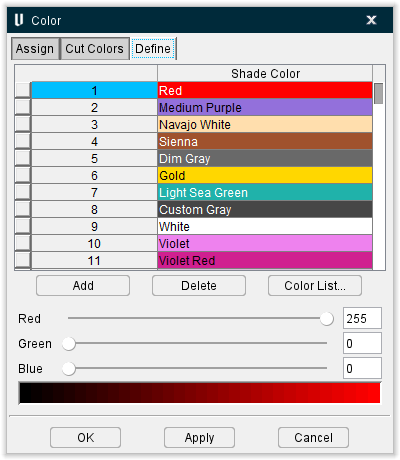
Shade Color list — List of colors that can be used to shade solid objects seen in Vericut, such as: models, cutting tools, and machined cuts (maximum 128 colors). The number of shade colors also affects shade quality. The color band at the bottom of the window displays the shade variations of the selected color in the list, as impacted by the total number of defined colors. Once defined, assign the colors to solid objects using the features on the Assign tab and the Cut Colors tab.
Add — Use to add colors to the Shade Color list.
Delete — Use to delete colors from the Shade Color list.
Red-Green-Blue slidebars — Control the amount of red, green, and blue color components mixed to define a color. The exact value is shown in the field to the right of each slidebar (0=none to 255=maximum).
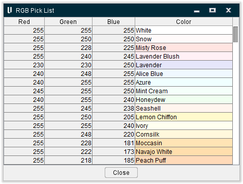
Color List — Opens a window of pre-mixed colors selectable for background, foreground, and shade colors. Click on the desired color.
RGB Pick List window
Brightness — Controls the amount of light for shading solid objects. Options are:
-
High
-
Normal
-
Low
Flat Colors group:
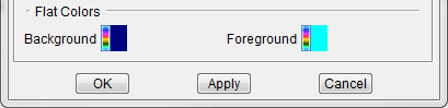
Background — Select this option to change the color of the graphics area background when View tab > Attributes: General > Background Style is set to "Flat". You can also change the background to display a shaded color, or machine views can display ceiling, floor, and walls.
Foreground — Select this option to change the color of items drawn on top of the Vericut display, for example: coordinate system axes, lines indicating the bounding region of selected models/components, etc.
The Background and Foreground colors should be different or else foreground-colored items may "blend in" with the background.