Tool Manager window, Tool Display Area
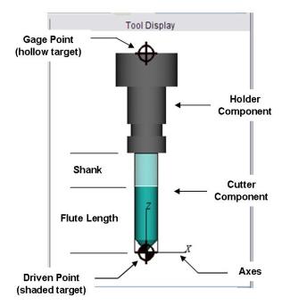
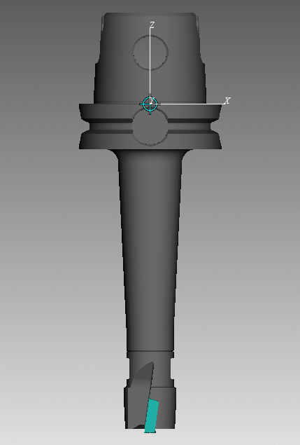
The Tool Display Area displays the tool selected in the Tool List. Colors distinguish holders from cutter components. Target symbols indicate the tool's driven point and gage point. Use the View Orient functions to visually manipulate the tool in the display area.
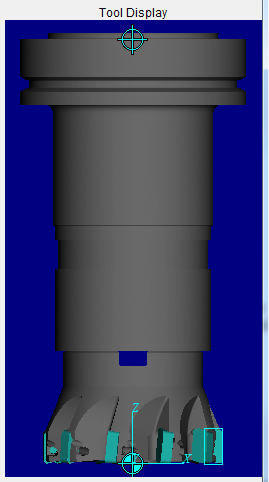
Milling Tool
CAD/STL Insert Turning Tool
↘️ Shortcuts:
-
Double click a tool component in the Tool Display area to display the appropriate Tool Component tab enabling you to make modifications to the tool component.
-
Right-click in the Tool Display area to display a menu with the following features:
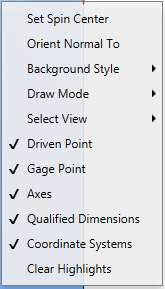
Select View — Select the view that you want from the pull-down list and the tool in the Tool Display area will re-orient to the selected view.
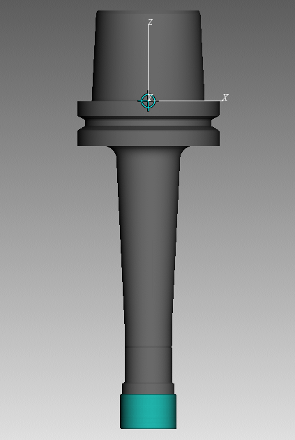
Spun Tool Display — When this option is toggled on (checked), tools in the Tool Display Area will appear as they would when they are in use. This feature will remain active until it is toggled off (unchecked) or until you exit Vericut. Spun Tool Display is off by default at the start of each Vericut session.
| Standard view | Spun Tool Display active |
|---|---|
 |
 |
Orient Normal To — Orients to the normal of a feature. See View Orient window section for more info.
Background Style — Use to specify the background style for the view. (ref. View Attributes window section of Vericut Help).
Draw Mode — Use to specify how machine components are displayed. (ref. View Attributes window section of Vericut Help).
Select View — Orients the objects in the view to the selected view. The Select View feature list will contain all available standard and custom views.
Driven Point — Use to toggle the display of the driven point symbol  , which represents the location of the driven point, “on” (checked) and “off”.
Gage Point — Use to toggle the display of the gage point symbol  , which represents the location of the gage point, “on” (checked) and “off”.
Axes — Use to toggle the display of the axis, representing the tool origin, “on” (checked) and “off”.
Qualified Dimensions — Use to toggle the display of the qualified dimensions symbol  , which represents the qualified dimension location, “on” (checked) and “off”.
Coordinate Systems — Use to toggle the display of coordinate systems available in the Tool Manager, Coordinate Systems list, “on” (checked) and “off”.
Clear Highlights — Use to remove “highlights” from the Tool Display Area.
Example:
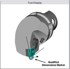
When using the X-Caliper features, if a tool component was created using a profile (Sweep Solid or Solid of Revolution) the profile will be displayed in the Tool Manager Tool Display area as shown in the picture below.
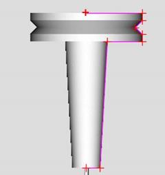
Use Clear Highlights to remove the profile when you are finished with it. The profile will automatically be removed when you change tool components.