Cutting Limits tab
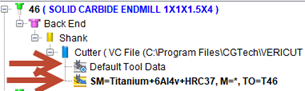
The Cutting Limits tab is displayed when optimization has been added to the tool (one of the red arrows below).
The cutting limits page is displayed when the Cutting Limits Tab is selected.
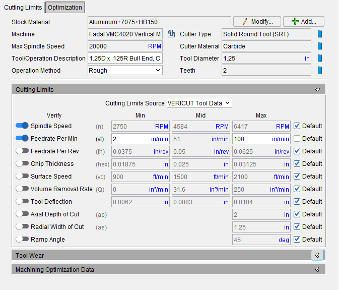
The top section of the cutting limits page provide general information of the material, machine, and cutting tool for this cutter. At the right of each information item is an icon to make changes.
Stock Material — Specifies a stock material which can be machined by this cutter. Default value from Optimize Control window “Machine”. This field cannot be left blank, or contain only spaces. This is set by the user in the Project Tree.
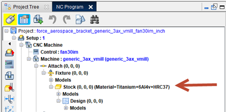
You can change the Stock Material by clicking the Change Stock Material icon ![]() to the right of this feature which will take you to the Project Tree to edit your Stock Material. You can edit the existing Stock Material Record with the use of the Modify Stock Material button
to the right of this feature which will take you to the Project Tree to edit your Stock Material. You can edit the existing Stock Material Record with the use of the Modify Stock Material button  . You can also add a new stock material by clicking the Add New Stock Material button
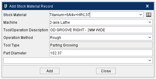
  to the right of the Change Stock Material icon. When either button is clicked, the Add or Modify Stock Material Record window opens which contains all the same info that is displayed on the Cutting Limits tab but can be edited.
Machine — Specifies an NC machine. Default value from Optimize Control window “Machine”. Selection lists show all previously defined values for that item in the TLS file, plus user can type a new value. This is also set by the user in the Optimize Control Stock Material Setting. You can click the Change Machine ![]() icon to the right of this feature to edit the Machine in the Project Tree.
icon to the right of this feature to edit the Machine in the Project Tree.
Max Spindle Speed — is set at the machine configuration level. Machine Spindle Max comes from the G-Code Processing > Start of Processing > SubSystem 1 “ActiveSpindleMaxSpeed” Value=20,000 (in this example). The limit table will use this max value in the calculations for the limits. Meaning if the NC Program attempts to use a spindle speed above the MAX (20,000 in this example) the limit values will use 20,000 in the formula as the machine can not go any higher.
Tool/Operation Description — Describes the tool and/or specific cutting operation (eg. roughing, finishing, etc.) that this record is intended to be used with. Default value is tool’s description.
Operation Method — Choose between Rough or Finish options. Rough will perform the method in a quick method while Finish will be more thorough. This only affects the Tool Performance Data where the feeds will be adjusted for roughing or finishing.
Cutter Type — Displays the type of tool being used. Solid Round Tool (SRT), or indexable tool (90d, 45d, Button, High Feed, or Ball. You can use the Change Cutter Type icon ![]() to the right of this feature to quickly edit the cutter.
to the right of this feature to quickly edit the cutter.
Cutter Material — Displays the material that the cutter is made from. You can use the Change Cutter Material icon ![]() to the right of this feature to quickly edit the cutter.
to the right of this feature to quickly edit the cutter.
Tool Diameter — Displays the diameter of the above tool in your chosen unit of measurement. You can use the Change Cutter Diameter icon ![]() to the right of this feature to quickly edit the cutter.
to the right of this feature to quickly edit the cutter.
Teeth — Number of Teeth defined for Cutter (un-editable field, shown for reference only). Go to the Tool Manager, Tool Component tab to change the number of teeth. You can use the Change Cutter Teeth icon ![]() to the right of this feature to quickly edit the cutter.
to the right of this feature to quickly edit the cutter.
Features have a toggle enabling the user to select which features should be used by toggling the feature on (slider all the way to the right) or off (slider all the way to the left) as needed. When the “Default” checkbox is toggled on (checked), the data is coming from the database. Toggled off (unchecked) means that the user may have made some manual adjustments to the data. Checking the default will return the vales from the given database and the user inputs will be lost.:
📝 NOTE: all cutting limit data is start data only. This data is moderate starting point ranges for high performance endmills in relationship to the Vericut material database.
Cutting Limits group
Cutting Limits Source — Determines where the cutting limit data (Tool Performance Data) is coming from. The preferred method would be to use imported tool data when it is available as this is expected to be the most accurate data from the cutting tool supplier. The second choice would be to use the Vericut Tool Data to obtain generic (any manufacters tool) data. If neither of these two tool data is available then Vericut will default to “Default Tool Data”.
-
Imported Tool Data — Data from the cutting tool manufacturer specific to the tool and material.
-
Vericut Tool Data — AKA Tool Performance Data (TPD) Generic tool data as it applies to the tool and material.
-
Default Tool Data — Wide range of limit data that is not specific to the tool or material.
-
📝 NOTE: The Vericut user should first try to import tool data from the cutting tool supplier or cloud tool database. This is expected to be the most accurate limit data/performance data. Vericut Tool data would be the next option when Imported Tool Data is not available.
Spindle Speed — effective spindle speed range for this cutter used in this material.
Data will come from the Vericut Tool Data or Imported Tool Data whichever is selected and available. If no data is available then the “Default” values will be used.
-
Min = Default value set by ActiveSpindleMinSpeed macro or 100 RPM.
-
Max = Default value set by ActiveSpindleMaxSpeed macro or 20,000 RPM.
Feedrate Per Min — effective feedrate range for this cutter used in this material.
Data will come from the Vericut Tool Data or Imported Tool Data whichever is selected and available. If no data is available then the “Default” values will be used.
-
Min = 1 IPM or 25 MMPM.
-
Max = depends on NC program toolpath type.
-
G-Code NC Program = 90% of the default Clean-up Feedrate. (Default Clean-up Feedrate = 50% of the setup’s Accel/Decel Max Feed Rate value for the machine's first linear component).
-
APT NC Program = 90% of the default Clean-up Feedrate (Default Clean-up Feedrate = 50% of the Fast Feed value).
Feedrate Per Rev — Data will come from the Vericut Tool Data or Imported Tool Data whichever is selected and available. If no data is available then the “Default” values will be used.
Chip Thickness — effective chip thickness range for this cutter used in this material.
Data will come from the Vericut Tool Data or Imported Tool Data whichever is selected and available. If no data is available then the “Default” values will be used.
-
Min = Feedrate "Min" / (Spindle "Max" X Number of Teeth)
-
Max = Feedrate "Max" / (Spindle "Min" X Number of Teeth)
Surface Speed — maximum surface speed for this cutter used in this material.
Data will come from the Vericut Tool Data or Imported Tool Data whichever is selected and available. If no data is available then the “Default” values will be used.
-
Min = Spindle "Min" X .262 X Cutter Diameter
-
Max = Spindle "Max" X .262 X Cutter Diameter
Volume Removal Rate — maximum volume removal rate for this cutter used in this material.
- Max = Feedrate max (IPM) X Axial Depth of Cut max X Radial Width of Cut max cutting performance limits.
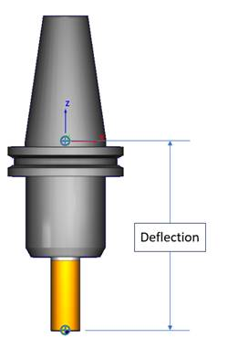
Tool Deflection — Tool deflection is automatically calculated to prevent excessive tool chatter. For users that have a Force Optimization license the max tool deflection value will automatically be assigned to the optimization settings tool deflection field and default to “ignore.” It is up to the user to set to “limit” or “warn.”
When a holder is provided in the tool assembly
The deflection is calculated from the tip of the tool up to the spindle gauge point.
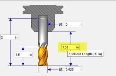
When no holder is provided only the cutter
The deflection is calculated from the tool tip to the stick out length (1.58 in the example below).
The deflection is calculated from the tip of the tool up to the spindle gauge point.
The Min tool deflection is in reality zero (“0”) but for reference it is calculated from the chip thickness. Min/Mid/Max chip thickness * .3333. example: .004’ hex * .3333 = 0.0013” Max deflection.
📝 NOTE: A Force optimization license is needed to limit or graph the tool deflection data. Also the stock material assigned to the project must be in the Vericut stock material catalog.
Non-Force users: Vericut users can use the min/mid/max deflection values as validation when manually modifying the chip thickness.
Axial Depth Cut — maximum depth of cut for this cutter used in this material.
- Max = Cutter Flute Length.
Radial Width of Cut — maximum width of cut for this cutter used in this material.
- Max = Cutter Diameter.
📝 NOTE: For Turning cutter Cutting limits, Radial Width of Cut becomes Radial Depth of Cut.
Ramp Angle — sets the limit angle for ramping.
Message Area — Informs users when material cannot be added to the record.
Add — use to create a new Stock Material Record.
Close — closes the Add Stock Material Record window without making any changes.
📝 NOTE: An additional way to access the Add Stock Material Record window is to right-click in the Tool List Area and select Add Stock Material from the right mouse button menu that displays.
Once the material has been added, the Cutting Limits tab displays containing the following information:
Stock Material, Machine, Cutter Type, Machine Max Spindle Speed, Units, Tool/Operation Description, Tool Diameter, Operation Method, and Teeth are all un-editable fields shown for reference. These values can be altered by right-clicking the stock material record in the Tool List Area and selected Edit from the right mouse button menu that displays.
Tool Wear
Cut Time — the time it took to cut displayed in minutes.
Cut Distance — the amount of distance cut displayed in the user's selected units.
Cut Volume — the amount of volume cut displayed in the user's selected units.
Reset Tool Wear limits when any active wear limit is exceeded — toggle this option on (toggle to the right) to enable Vericut to warn about when and where a tool is expected to wear out in any loaded NC Program.
📝 NOTE: Vericut does not automatically add the aforementioned tool changes into the NC program- that is left for the user to manage.
Machining Optimizing Data
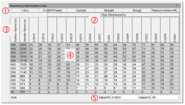
The Machining Optimization Data (MOD) is a table showing the performance data (also known as capacity data) of the given cutting tool and material to be cut. The intention of the MOD table is to give the Vericut user a much more visual display of the target values and limits. This will help the Vericut Optimizer, programmer, and machinist with data driven decisions when making speed and or feed adjustments.
Speed (vc) RPM (n), chip thickness (fz) and feedrates (fn) in a table format which can be very helpful when optimizing a tool and material for ideal performance.
A comparison of the existing NC Program values (S) & (F) can be reviewed with this table to see if it falls within the performance recommendation for this cutting tool and material.
💡 Tip: A screenshot of this table could be printed and taken to the machine for cutting tool / material testing research to find the ideal cutting parameters. The NC Program RPM (S) & Feed (F).
📝 NOTE: this table is a display of the cutting limit data and there are no manual adjustments available except for the Adjust Fz and Adjust Vc which functions are described below.
-
Header Information including:
a. Cutting Tool Diameter
b. Cutting Tool number of teeth / cutting tool flutes / number of inserts
c. Cutting Tool Material (Carbide/HSS/Cobalt/Ceramic)
d. Cutting Tool Edge Type (Straight/Serrated)
e. Cutting Tool Operation Method (Rough/Finish)
f. Stock Material (FMC Material type & hardness)
-
Chip Thickness (Fz) Feed Per Tooth
a. Values centered around the Mid start value (0.004) in this example.
-
Surface Speed and Spindle Speed in a vertical list
a. Values centered around the Mid start value (Vc 250/n 955) in this example.
-
The body of the table is feedrates in feed per min, IPM this example and would be mm/m for metric. It is very useful to use the MOD table to quickly see where the current NC Program is in relationship to the suggested start value.
a. Notice 22 IPM is the mid start point feedrate at the center of the table.
b. The light gray area is the performance window (area limited by the Fz & Vc limits). This is the expected area for the cutting tool to be successful in this material.
-
Table Adjust options. As mentioned in “Definitions” These settings allow the user to adjust the table scale where the preferred view is: 1. Have the data centered and 2. Have 3-4 columns & rows around the centered value.
📝 NOTE: these setting Adjust settings change the how the data is displayed (Fz & Vc increment values).
Using the MOD Table
Verify where the existing program performance is located in the performance window (or not). Find the Feed (F) and speed (S) in the NC Program for this cutting tool and locate in the MOD Table.
For example: let’s say the NC Program was as follows:
0060 M06 T0701

N0070 G15 H1

N0080 G00 X-.7958 Y-.2003 S955 M03

N0090 G56 Z.5112 HA

N0100 Z-1.4

N0110 G01 Z-1.5 F22. M08
Look down the spindle speed column and find the NC Program (S955) nearest Spindle Speed value in the table. Now look across the table and find the nearest Feed Rate value (F22).
Notice that this happens to be in the center of the performance window indicating that this is a good starting point. Look up the F22 column and notice the Fz value is 0.004.
This would indicate that a good chip thickness starting point would be 0.004” for optimization and it may be possible to run up to 0.005”
Also notice potential improvement that according to the data that it might be possible to double this feed to (44-45 IPM) if the Spindle speed is increased to (1528).