Transitions Path card
Transitions Path card, Transition tab
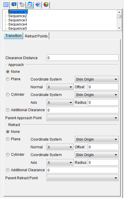
Clearance Distance — Defines the distance needed between the tool tip and the skin for the tool tip to clear any fixtures or holders.
Approach — Defines the path used by the tool to approach the material.
-
None — No approach path is defined for the tool relative to the material.
-
Plane — Use to define a plane as the approach path relative to the coordinate system, axis, and offset you select. For example, for a flat surface, you could define an approach path as a plane parallel to the skin surface.
-
Coordinate System — Use to define the coordinate system to be used to define the approach path relative to the model. The Coordinate System pull-down list enables you to select the coordinate system that you want to use.
-
Normal — Use to specify the plane orientation relative to the coordinate system. Standard options include the orientations of the three axes of the selected coordinate system.
-
Offset — Use to specify a distance between the origin of the selected coordinate system and the specified plane.
-
Cylinder — Use to define a cylinder relative to the coordinate system, axis, and radius you select.
-
Coordinate System — Use to define the coordinate system to be used to define the approach path relative to the model. The Coordinate System pull-down list enables you to select the coordinate system that you want to use.
-
Axis — Enables you to specify the axis of the cylinder by selecting the X, Y, or Z axis of the coordinate system. To change the current axis, simply select it from the pull-down list.
-
Radius — Enables you to specify the radius of the cylinder.
-
Additional Clearance — Defines any additional clearance needed between the tool tip and the skin for the tool tip to clear any fixtures or holders.
-
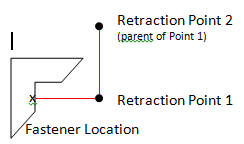
Parent Retract Point — If you are defining a complex transition path, you will create a series of retract points with a parent/child relationship. The drop-down displays a list of retract points that have been defined for the selected sequence. Select the retract point that is the parent of the retract point you are defining.
Retract — Defines the path used by the tool to retract from the material.
-
None — No retract path is defined for the tool relative to the material.
-
Plane — Use to define a plane as the retract path relative to the coordinate system, axis, and offset you select.
-
Coordinate System — Use to define the coordinate system to be used to define the retract path relative to the model. The Coordinate System pull-down list enables you to select the coordinate system that you want to use.
-
Normal — Use to specify the plane orientation relative to the coordinate system. Standard options include the orientations of the three axes of the selected coordinate system.
-
Offset — Use to specify a distance between the origin of the selected coordinate system and the specified plane.
-
Cylinder — Use to define a cylinder relative to the coordinate system, axis, and radius you select.
-
Coordinate System — Use to define the coordinate system to be used to define the retract path relative to the model. The Coordinate System pull-down list enables you to select the coordinate system that you want to use.
-
Axis — Enables you to specify the axis of the cylinder by selecting the X, Y, or Z axis of the coordinate system. To change the current axis, simply select it from the pull-down list.
-
Radius — Enables you to specify the radius of the cylinder.
-
Additional Clearance — Defines any additional clearance needed between the tool tip and the skin for the tool tip to clear any fixtures or holders.
-
Parent Retract Point — If you are defining a complex transition path, you will create a series of retract points with a parent/child relationship. The drop-down displays a list of retract points that have been defined for the selected sequence. Select the retract point that is the parent of the retract point you are defining.
Transition Paths card, Retract Points tab
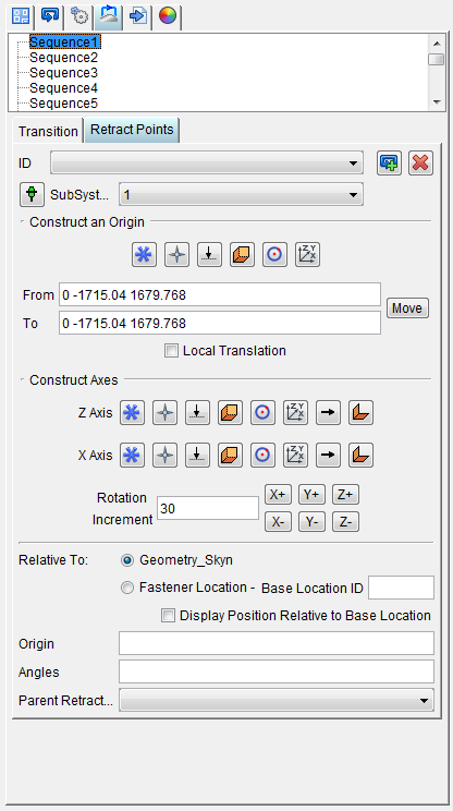
ID — Displays a list of retract points that have been defined for the sequence.
 (Create a new retract point) — Adds a new retract point to the NC program. The retract point is named “RetractPoint” followed by an incremental numeric value.
 (Delete current retract point) — Deletes the current retract point from the NC program.
 (Create a new retract point at current tool tip zero) — Adds a new retract point to the NC program positioned at tool tip zero.
Construct an Origin — For the retract point, you will define a coordinate system to specify the location of the retract point. Use the buttons to define the origin for the retract point.
-
 (Construct an origin by picking a fastener location) — Enables you to select a fastener location on the graphics view as the retract origin.
 -
 (Construct an origin by picking a point on a model) — Enables you to select a point on the model in the graphics view as the retract origin.
 -
 (Construct an origin at the intersection of a vector and a plane) — Enables you to define the retract origin by selecting a vector and a plane in the graphics area.
 -
 (Construct an origin at the intersection of three planes) — Enables you to define the retract origin by selecting the intersection of three planes in the graphics area.
 -
 (Construct an origin at the center of a circle) — Enables you to select the center of a circle in the graphics view as the retract origin.
 -
 (Construct and origin at the origin of a coordinate system) — Enables you to select the origin of a coordinate system in the graphics view as the retract origin.
From / To — Use the From and To text fields to specify the "from" point, and the "to" point, to be used for moving the CSYS. XYZ values can be entered (separated by spaces), or selected by clicking in the field then clicking on a model. As you move the mouse over the Vericut model, a crosshair and vector show you the pending pick-point location. Graphical selection supports picking corner points and midpoints of uncut model geometry, or virtually any point on machined features or tool assembly features.
When working in the Project Tree, Configure Coordinate System menu the From and To points are relative to the workpiece origin.
When working in the Tool Manager, Configure Coordinate System menu, the From and To points are relative to the tool origin.
Move — Moves the selected CSYS by the incremental distance, as calculated from the "From" point to the "To" point location.
Local Translation — When toggled "on", From/To values are relative to the current CSYS.
📝 NOTE: This feature is useful when trying to align a CSYS to the center of a machined hole.
Construct Axes — For the retract point, you will define a coordinate system to specify the location of the retract point. Use the buttons to define the Z and X axes for the retract point.
-
Z Axis —
-
(Construct an axis from retract point origin to a picked fastener location) — Enables you to create the Z axis based on the retract point origin and a selected fastener location on the graphics view.
-
(Construct an axis from retract point origin to a picked point on a model) — Enables you to create the Z axis based on the retract point origin and a selected point on the model in the graphics view.
-
(Construct an axis from retract point origin to the intersection of a vector and a plane) — Enables you to define the Z axis based on the retract origin and selecting a vector and a plane in the graphics area.
-
(Construct an axis from retract point origin to the intersection of three planes) — Enables you to define the Z axis based on the retract origin and selecting three planes in the graphics area.
-
(Construct an axis from retract point origin to the center of a circle) — Enables you to define the Z axis based on the retract origin and selecting the center of a circle in the graphics area.
-
(Construct an axis from retract point origin to the origin of a coordinate system) — Enables you to create the Z axis based on the retract point origin and the origin of a coordinate system in the graphics area.
-
 (Construct an axis by picking a vector) — Enables you to create the Z axis by selecting a vector in the graphics area.
 -
 (Construct an axis using the intersecting vector of two planes) — Enables you to create the Z axis by selecting the intersecting vector of two planes in the graphics area.
 -
X Axis —
-
(Construct an axis from retract point origin to a picked fastener location) — Enables you to create the X axis based on the retract point origin and a selected fastener location on the graphics view.
-
(Construct an axis from retract point origin to a picked point on a model) — Enables you to create the X axis based on the retract point origin and a selected point on the model in the graphics view.
-
(Construct an axis from retract point origin to the intersection of a vector and a plane) — Enables you to define the X axis based on the retract origin and selecting a vector and a plane in the graphics area.
-
(Construct an axis from retract point origin to the intersection of three planes) — Enables you to define the X axis based on the retract origin and selecting three planes in the graphics area.
-
(Construct an axis from retract point origin to the center of a circle) — Enables you to define the X axis based on the retract origin and selecting the center of a circle in the graphics area.
-
(Construct an axis from retract point origin to the origin of a coordinate system) — Enables you to create the X axis based on the retract point origin and the origin of a coordinate system in the graphics area.
-
(Construct an axis by picking a vector) — Enables you to create the X axis by selecting a vector in the graphics area.
-
(Construct an axis using the intersecting vector of two planes) — Enables you to create the X axis by selecting the intersecting vector of two planes in the graphics area.
-
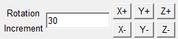
Rotation Increment — Degrees of incremental rotation to apply when a rotation button is pressed (see below). Enter the Rotation Increment value in the text field.
-
Rotation buttons (X+/X-, Y+/Y-, Z+/Z-) — axis and direction in which to apply the incremental rotation angle specified by the Rotation Increment value.
Relative To — For the retract point, you will define a coordinate system to specify the location of the retract point. Use the options below to specify the relative position of the retract point.
-
Skin Origin — When selected, the retract point location will be oriented relative to the skin origin.
-
Fastener Location — When selected, the retract point location will be oriented relative to a fastener you select.
-
Display Position Relative to Base Location — When selected the graphic area will display the retract point relative to the base location.
Angles — The angles of orientation of the retract point.
Parent Retract Point — If you are defining a complex transition path, you will create a series of retract points with a parent/child relationship. The drop-down displays a list of retract points that have been defined for the selected sequence. Select the retract point that is the parent of the retract point you are defining.