Configure Simulated Locations menu
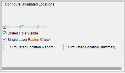
Inserted Fastener Visible — Use to turn the display of inserted fasteners "on" (checked), and "off", in the graphics area.
Drilled Hole Visible — Use to turn the display of drilled holes "on" (checked), and "off", in the graphics area.
Single Layer Fasten Check — Toggles on (checked) and off single layer checking enabling you to simulate fasteners inserted into a single skin layer without errors.
Simulated Location Report — Use to display the Simulated Location Report panel which provides detailed simulated location and fastener information.
Simulated Location Summary — Use to display a Simulated Location Summary panel which provides summary information for each simulated drilled hole and fastener.
Simulated Location Report panel
The Simulated Location Report panel is a table containing all simulated location data. Each row in the table represents a drilled hole/fastener location.
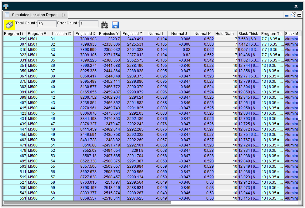
When a row is selected in the Simulated Location Report panel it becomes highlighted in the table, the corresponded drilled hole/fastener location in the graphics window becomes highlighted and the corresponding NC program record in the NC Program panel becomes highlighted. You can also select a drilled hole/fastener location in the graphics window and the corresponding row in the Simulated Location Report panel and the corresponding NC program record in the NC Program panel become highlighted.
The Simulated Location Report panel is one of the dockable panels enabling you to dock it inside the Vericut Drill and Fastener Simulation main window if you choose.
📝 NOTE: When the Simulated Location Report panel is docked, make sure that you click in the panel so that it becomes the "active" panel before using F1 to get help specific to the panel. Otherwise F1 will go to the Vericut Help Library.
![]() (Close) — Located at the end of the tab, this icon enables you to close the Simulated Location Report panel.
(Close) — Located at the end of the tab, this icon enables you to close the Simulated Location Report panel.
![]() (Close) — Closes the Simulated Location Report panel. This icon is only displayed when the Status panel is not docked.
(Close) — Closes the Simulated Location Report panel. This icon is only displayed when the Status panel is not docked.
Simulated Location Report window features
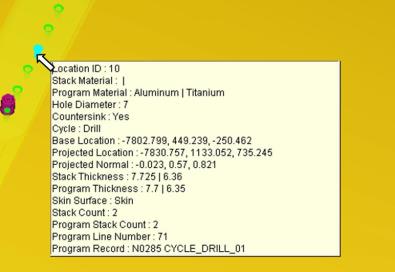
![]() (Mouse Pick Indicator) — When highlighted, the Mouse Pick Indicator indicates that the Simulated Location Report panel is the "active" window. When highlighted, holding the cursor over a drilled hole/fastener location, in the graphics window, will highlight the location and display information specific to the particular location as shown in the picture below.
(Mouse Pick Indicator) — When highlighted, the Mouse Pick Indicator indicates that the Simulated Location Report panel is the "active" window. When highlighted, holding the cursor over a drilled hole/fastener location, in the graphics window, will highlight the location and display information specific to the particular location as shown in the picture below.
See Mouse Pick Indicator in the Getting Started section of Vericut Drill and Fastener Simulation Help for additional information.
Total Count — Displays the total count of drilled hole/fastener locations that have been processed and appear in the table.
Error Count — Displays the number of drilled hole/fastener locations that have errors associated with them.
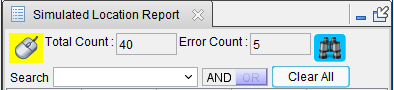
![]() (Search) — Clicking on the Search icon displays the Simulated Location Report search tool in the upper left corner of the window to assist you in finding the information that you need in the Simulated Location Report Table. Initially the search tool will display as shown in the following picture.
(Search) — Clicking on the Search icon displays the Simulated Location Report search tool in the upper left corner of the window to assist you in finding the information that you need in the Simulated Location Report Table. Initially the search tool will display as shown in the following picture.
Search — The Search pull-down list contains all of the search categories that are available. Each of the categories corresponds to a column header in the Simulated Location Report Table. Each of these categories will be described in the Simulated Location Report Table section below.
Selecting a category will change the way that the search tool looks depending on the supporting information needed to conduct the search. An And Search/Or Search pull-down list, depending on the AND / OR setting, is also automatically added. Each of these features is described below. The search tool will look similar to one of the following pictures.
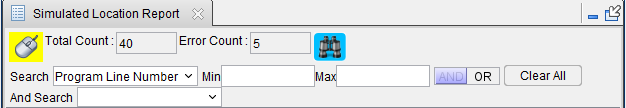
Min/Max — use the Min and/or Max fields to specify a number, or range of numbers, associated with the selected search category to define the bounds of the search. The result of using different Min/Max combinations is described below.
Entering a Min value and a Max value will display all rows between the Min value and the Max value including the specified values.
Entering a Min value that does not exist will display the row with closest larger value than the one specified.
Entering the same Min and Max values will display the row with the specific value specified.
Entering a Min value and a blank Max value will display all rows with values greater than or equal to the specified Min value.
Entering a blank Min value and a Max value will display all rows with values less than or equal to the specified Max value.
text field — use the text field to enter a text string associated with the selected search category to define the bounds of the search. The result of using different text strings in the text field is described below for each search category that uses a text field.
AND / OR — use AND or OR to specify multiple conditions for the search. AND indicates that if both conditions are met, include the row in the resulting list. OR indicates that if either of the condition is met, include the row in the resulting list.
Clear All — use to clear all entered search parameters and return the search tool to its initial state.
And Search / Or Search — these features work in the same way as the Search feature described above.
Using Each Search Category
Program Line Number — Use the Min and Max fields to specify the range of line numbers that you want displayed.
Program Record — Use the text field to enter a Program Record, or part of the Program Record to be used for the search.
Examples:
Program Record = N0345 CYCLE_ID05

  Entering N03 in the text field will list all rows containing the N03 text string:

    N0305 CYCLE_DRILL_01

    N0325 CYCLE_DRILL_02

    N0345 CYCLE_ID05

  Entering CYCLE_ID05 in the text field will list all rows containing the CYCLE_ID05 text string:

    N0105 CYCLE_ID05

    N0225 CYCLE_ID05

    N0345 CYCLE_ID05
Location ID — Use the text field to enter a Location ID, or part of the Location ID to be used for the search.
Examples:
-
Entering 15 in the text field will list all rows containing the 15 text string (15, 115, 150, etc.).
-
Entering 22 in the text field will list all rows containing the 22 text string (22, 122, 220, 221, 222, etc.).
Projected X — Use the Min and Max fields to specify the range of Projected X values that you want displayed in the table.
Projected Y — Use the Min and Max fields to specify the range of Projected Y values that you want displayed in the table.
Projected Z — Use the Min and Max fields to specify the range of Projected Z values that you want displayed in the table.
Normal I — Use the Min and Max fields to specify the range of Normal I values that you want displayed in the table.
Normal J — Use the Min and Max fields to define the range of Normal J values that you want displayed in the table.
Normal K — Use Min and Max fields to define the range of Normal K values that you want displayed in the table.
Hole Diameter — Use Min and Max fields to define the range of Hole Diameter values that you want displayed in the table.
Stack Thickness — Use the text field to enter a Stack Thickness, or part of a Stack Thickness text string, to be used for the search.
Example:
For a Stack Thickness value of 7.632 | 6.351, the 7.632 is the "Skin" stack thickness and 6.351 is the "Structure" stack thickness.
You can use any part, or all, of the "Skin" stack thickness text string or any part, or all, of the "Structure" stack thickness text string for searching.
Entering 49 in the text field will list all rows containing the 49 text string in either the "Skin" or "Structure" stack thickness or both the "Skin" and "Structure" stack thickness.
11.649 | 6.353

7.774 | 6.349

7.496 | 6.349

      etc.
Program Thickness — Use the text field to enter a Program Thickness, or part of a Program Thickness text string, to be used for the search. This feature works the same way as Stack Thickness. See the example for Stack Thickness above.
Stack Material — Use the text field to enter a Stack Material, or part of a Stack Material text string, to be used for the search.
Example:
For a Stack Material value of Aluminum | Titanium, Aluminum is the "Skin" stack material and Titanium is the "Structure" stack material.
You can use any part, or all, of the "Skin" stack material text string or any part, or all, of the "Structure" stack material text string for searching. For example Aluminum and Alum will provide the same result as long as the Simulated Location Report table does not contain another Stack Material that begins with Alum.
Entering Aluminum in the text field will list all rows containing the Aluminum text string in either the "Skin" or "Structure" stack material or both the "Skin" and "Structure" stack material.
Aluminum | Titanium

Aluminum | Composite

Aluminum | Aluminum

        etc.
Entering Aluminum | Titanium in the text field will list all rows containing the Aluminum | Titanium text string.
Program Material — Use the text field to enter a Program Material, or part of a Program Material, to be used for the search. This feature works the same way as Stack Thickness. See the example for Stack Material above.
Stack Count — Use the Min and Max fields to define the range of Stack Count values that you want displayed in the table.
Program Stack Count — Use the Min and Max fields to define the range of Program Stack Count values that you want displayed in the table.
Countersink — Select No from the pull-down list to display all rows that have the Countersink checkbox toggled off (not checked). Select Yes from the pull-down list to display all rows that have the Countersink checkbox toggled on (checked).
Fastener ID — Use the text field to enter a Fastener ID, or part of a Fastener ID text string, to be used for the search.
Examples:
Entering 1 in the text field will list all rows containing the 1 text string (1, 15, 115, 150, etc.).
Entering 22 in the text field will list all rows containing the 22 text string (22, 122, 220, 221, 222, etc.).
Fastener Type — Select Not Defined, Temporary or Permanent from the pull-down list. All rows with the specified Fastener Type will be displayed.
Error Message — Use the text field to enter a key word, or words, from an error message to define the type of errors that you want displayed in the list. For example, fastener, material, countersink, stack count, etc.
Cycle — Use the text field to enter a Cycle, or part of a Cycle text string, to be used for the search.
Simulated Location Report table — The Simulated Location Report table consists of 22 columns of information related to each drilled hole/fastener location represented in the table. Each row represents an individual drilled hole/fastener location.
The information for columns with a  background comes from the NC program. The information for columns with a
  background comes from the simulation.
Program Line Number — The program line number is the line number shown in the NC Program panel (Info > NC Program) when a drill/fastener cycle is executed at the current drilled hole/fastener location.
Program Record — The NC program record that was executed at the current drilled hole/fastener location. For example, N0105 CYCLE_ID05.
Location ID — The location ID specified in the NC program for the current drilled hole/fastener location.
Projected X — The X component of the vector representing the projection of the active tool component, along its z-axis, to the current drilled hole/fastener location on skin component.
Projected Y — The Y component of the vector representing the projection of the active tool component, along its z-axis, to the current drilled hole/fastener location on skin component.
Projected Z — The Z component of the vector representing the projection of the active tool component, along its z-axis, to the current drilled hole/fastener location on skin component.
Normal I — The I component of the surface normal vector of the skin component at the current drilled hole/fastener location.
Normal J — The J component of the surface normal vector of the skin component at the current drilled hole/fastener location.
Normal K — The K component of the surface normal vector of the skin component at the current drilled hole/fastener location.
Hole Diameter — The hole diameter at the current drilled hole/fastener location.
Stack Thickness — The stack thickness calculated from model thickness at the current drilled hole/fastener location. The Stack Thickness value in the Simulated Location Report table includes both the "Skin" stack thickness and the "Structure" stack thickness. For a Stack Thickness value of 7.632 | 6.351, the 7.632 is the "Skin" stack thickness and 6.351 is the "Structure" stack thickness.
Program Thickness — The stack thickness specified in the NC program at the current drilled hole/fastener location. The Program Thickness value in the Simulated Location Report table includes both the "Skin" stack thickness and the "Structure" stack thickness. For a Program Thickness value of 7.7 | 6.35, the 7.7 is the "Skin" stack thickness and 6.35 is the "Structure" stack thickness.
Stack Material — The stack material defined in the Project file for the current drilled hole/fastener location. The Stack Material value in the Simulated Location Report table includes both the "Skin" stack material and the "Structure" stack material. For a Stack Material value of Aluminum | Titanium, Aluminum is the "Skin" stack material and Titanium is the "Structure" stack material.
Program Material — The stack material defined in the NC program for the current drilled hole/fastener location. The Program Material value in the Simulated Location Report table includes both the "Skin" stack material and the "Structure" stack material. For a Stack Material value of Aluminum | Titanium, Aluminum is the "Skin" stack material and Titanium is the "Structure" stack material.
Stack Count — The stack count is the total number of layers specified in the Project file at the current drilled hole/fastener location. The stack count includes the "Skin" layer and one or more "Structure" layers.
Program Stack Count — The program stack count is the total number of layers specified in the NC program at the current drilled hole/fastener location. The stack count includes the "Skin" layer and one or more "Structure" layers.
Countersink — The countersink status of the hole, specified in the NC program, for the current drilled hole/fastener location. A check in the box indicates a countersunk hole. No check indicates that the hole is not countersunk.
Fastener ID — The fastener ID identifies the fastener specified in the NC program that is to be used at the current drilled hole/fastener location. A blank fastener ID field would indicate just a drilled hole at the current location.
Fastener Type — The fastener type indicates the type of fastener being used at the current drilled hole/fastener location.
Undefined — A blank fastener type field indicates that the type for fastener being used at the current location was not defined in the NC program.
Temporary — Temporary indicates that the fastener being used at the current location is a temporary fastener that will be replaced in a downstream operation.
Permanent — Permanent indicates that a permanent fastener is being used at the current drilled hole/fastener location.
Error — Provides a visual indication that an error has occurred at the current drilled hole/fastener location. The![]() symbol in the error field indicates that an error has occurred.
symbol in the error field indicates that an error has occurred.
Error Message — The text in the error message field describes the error that occurred at the current drilled hole/fastener location. For example, "Fastener 1's countersink type does not match hole's at line 101."
Cycle — The cycle field indicates the type of cycle that was executed at the current drilled hole/fastener location. For example, "Drill", or "Drill and Insert".
Simulated Location Report Window Right Mouse Button Menu
The features in the Simulated Location Report window, right mouse button menu enable you to display the Simulated Location Report search tool as well as providing tools that enable you to configure the Simulated Location Report table in a manner that best suits your specific needs.
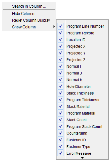
Search in Column — Displays the Simulated Location Report search tool in the upper left corner of the window. Provides the same functionality as the Search icon ![]() described above.
described above.
Hide Column — Enables you to hide columns in the Simulated Location Report table. Click with the right mouse button in the column that you want to hide and then select Hide Column from the menu that displays.
Reset Column Display — Enables you to reset the columns in the Simulated Location Report table to the default condition (all columns displayed).
Show Column — Clicking on Show Column displays a list of all columns available for display in the Simulated Location Report table and its current status. A check next to an item indicates that the item is currently displayed in the Simulated Location Report table. Click on an item in the list to toggle between displayed (checked) and a not displayed.
When displaying a column, right click in the column to the right of the location where you want the column displayed to display the menu. When you select the column that you want displayed, it will be inserted immediately to the left of the column you opened the menu in.
Hold the cursor over the ![]() at the bottom of the list to view additional columns.
at the bottom of the list to view additional columns.
💡 Tips:
-
If the column did not get displayed where you wanted, click in the column header and drag the column to the right, or left, to the desired position. You can do this with any column, at any time.
-
You can change the width of each column by clicking on the divider between headers and then moving the divider to the left or right to make the column width smaller or larger
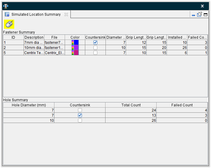
Simulated Location Summary panel
The Simulated Location Summary panel consists of two tables of information associated with the simulation. The Fastener Summary table provides information about the fasteners that have been inserted during the simulation. The Hole Summary table provides information specific to holes drilled during the simulation.
📝 NOTE: When the Simulated Location Summary panel is docked, make sure that you click in the panel so that it becomes the "active" panel before using F1 to get help specific to the panel. Otherwise F1 will go to the Vericut Help Library.
![]() (Close) — Located at the end of the tab, this icon enables you to close the Simulated Location Summary panel.
(Close) — Located at the end of the tab, this icon enables you to close the Simulated Location Summary panel.
![]() (Close) — Closes the Simulated Location Summary panel. This icon is only displayed when the Status panel is not docked.
(Close) — Closes the Simulated Location Summary panel. This icon is only displayed when the Status panel is not docked.
Simulated Location Summary window features
![]() (Mouse Pick Indicator) — When highlighted, the Mouse Pick Indicator indicates that the Simulated Location Summary panel is the "active" window. When highlighted, holding the cursor over a drilled hole/fastener location, in the graphics window, will highlight the location and display information specific to the particular location as shown in the picture below.
(Mouse Pick Indicator) — When highlighted, the Mouse Pick Indicator indicates that the Simulated Location Summary panel is the "active" window. When highlighted, holding the cursor over a drilled hole/fastener location, in the graphics window, will highlight the location and display information specific to the particular location as shown in the picture below.
![]() (Close) — Closes the Simulated Location Summary window.
(Close) — Closes the Simulated Location Summary window.
Fastener Summary Table — The Fastener Summary table provides information about the fasteners that have been inserted during the simulation. Each row in the table represents a summary of the following information for a specific fastener. See the Configure Fastener Model menu section for additional information.
ID — the fastener's ID.
Description — the description of the fastener
File — the filename of the Fastener Model file
Color — the color of the fastener
Countersink — indicates whether or not the fastener requires a countersunk hole. A check indicates that a countersunk hole is required.
Diameter — the diameter of the fastener
Grip Length Min. — the minimum grip length value of the fastener
Grip Length Max. — the maximum grip length value of the fastener
Installed Count — the number of fasteners installed during the simulation
Failed Count — the number of fastener installations that failed during the simulation.
Hole Summary Table — The Hole Summary table provides information specific to holes drilled during the simulation. Each row in the table represents a summary of the following information for a specific drilled hole size.
Hole Diameter — the diameter of the drilled hole
Countersink — indicates whether or not the drilled hole has been countersunk. A check indicates a countersunk hole.
Total Count — the total number of holes that were drilled during the simulation
Failed Count — the number of hole drilling operations that failed during the simulation.
💡 Tips:
-
You can change the position of a column by clicking in the column header and drag the column to the right, or left, to the desired position.
-
You can change the width of each column by clicking on the divider between headers and then moving the divider to the left or right to make the column width smaller or larger.