Configure NC Programs Branch menu
Location:
Project Tree > NC Programs branch (Configure “on”)
Opened by selecting an NC Programs Branch in the Project Tree, the Configure NC Programs menu enables you to specify the NC Program Type and add NC programs to the NC Programs branch. The Configure NC Programs menu will display differently depending on the selected NC Program Type as shown below.
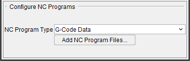
NC Program Type — Type of NC program file for Vericut to simulate. By default, Vericut simulates G-Code or "machine code data" NC programs destined for a 3-axis mill machine with a "Fanuc-like" control. Using this option, you can quickly configure Vericut to simulate NC programs from all popular CAM systems. Options:
-
G-Code Data — G-Code NC program file. With this choice, Vericut uses a Machine file, Control file, and G-Code settings (ref. Project tab > Settings > G-Code Advanced Settings) to interpret codes present in the file.
-
Vericut APT — Generic ASCII APT NC program file from virtually any source, including ACL format.
-
UG CLS — UG CLS NC program file.
-
CATIA APT — CATIA APT source NC program file. This file must be processed from CATIA using the CATUTIL function and typically has a ".APTSOURCE" extension.
-
CV APT — ComputerVision APT NC program file.
-
CADRA APT — CADRA APT NC program file.
-
APT (RevPost) — ASCII APT NC program file created from reverse post-processing G-Code data.
-
Pro/MFG APT — Pro/Manufacturing APT NC program file.
-
NCL APT — NCL APT NC program file.
-
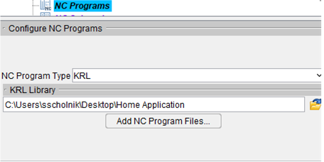
KRL — Displays the following Configure NC Programs menu:
-
KRL Library — The location of the folder containing KRL library files for this project.
The following picture is representative of the Configure NC Programs menu for all of the above NC program types.
Add NC Program Files — Opens the NC Programs file selection window enabling you to add one or more NC program files to the list.
Siemens VNC 840D — Displays the following Configure NC Programs menu.
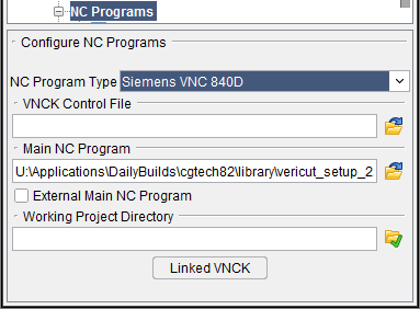
VNCK Control File — Selects a DAT, ARC, VMF, or INI file from the konfig.dir folder associated with the machine and project being simulated. As described above, a SRAM (.dat) file is recommended, however ARC and INI files can also be directly used.
Main NC Program (MPF) — Selects the NC program being simulated. The main program must have an "mpf" extension and should reside in the "project.wpd" folder if it is not an external MPF. In Linked VNCK mode, this field is de-sensitized. The NC program must be defined from the HMI application.
External MPF — Indicates the MPF does not reside in the WPD folder. The 840D has additional restrictions regarding "external files" defined in Siemens’ documentation.
Working Project Directory — Select the WPD folder for the application being simulated. Note that this folder must have a ".wpd" appended to its name and must have the same parent folder as the "konfig.dir" folder. In Linked VNCK mode, the project is sent to the VNCK server. VNCK loads all of the MPF and SPF files for NC Program selection.
Linked VNCK — Launches the VMCP panel for simulation with HMI advanced.
Stop VNCK — This button will kill the VNCK process. It should only be used if communications between Vericut and the VNCK is lost. This button is added to the VCR control panel next to the reset button when a VNCK related file is in use.
See 840D Virtual NC Kernel and Interface (VNCK) in the Converters and CAD/CAM Interfaces section of the Vericut Help Library for additional information.
In addition to the NC program types above, Vericut's converters enable you to simulate NC programs from various CAM systems. See the "Binary Converter" topic in the Converters and CAD/Cam Interfaces section of the Vericut Help Library.
See Add, Modify, or Delete NC Programs section below for additional information.
VNCK Machine Control Panel (VMCP)
This panel controls the VNCK server and the Vericut simulation. When this panel is ON, the regular Vericut VCR buttons disappear and show the “Stop VNCK” button. This panel works with a combination of VNCK server and HMI interface. Usually the first step is to Boot the VNCK server. After booting, the second step is to launch HMI.
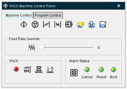
Machine Control tab
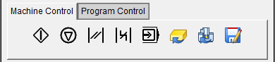
| ICON | NAME | Function |
|---|---|---|
  |
Program Start | Sends an event to the VNCK server. It runs the selected NC program. Green icon indicates that the simulation is running. |
 |
Program Stop | Stops the simulation. |
 |
Program Reset | Resets the VNCK server. |
 |
Bag Reset | Resets the VNCK server with a BAG event. |
  |
Single Step | Moves the simulation forward by a single step. Green icon indicates Single Step mode is active. |
 |
Reset Material | Resets the material by displaying a new model, removing mounted tools, and relocating the machine at the end of the initial location. |
 |
Reset Kernel | Reset VNCK server and reboots it. |
| Save VMF file | Generates a Save panel. |
Program Control tab
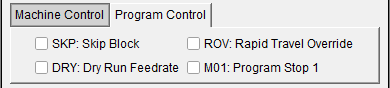
SKP — Sets simulation to Skip Block.
Dry — Sets the simulation to Dry Run mode.
ROV — Sets simulation Rapid Travel Override (Rapid Travel Override value is defined in the preset file).
M01 — Sets simulation to stop at M01.
Feed Rate Override

| ICON | NAME | Function |
|---|---|---|
  |
Feed Rate Override | Allow to override the programmed feed rate by a percentage. The slider bar is used to set the percentage. Range of percentage is defined in the VNCK Control file (ARC, SRAM, VMF). Green icon indicates Feed Rate Override is active. |
VNCK
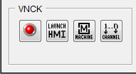
| ICON | NAME | Function |
|---|---|---|
   |
Boot | Boot the VNCK server with the selected VNCK control file (VMF file). During the Boot phase, Vericut sends the defined Working Project Folder to VNCK for NC Program selection. Yellow icon indicates booting is taking a while. Green icon indicates booting is finished. HMI launches. |
  |
Launch HMI | Launches HMI. This may take several seconds. The HMI executable must be defined in the vericut.bat file. Green icon indicates HMI is up and running. NC program (.spf) should be available in the VNC-SIM folder. |
 |
Machine | This button switches the HMI panel to Global menu (this is the same functionality as pressing the F10 key on your keyboard). |
 |
Channel | This button switches the HMI panel to a different Machine Channgel (this is the same functionality as pressing the F11 key on your keyboard). |
Alarm Status
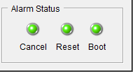
There are two are two types of alarm events: Alarm Event and Alarm Description. The Alarm Event only has the alarm type: Cancel, Reset, or Boot. The Cancel alarm event can be canceled in the code. The Reset and Boot alarms cannot be canceled in the code and VNCK must be rebooted by the user. The indicator lights can be green, yellow, or red. Green indicates that there are no alarms. Yellow indicates that the alarm is minor. Red indicates that the alarm is severe. Alarm Descriptions do not affect the indicator lights.
In Linked mode, Vericut tool definitions and offset registers are NOT passed to the VNCK during the VNCK boot phase. But this information is written to a "VericutVNCK.ini" file residing in the "konfig.dir" folder. The user would have the possibility to use it.
The user must use HMI to select NC program. According the VMF file, the user could have to define tool definitions and offset registers in HMI.
 (Stop VNCK) — This button will kill the VNCK process. It should only be used if communications between Vericut and the VNCK is lost.
See the Other Interfaces topic in the Converters and CAD/Cam Interfaces section of the Vericut Help Library for more info.
Configure NC Program menu
Location:
Project Tree > NC program (Configure “on”)
Opened by selecting an NC Program in the Project Tree, the Configure NC Program menu enables you to make the highlighted NC program Active/Inactive, assign a CSYS, edit or replace the highlighted NC program and add additional NC programs.
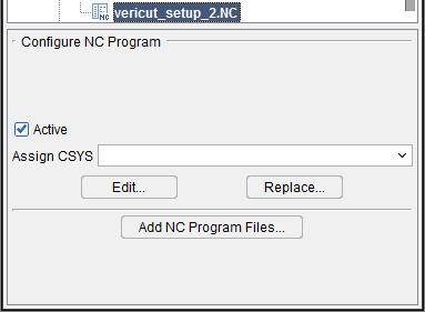
Active — When toggled “on” (checked), the highlighted NC program file is designated as “active”. When toggled “off”, the highlighted NC program file is designated as “inactive”. Only NC program files designated as “active” are processed by Vericut. "Inactive" NC program files are indicated by red text in the Project Tree panel.
Assign CSYS — Use to assign a coordinate system (CSYS) to the highlighted NC program file. Select the desired CSYS from the pull-down list. Vericut will append the selected CSYS to the NC program file in the Project Tree.
Edit — Opens the highlighted NC program in the NC Program Editor window.
Replace — Opens the NC Programs file selection window enabling you select one, or more NC programs to replace the NC program highlighted in the Project Tree.
Add NC Program Files — Opens the NC Programs file selection window enabling you to add one or more NC program files to the list.
NC Programs File Selection Window
Location:
Project Tree > Configure NC Programs menu > Add NC Program Files
The NC Programs file selection window enables you to add one or more NC program files (ref. NC Program File in the Getting Started section of Vericut Help. NC program files are ASCII text files that contain data describing cutting tool positions, machine information, and other information required to operate NC machine tools.
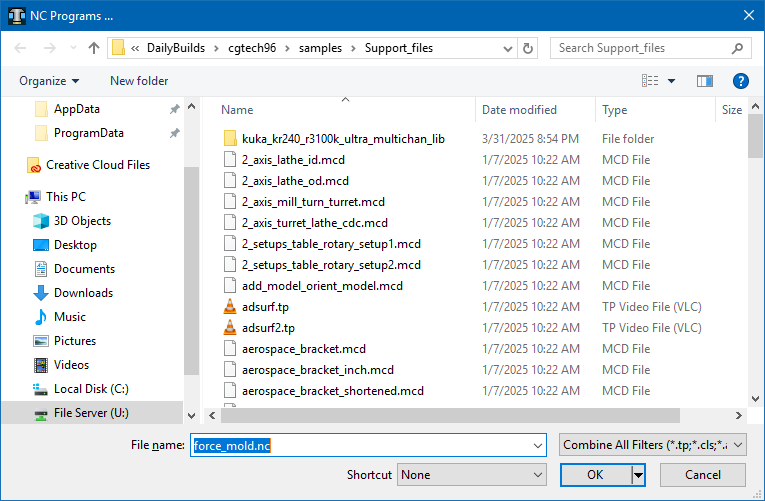
Most features on this window are standard file selection window features that enable you to navigate through directories, filter files, and type, or select, /path/filenames. A description of features specific to Vericut can be found in the Introduction to Vericut File Selection Windows section of Vericut Help.
You can select one, or more, files at the same time. To select multiple files, try these techniques:
Select multiple files in sequence — Click the first file in the sequence so that it becomes highlighted, then press and hold the <Shift> key while clicking the last file in the sequence. The first, last and all files between will become highlighted and can then be moved as a group.
Select additional individual files — Click the first file so that it becomes highlighted, then press and hold the <Control> key while selecting each additional file so that they become highlighted. All of the highlighted files can then be moved as a group.
With either method, selecting a file a second time, while holding down the <Control> key, un-selects the file.
The files are added to the Project Tree in the order that they appear in the NC Programs file selection window.
When the desired files are selected, click OK to add the file(s) to the appropriate place in the Project Tree.
Using the NC Programs File Selection Window
-
Select the folder in the folder tree on the left side of the window containing the NC program file(s) that you want to open. Use the
 (Up One Level) icon, located above the folder tree, to quickly move up one level in the folder tree structure.
You can also select the folder from the Shortcut pull-down list, located above the folder tree, if it is found there. -
Once you select the folder in the folder tree, the files in that folder are displayed in the center section of the file selection window. Use the Filter feature to specify the type of files that you want displayed.
-
Select one, or more, files that you want to add to the current Setup from those displayed in the center section of the file selection window so that they become highlighted.
Use the <Shift> key to select a range of files. Select the first file in the range, and then hold down thekey while selecting the last file in the range.
Press and hold the <Control> key while selecting multiple individual files. -
Click on the OK at the bottom of the window to add all of the files in the Current NC Program list to the Project Tree and close the file selection window.
- You can click on Cancel at the bottom of the window to close the file selection window without making any NC program file changes.
Add, Modify, or Delete NC Programs
NC program files are ASCII text files that contain data describing cutting tool positions, machine information, and other information required to operate NC machine tools.
To add an NC program file to the NC Programs branch:
-
To add an NC Program file, in the Project Tree click in the NC Programs branch to display the Configure NC Programs menu, and then click on Add NC Subroutine Files to display the NC Programs file selection window.
You can also right-click on the NC Programs branch and select Add NC Program Files in the menu that displays, or double-click on the NC Subroutines branch, to display the NC Programs file selection window. -
In the NC Programs file selection window that displays, select the NC program file(s) to be added, then click OK. If needed, refer to Using the NC Programs File Selection window section above.
The new NC program file name(s) are added to the NC Programs branch.
To replace an NC program file in the NC Programs branch with a different file:
- To replace an NC program file with another, in the Project Tree right-click on the NC program that is to be replaced and then select Delete from the menu that displays.
-
Click in the NC Programs branch to display the Configure NC Programs menu, and then click on Add NC Program Files to display the NC Programs file selection window.
You can also right-click on the NC Programs branch and select Add NC Program Files in the menu that displays, or double-click on the NC Subroutines branch, to display the NC Programs file selection window. -
In the NC Programs file selection window, type, or select the /path/filename of the replacement NC program file, and then click OK.
The replacement NC program file name is added to the NC Programs branch.
To delete an NC program file from the NC Programs branch:
To delete an NC program from the NC Programs branch, in the Project Tree right-click on the NC program that is to be deleted and then select Delete from the menu that displays. The NC program is removed from the NC Programs branch.
To delete all NC programs from the NC Programs branch, in the Project Tree right-click on the NC Programs branch and then select Delete All from the menu that displays. All subroutine are removed from the NC Programs branch.
Deleting NC program files from the Vericut configuration does not delete the files from your computer.
To edit an NC Program from within Vericut:
-
To edit an NC program, in the Project Tree right-click on the NC program to be edited and then select Edit from the menu that displays.
-
The contents of the NC program file will display in a text editor window. (see NC Program Editor in the Utilities tab section of Vericut Help for information about the text editor window). Edit the contents of the NC program file as necessary. When finished editing, select File tab > Save Project (or Save As) in the NC Program editor main menu to save your changes.
- Select Exit in the text editor main menu to close the text editor window.
Also see Advanced Control Options window: Subroutines tab and Add, Modify, or Delete Control Subroutines, in the Configure tab section of Vericut Help for information about "control" subroutines.
Also see Machine Settings window: Subroutines tab and Add, Modify, or Delete Machine Subroutines, in the Configure tab section of Vericut Help for information about "machine" subroutines.