Dimensions group
Location:
Tool Manager > X-Caliper tab > Dimensions group
X-Caliper tab > Dimensions group
The X-Caliper Dimensions group command buttons are used to control saving X-Caliper measurements as they are taken. These command buttons are used to generate and remove Dimension labels as needed. Once a label has been created, it will appear in the View window as a block of text with a plus sign (+) indicating where the label was created.
Display sub group
Display Labels — this feature is used to specify how X-Caliper measurements will be saved. Toggle this feature on (checked) to be able to display labels . By choosing an option in conjunction with the Information command button, labels of information can be saved. These labels can be moved around the View window by left-clicking and dragging the label to a new location. You can also press the <Delete> key on your keyboard to remove the last dimension label that was added.
 Remove All Dimensions — removes all labels that have been collected, regardless of whether they have been selected.
 Add Unattached Notes — Adds a floating note to be edited with whatever information you desire to input. To create a note, drag your mouse diagonally in a view to create the note text box. Type the desired text into the box and then resize or move the box around as desired. While still in edit mode, you can delete the note or switch between attached and unattached notes. Click outside of the box when you are finished to set the note.
 Add Attached Notes — Adds a note with a line pointing to a specific location where the note will be located. To create a note, drag your mouse diagonally in a view to create the note text box. Type the desired text into the box and then resize or move the box around as desired. While still in edit mode, you can delete the note or switch between attached and unattached notes. Click outside of the box when you are finished to set the note.
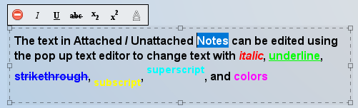
The text in Attached and Unattached notes can be edited with italic, underline, strikethrough, subscript, and superscript effects. Colors for individual notes and words can also be modified by highlighting text in a note with the Left Mouse Button. The pop up text editor appears above the text window with several options:
Text Display — To change the color for the labels feature, click on the  (Color Palette) icon to display the color palette window shown below.
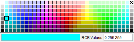
Click on a color in the color palette window, to specify the color for the label feature. The color palette window will close and the right side of the  (Color Palette) icon in the Dimensions group will update to reflect the selected color.
To close the color palette window without changing the color, click on the ![]() in the upper right corner of the color palette window.
in the upper right corner of the color palette window.
Additionally, there is a number field next to the color palette icon which can be used to specify the font size of the label.
 Extra Settings — this feature opens the Label Settings popup which enables you to control the information displayed by default for measurement labels. Changing settings in this window are effective for subsequent measurements. Settings are saved to your Preferences file. Label settings can also be altered by right-clicking the label in the view window.
Label Settings popup
| Standard Label Settings popup | Tool Manager Label Settings popup |
|---|---|
 |
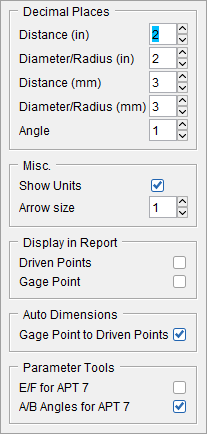 |
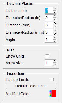
Decimal Places
The options in this sub group are used to set measurements to a specific decimal place by either clicking the up or down arrows to incrementally increase the places or else the number of places can be manually edited and typed into the number field. The following options are available to have their decimal places set: Distance, Diameter/Radius, and Angle.
Misc.
Show Units — toggle this option on (checked) to display the units being used.
Arrow size — use this option to increase or decrease the size of arrows in labels.
Inspection
This feature is exclusive to the standard Label Settings popup.
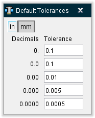
Display Limits — toggle this option on (checked) to display the default tolerances in the graphics area.
Default Tolerances — opens a pop up Default Tolerances window enabling you to set tolerance values up to 4 decimal places.
Modified Color — Use to specify the color that will display when modifications are made to the displayed dimension value is changed. Making changes to displayed dimensions is only available while creating Inspection dimensions and images under Annotated Images.
Display in Report
Driven Points — Toggle this option on to display the Driven Point symbols in the dimensioned images for reports.
Gage Points — Toggle this option on to display the Gage Point symbols in the dimensioned images for reports.
Auto Dimensions
Text Direction — Sets default text oriented in XZ or ZX direction depending on if the tool view is oriented vertically or horizontally.
Gage Point to Driven Points — Toggle option on to display dimension from the Gage Point to the Driven Point(s).
Parameter Tools
E/F for APT 7 — Toggle option on to display the E and F dimensions for APT 7 tools.
A/B Angles for APT 7 — Toggle option on to display the A and B angle dimensions for APT 7 tools.
Annotations sub group
 Show Annotation Plane — Select this option to display the annotation plane to place dimensions on. Dimension text and leaders will align flat to the selected plane by default when an annotation plane is active.
 Hide Annotation Plane — Select this option to remove the active annotation plane. Dimension text will align flat to screen when there is no annotation plane selected. Hidden Annotation Plane is the default until an annotation plane is selected.
 /
/ Text Aligned to 3D Plane/Text Flat to Screen — Toggle option to set how the dimension text is oriented when using an annotation plane. When an annotation plane is used, by default the dimension text will align to that selected annotation plane. Use Text Flat to Screen when using an annotation plane and text flat to screen is desired. Using Text Flat to Screen option allows text to be flat to screen but still have ability to move dimension and leaders along the selected annotation plane. Option will remain modal until user changes setting.
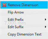
Annotations can be manipulated by left clicking on the text which generates the following popup menu:
-
Remove Note — clicking the red x deletes the measurement or annotation permanently.
-
Add Leader Line — creates a line that can be manually placed to point to any feature you wish.
-
Detach Note — removes any existing leader lines.
-
Edit Note — use this feature to alter existing text.
-
Copy Dimension Text — use this feature to save the current text for pasting later.
Text Aligned to 3D Plane/Text Flat to Screen — Toggle option to set how the dimension text is oriented when using an annotation plane. When an annotation plane is used, by default the dimension text will align to that selected annotation plane. Use Text Flat to Screen when using an annotation plane and text flat to screen is desired. Using Text Flat to Screen option allows text to be flat to screen but still have ability to move dimension and leaders along the selected annotation plane. Option will remain modal until user changes setting.
Angles sub group
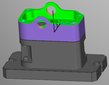
 Inside Angle — selecting this option means that the angle will be measure from the shortest distance between the two points selected (usually 90 degrees or less).
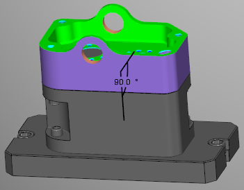
![]() Outside Angle — selecting this option means that the angle will be measure from the longest distance between the two points selected (usually over 90 degrees).
Outside Angle — selecting this option means that the angle will be measure from the longest distance between the two points selected (usually over 90 degrees).

![]() Supplement Angle — selecting this option will flip the measured angle by 180 degrees.
Supplement Angle — selecting this option will flip the measured angle by 180 degrees.
Circle sub group
 Radius — select this option to measure from the center of the circle to the end of the circle.
![]() Diameter — select this option to measure from one end of the circle to its opposite end.
Diameter — select this option to measure from one end of the circle to its opposite end.
 Center — select this option to find the mid point of the circle.
Reference and Finish sub group
 Set Datum Reference — Select this option when creating Inspection images in the Annotated Images window to define any surface as a datum for use in GD&T. This option is only available on the standard Dimensions group.
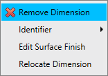
 Add Surface Finish — This option is only available on the standard Dimensions group. Select this option when creating Inspection images in the Annotated Images window to define any surface finish callouts necessary. Once a Surface Finish has generated, you can left-click on the symbol to see the following popup menu: