Optimization tab
The Optimization tab is displayed when a tool has been optimized. It displays info relevant to adjusting the optimizable features of the tool including stock material, various speed limits, and other advanced settings.
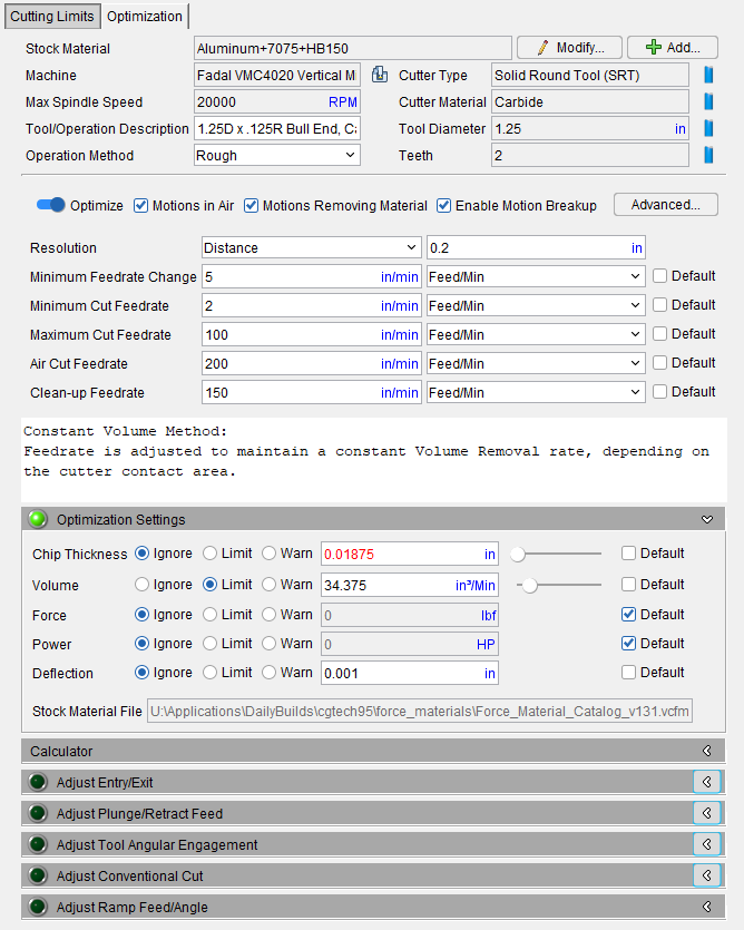
The Stock Material section shown above is identical to the Stock Material section shown in the Cutting Limits tab.
Optimize — Toggle this feature on (slider to the right) to optimize this tool. This enables the functionality of several features including the Optimization Settings tab below.
-
Motions in Air — Toggle on (checked) to optimize for Air Cuts.
-
Motions Removing Material — Toggle on (checked) to optimize for tool motions that take stock off of the model.
-
Enable Motion Breakup — Toggle on (checked) to view tool movements in smaller fragments rather than as a continuous whole.
Advanced Settings — opens the Advanced Optimization Settings window, enabling you to set various feedrate and tolerance values to help refine your optimization program.
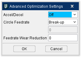
Accel/Decel — controls the acceleration and deceleration rates.
-
Off — Accel/Decel will be inactive.
-
Exact Stop — Assumes all axes must stop and be positioned exactly at the programmed location before the next block is processed. This option is recommended when sharp corners are required between motion blocks.
-
Continuous — Allows small errors in positioning in order to maintain a more constant velocity during corners or direction changes.
Circle Feedrate — controls when and how feed rates are optimized for circular motions (e.g. G02-3). Circle feed rate optimization produces a single optimized feed rate for the entire circular motion regardless of the active Modify Existing Cuts Only or Add More Cuts option.
-
Programmed — Uses the original programmed feed rate.
-
Fixed — Uses the feed rate in the corresponding data field.
-
Optimize — Calculates an optimized feed rate based on the maximum material removed throughout the circular motion.
-
Break-up — Breaks up NC blocks in to smaller distances in order to keep the chip thickness constant by adding feedrates to these added blocks. Note these changes do not adjust the trajectory of the cutting motion.
Radius Control — When toggled On, this adjusts the feedrate for circular motions. During circle motions, the program determines the maximum contact point away from the tool center line and adjusts the feed rate so the desired feed rate is achieved at that point. Radius Control is only available when Circle Feedrate is set to Optimize or Break-up.
📝 NOTE: If the effective cutting radius, R, is bigger than the circle radius, r, optimization adjusts (lowers) the feedrate by the factor r/R which is < 1. If R is less than r (r/R > 1), no adjustment is done (this will not increase the feedrate calculated based on the tool center).
NURBS Feedrate — Controls when and how to optimize NURBS motion feed rates (e.g. G06, G06.2). The active Modify Existing Cuts Only or Add More Cuts option does not affect feed rates calculated by this feature.
-
Programmed — Uses the original programmed feed rate.
-
One Feedrate — Calculates the most efficient feed rate for NURBS motions. The feed rate calculated for the most severe cutting condition used as the optimized feed rate.
-
Multi Feedrate — Calculates multiple feed rates for NURBS motions when cutting conditions warrant feed rate changes.
Feedrate Wear Reduction — Reduces the calculated feed rate based on the amount of material that has been removed. The value entered is the percentage of reduction to be applied after each cubic unit of material removed. Zero indicates no adjustment for wear.
Example: assume "Feedrate Wear Reduction=.2". The calculated feed rate is reduced .2% after each cubic unit of material has been removed. After five cubic units removed the calculated feed rate is reduced 1% (.2% x 5).
Clean-up Volume Tolerance — Cuts which remove less volume of material than this value will be consider to have not remove material at all. Feedrate optimization will treat the motion as just touching the material, meaning it will apply the Clean-up Feedrate value. Material removal parameters (Chip Thickness, Contact area, etc.) for the motion found in places like Status and Graphs will be zero.
The Clean-up Volume Tolerance can be useful when the optimized feedrates of a tool are often being assign to a material removal feedrate for superficial cuts that the user would prefer be assigned the Clean-up Feedrate value. It can also be useful as a filter to allow superficial material removal cuts to be interpreted by the optimization process instead as touching contact, resulting in more stable analysis in some cases.
The default value of 0 means this tolerance is not applied at all. Values of 0.00001 in^3 or 0.15 mm^3 are good places to start with if this tolerance does need to be used.
Spindle Speed — Spindle speed controls the rotations per minute (RPM) of optimized spindles. Toggle this feature on (button to the right), to activate this feature. Use the RPM slider beneath the toggle or the value field to the right of the slider to set the RPM for spindle speed.
Resolution — controls the frequency or "sampling distance" used to analyze each tool path motion. Recommended setting under normal circumstances is best to leave this setting as “Auto”.
For Milling operations this is calculated by:
10*(Cutting Resolution) found in Project, settings, Cutting Resolution.
For Turning operations:
Resolution is based on insert size. The value is 5% of the biggest insert size capped between 0.1 and 10 millimeters (or equivalent in inch).
Each feed rate controlled motion is partitioned into samples based on this distance. The samples are then analyzed during feed rate calculation. Toggle the Default checkbox on (checked) to have Vericut provide data for your tool automatically. Toggle off (unchecked) to enter your desired values manually.
Minimum Feedrate Change — specifies the minimum change from the current optimized feed rate that will cause new NC code blocks with optimized feed rates to be output. This feature controls the quantity of new blocks of code added and the tolerance to how tight the chip thickness is held constant. If there is a noticeable irregularity in the Force Graphs for chip thickness it may help to adjust this to a smaller value.
A small value causes more NC code blocks to be created with optimized with adjusted feed rates than when a larger value is used.
Default values are: Inch = 1 and Metric = 25.
Toggle the Default checkbox on (checked) to have Vericut provide data for your tool automatically. Toggle off (unchecked) to enter your desired values manually.
📝 NOTE: All feedrate measurements can be set to Feed/Min or Feed/Rev depending on which measurement you prefer.
Minimum Cut Feedrate — specifies the minimum optimized feed rates that can be output when removing material. Default values are: Inch = 1 and Metric = 25. Toggle the Default checkbox on (checked) to have Vericut provide data for your tool automatically. Toggle off (unchecked) to enter your desired values manually.
Maximum Cut Feedrate — specifies the maximum optimized feed rates that can be output when removing material. Default is 150% of Max Feed Rate. It's recommended to leave this as the default value unless there is a good reason not to. Toggle the Default checkbox on (checked) to have Vericut provide data for your tool automatically. Toggle off (unchecked) to enter your desired values manually.
📝 NOTE: the Minimum and Maximum Cut Feedrate can influence the optimized NC Program and graph due to not letting the feed resolve to the value needed to adjust for meeting the chip thickness target. This feedrate is material dependent and there may be an inclination to make this very low but doing so may restrict the optimization from setting the ideal feed for the small material entry (engagement) and exit. Example: when adaptive milling there is small crescent of material there needs to be a high feed to keep the chip thickness constant.
Air Cut Feedrate — Vericut detects when the cutting tool is not in contact with material and assigns this value as the Air Cut Feedrate. When the Default checkbox is cleared, this feature controls the feed rate used by all other optimization methods to optimize the air cuts. Default is 100% of Max Feed Rate. This feedrate can be set to % of Prog in addition to Feed/Min and Feed/Rev. Toggle the Default checkbox on (checked) to have Vericut provide data for your tool automatically. Toggle off (unchecked) to enter your desired values manually.
Clean-up Feedrate — feedrate used when the tool is adjacent to, but not removing material. This condition is commonly referred to as a "spring pass". Default is 50% of Max Feed Rate. This feedrate can be set to % of Prog in addition to Feed/Min and Feed/Rev. Toggle the Default checkbox on (checked) to have Vericut provide data for your tool automatically. Toggle off (unchecked) to enter your desired values manually.
Optimization Message Area — provides information about the selected optimization method and provides explanations when an adjust feature group is expanded.
Optimization Settings
This group presents settings based on the selected Optimization Method. A green light appears in the top left corner of this section when all required settings have been filled in satisfactorily. Use Calculator button expands the “Calculator” group to offer assistance to users with calculating feeds and speed related information.
You can select any combination of limits/warnings in the Optimization Settings listed below. Specify between Ignore, Limit, and Warn options then use the value fields to set values at which those options kick in. Toggle the Default checkbox on (checked) to have Vericut provide automatic values for each setting or toggle Default off (not checked) to input your preferred values manually.
📝 NOTE: Users are unable to enter values outside of set ranges; the value entered is reset to the limit and colored red. The corrective action for this is to visit SM tab and change range Min and/or Max value(s), then complete the change in Optimization Settings.
Chip Thickness — This is the primary consideration used to calculate optimized feedrates. When selected, optimizes cutting by flat, ball, and bull nose endmills based on maintaining a specified chip thickness. This method increases the feed rate when width of cut is less than 50% cutter diameter, or when depth of cut is less than the tool corner radius. Good for optimizing high speed machining and for semi-finishing and finishing operations using carbide cutting tools where the danger of "chip thinning" exists. It is especially effective for mold and die applications machining hard materials. Use the slider bar or enter the chip thickness in the data field to set the thickness.
Volume — When selected, optimizes based on a constant volume of material to be removed. This option is good for optimizing tools that encounter widely varying cutting conditions, such as hogging or roughing operations that cut at different cut depths and widths. Use the slider bar or enter the volume removal rate (cubic units) in the data field.
Force — When selected, optimizes based on Newtons exerted by a tool during tooling. This option is good for optimizing tools that are delicate or require great pressure to perform their function.
Power — When selected, optimizes based on how much energy the tool requires to be used. This option is good for reducing power requirements in energy intensive tool parts.
Deflection — When selected, optimizes based on avoiding bending or breaking tools as much as possible.
Stock Material File — displays the Stock Material File referenced during optimization. This feature is only available for Force related features. All cutters will have their Stock Material File auto-selected.
Calculator —
-
Axial Depth of Cut — depth of cut, used to prevent gouges.
-
Radial Width of Cut — width of cut, used to prevent unintended cuts.
-
Feedrate — Feed rate calculated from feed per tooth, spindle speed, and number of cutting teeth on the cutter.
-
Feed per Tooth — Thickness of material or "chip load" removed by each tooth on the cutter.
-
Chip Thickness — When selected, optimizes cutting by flat, ball, and bull nose endmills based on maintaining a specified chip thickness. This method increases the feed rate when width of cut is less than 50% cutter diameter, or when depth of cut is less than the tool corner radius. Good for optimizing high speed machining and for semi-finishing and finishing operations using carbide cutting tools where the danger of "chip thinning" exists. It is especially effective for mold and die applications machining hard materials. Use the slide bar or enter the chip thickness in the data field. If unknown, unselect all optimization methods and use the Cutting Condition sliders to calculate it.
-
Volume Removal Rate — When selected, optimizes based on a constant volume of material to be removed. This option is good for optimizing tools that encounter widely varying cutting conditions, such as hogging or roughing operations that cut at different cut depths and widths. Use the slide bar or enter the volume removal rate (cubic units) in the data field. If unknown, unselect all optimization methods and use the Cutting Condition sliders to calculate it.
-
Spindle Speed — When selected, outputs spindle speed values that support optimized feed rates. This value is also considered for Cutting Condition calculations (see above). Use the slide bar or enter the spindle speed (revolutions per minute) in the data field.
-
Surface Speed — When selected, outputs surface speed values that support optimized feed rates. This value is also considered for Cutting Condition calculations (see above). Use the slide bar or enter the spindle speed (revolutions per minute) in the data field.
-
Unit Power — Power that is required to remove one cubic unit of material per minute. The power specification differs, depending on the units set for the optimization record.
-
Spindle Power — Power that is required to remove material. The value entered differs depending on the active units for the optimization record:
Inch units => horsepower required to remove 1 cubic inch of material
Metric units => kilowatts required to remove 1 cubic centimeter of material per second -
Update Optimization Settings — Saves the current settings after you have manually changed them.
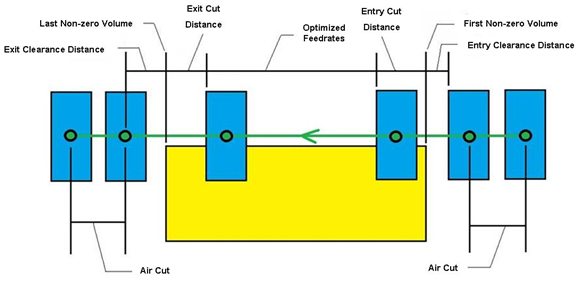
Adjust Entry/Exit —
This section can be used to initiate Vericut Force Optimization Hole Making by controlling the entry and exit of the cutting tool (normally a drill tool). This is very helpful for difficult to machine materials, angled surfaces, clevis parts, intersecting holes, manifolds, and multi axis drilling. All these hole making conditions are able to have the entry and exit optimized with Force Optimization.
Optimization is not always about going faster and run time savings. In hole making, optimization is about hole quality and tool life
The normal use for this feature would be to use the entry feedrate to slow down the drilling feed until the full diameter of the drill is engaged in the material, speed up to the programmed drilling feed until the tip of the tool starts to exit material, slow the feed down again as the tool exits the material preventing material blow out (burs).
Entry Feedrate — Use to specify when (by distance), and how (Feed/Min, Feed/Rev, % of Program, % of Calc), feed rates are calculated for entering material.
Exit Feedrate — Use to specify when, and how, feed rates are calculated for exiting material. Options are same as described for Entry Feedrate.
-
Off — Turns off Entry (or Exit) Feedrate calculation and application during optimization.
-
Feed/Minute — Uses the feed rate entered in the corresponding data field.
-
Feed/Rev — Similar to Feed/Minute but calculated by each revolution of the fool rather than time.
-
% of Prog. — Adjusts the programmed feed rate based on the percentage entered in the corresponding data field. 100% uses the programmed feed rate as is, 50% cuts feed rate in half, etc.
-
% of Calc. — Similar to % of Prog. except adjusts the calculated feed rate.
Clearance Distance — Use to specify the distance before entering material to start applying the specified Entry Feedrate or Exit Feedrate.
Cut Distance — Use to specify the distance to cut into material, using the Entry Feedrate or Exit Feedrate, before normal feed rate optimization resumes.
📝 NOTE: Adjust Turning Interrupted Cut works the same way as this section.
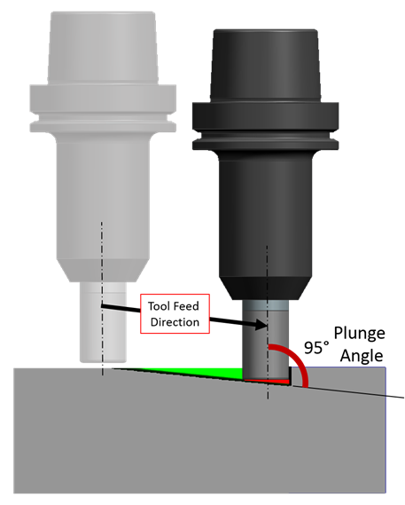
Adjust Plunge/Retract Feed —
Plunge Feedrate — Controls when and how feed rates are calculated for plunging along the tool axis into material.
-
Off — Disable plunge feed rate control.
-
Feed/Minute — Uses the feed rate entered in the corresponding data field.
-
% of Prog. — Adjusts programmed feed rates based on the percentage entered in the corresponding data field. 100% uses the programmed feed rate as is, 50% cuts the feed rate in half, etc.
📝 NOTE: Plunge Feedrate overrides Angle table feed rate for 90 degree cutting angle (plunge motion), or the Entry Feedrate for entry on plunge motions.
Retract Feedrate — Controls when and how the feed rates are calculated for retracting along the tool axis away from material.
-
Off — Disable retract feed rate control.
-
Feed/Minute — Uses the feed rate entered in the corresponding data field.
-
% of Prog. — Adjusts the programmed feed rate based on the percentage entered in the corresponding data field. 100% uses the programmed feed rate as is, 50% cuts feed rate in half, etc.
📝 NOTE: Retract Feedrate overrides Angle table feedrate for -90 degree cutting angle (retract motion).
Clearance Distance — Specifies the distance from material to instate the feed rate for plunging.
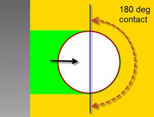
Adjust Tool Angular Engagement —
Adjust Feedrate for Milling Angular Engagement — Toggle on (checked) to activate the use of the following features:
-
Start Angle — The Angular Contact value at which to begin applying the adjustment. Cuts with angular contact values less than this will have no adjustment applied. The feedrate adjustment will then be applied in a linear manner from 0% reduction at this start angle to Max Feed Drop % at an angular contact value of 180° or greater. Range of input: [0°, 180°].
-
Max Feed Drop % — The maximum feedrate drop percentage applied. Range of input: [0, 100].
📝 NOTE: This adjustment is applied to all motions and all material removal, not just a simplified concept of horizontal slotting scenarios. As explained in Angular Contact[link], many material removal motions (e.g., downward ramping) will produce angular contact values >= 180°. As described above, these motions will have Max Feed Drop % applied.
 |
 |
|---|---|
Adjust Conventional Cut —
Adjust Feedrate for Conventional Milling Cut — Non-Climb, or "Conventional", cutting occurs when the cutter tooth enters material close to parallel to the direction of motion. See the following diagram:
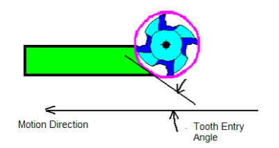
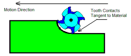
The cutting condition worsens as the tooth entry angle decreases. When the tooth entry angle is near zero the cutting edge contacts material parallel to the direction of motion and requires excessive force to push the edge into material. The tooth finally enters material when pressure between the cutter and material increases and the tooth rotates past the tangent contact.
The picture below shows the worst condition.
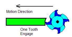
Adjust Feedrate for Thin Radial Width Cut — A thin radial width cut, typically only has one tooth engaged in material. When the width of material becomes so small that only one tooth of the cutter is engaged, the tool is no longer well supported and an otherwise reasonable feed rate becomes too aggressive. As the spindle spins the tool transitions between a tooth engaged and cutting, and no tooth engaged, causing the tooth to "bang" into material each time it enters. This "banging" causes premature cutting edge breakdown and reduces tool life.
Determining the number of teeth engaged depends on the number of teeth in the cutter, the material contact axial depth, the width and location of the contact, and the flute helix angle.
Adjust Feedrate for Side-Loaded Cut — A side-loaded cut, is a condition where material is exclusively on the "climb" side of the cutter
When the tool is cutting with all material on the right of the tool center (for a clockwise rotating spindle), the cutting pressure forces the tool to deflect in the opposite direction. The deflection seriously affects cutting performance, increases cutting forces, and causes premature edge breakdown.
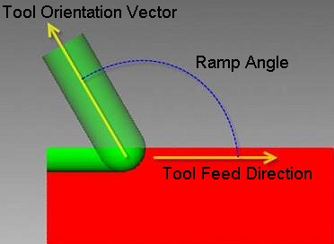
Adjust Ramp Feed/Angle —
Example of downward ramp cutting:
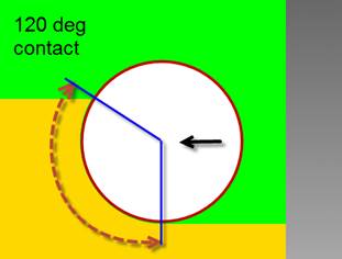
Vericut Force applies Ramp Feed Adjustment as a percentage of the optimized feedrate when the tool's ramp angle is greater than the specified start angle. Ramp angle is measured from the tool's feed direction. The angle when the tool is at a perpendicular position to the feed direction is 90 degrees.
The example below shows the tool at an approximate ramp angle of 120 degrees.
None — (Default) No adjustment for feedrates on ramping motions.
Adjust by Ramp Feed Drop — activates Start Angle, End Angle and Max Feed Drop % fields and enables data entry- same functionality as existing Force features. Default values as shown above.
Adjust by Ramp Angle — activates Ramp Angle table fields and enables data entry- same functionality as existing optimization features.
Start Angle — Use the text field to enter the starting angle in degrees. The Start Angle is the angle at which this feature starts to determine the angle of contact and reduces the feed rate as the engagement increases up to the reduction limit specified.
End Angle — The ramp angle (in degrees) to apply at which the maximum reduction in feedrate is applied, as specified by the Max Feed Drop % (described below).
Max Feed Drop % — The maximum feedrate drop percentage desired for ramp angle adjustment. The adjustment varies as the ramp angle changes between the ramping start and end angles.
💡 Tip: To have the Max Feed Drop % applied fully to all ramping motions, enter "90" degrees for Start Angle and End Angle values.
Angle table — Table of cut angles and corresponding % feed rate adjustments to apply when the tool ramps into material. Values can be entered or supplied via dragging the control points on the graph. Add after, or delete table entries via right-clicking on them and choosing the appropriate option (or use the Add / Delete buttons below the table). Cuts at angles less than the minimum listed in the table receive the adjustment specified for the minimum angle. Similarly, when the maximum specified cut angle is exceeded, the adjustment specified for the maximum angle is used.
Angle column — Lists up to five cut angles (in descending order) that describe the range of expected cut angles to adjust. Values can be from -90 to 90, where "0" represents horizontal milling, "90" represents plunge motion along the tool axis, and "-90" represents retract motion.
Feedrate column — Lists % feed rate adjustments to apply to calculated feed rates when ramping in material at the corresponding angle. 100% uses the calculated feed rate as is, 50% cuts feed rate in half, etc.