Configure Models Branch menu
Location: Project Tree > Models branch (Configure “on”)
The following Configure menu displays when a Models Branch is highlighted in the Project Tree.
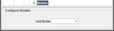
The Add Model feature provides the same functionality described in the Configure Component menu, Common Features section.
Configure Model menu
Locations:
Project Tree > Model (Configure “on”)
Project Tree > Cut Stock (Configure “on”)
The Configure Model menu is used to define the models that represent the solid objects used in the simulation.
The features that appear on the Model tab will vary depending on the Model Type. These differences will be described in the following sections.
Model tab — Features on the Model tab are used to add and modify models that are attached to components to provide 3-D shape. This tab is only available when a model is highlighted.
Translate tab — Features on this tab translate the selected object via indicating "from" and "to" points to move the object.
Rotate tab — Features on the Rotate tab rotate the selected object about a rotation center point.
Assemble tab — Features on the Assemble tab move the object by assembling (mating or aligning) it with other objects.
Matrix tab — Features on the Matrix tab enable you to move a selected component/model from one coordinate system to another.
Csys tab — Features on the Csys tab enable you to move a selected component/model from one coordinate system to another.
Mirror tab — Features on the Mirror tab enable you to mirror a model about a specified axis (plane). This tab is only available when a model is highlighted.
Add Model — Selecting Model File displays the Open file selection window enabling you to specify the model file to add to the Project Tree. Once the model file is added, the to the Project Tree, the Configure Model menu displays with Type set to “Model File” model’s position.
See Model Type: Model File in the Configure Model menu, Model tab section of Vericut Help for information on the various model file types that can be used in Vericut.
Configure Model menu, Model tab
The features on the Model tab are used to add and modify models that are attached to components to provide 3-D shape. The models can be simple parametric shapes, or refer to external model files.
The following features are common for all Model Types:
Type — Use to specify the type of model being defined. The active choice determines the features that will appear on the Model tab.
| Model type: | Appears in the Project Tree: |
|---|---|
| Block |  |
| Cone |  |
| Cylinder |  |
| Model File | 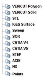 |
Visible — Toggles "on" (checked) or "off" to indicate whether or not the model should be displayed in the Vericut graphics area.
When toggled “on”, the model icon will indicate the visibility status of the model. For example, 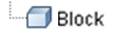 in the Project Tree indicates that the model will be "visible" in the Vericut graphics area.
  in the Project Tree indicates that the model is "not visible" and will not be displayed in the Vericut graphics area.
📝 NOTE: This feature is not available when a Cut Stock is highlighted.
Appearance — Use this feature to specify a color for the model. The right side of the  (Color Palette) icon shows the current color for the model. To change the color for the model, click on the (Color Palette) icon to display the Appearance window shown below.
Appearance window
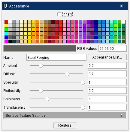
Click on a color in the color palette window to specify the color for the model. The color palette will close and the right side of the  (Color Palette) icon in the Configure Model menu: Model tab will update to reflect the selected color.
Inherit — Toggle this feature on (Checked) to apply the selected color permanently.
RGB Values — This text field lists the values of any selected color. They can also be manually edited to select a specific color.
Name — Use this text field to name the color to make it easier to find in the Appearance List.
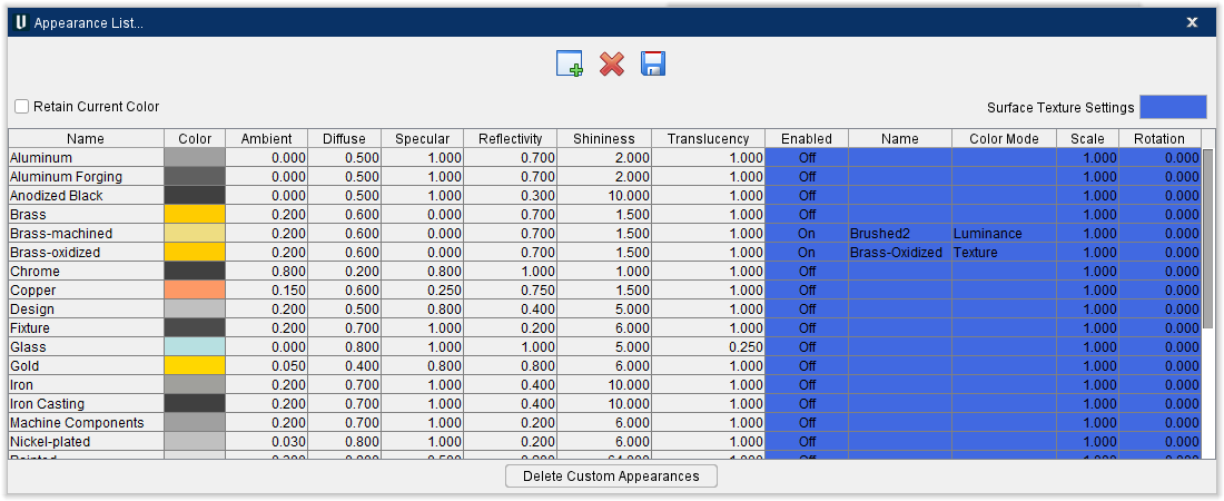
Appearance List — Opens the Appearance List window which lists several colors along with their values.
-
Add — Adds a new row to the Appearance List to be edited.
-
Delete — Deletes any selected rows.
-
Save — Saves the customized Appearance List as materialappearance.txt.
-
Retain Current Color — Toggle this feature on (Checked) to apply the selected color permanently.
-
Delete Custom Appearances — Resets the Appearance List to default settings and closes the window.
To close the Appearance List window without changing the color, click on the in the upper right corner or select Cancel. To accept the color change, select OK.
Several slider bars are listed here to give you greater control over the appearance than merely selecting colors from a list. These features can be altered either with the slider or with the text field next to the sliders.
Ambient — General intensity of lighting on the model, independent of orientation. Higher values result in brighter models. Slide the slider all the way to the right to make the model appear brighter. This feature also affects the Diffuse feature.
Diffuse — Intensity of lighting on the model based on the orientation of local surface normal relative to light sources. Higher values result in brighter models. Slide the slider all the way to the right to make the model appear more reflective and brighter. This feature also affects the Ambient feature.
Specular — Intensity of specular highlights on the model. Heavily affected by the shininess value. Higher values result in brighter highlights. Slide the slider all the way to the right to make the model's "bright spot" appear more pronounced. This feature also affects the Shininess feature.
Shininess — Controls the spread of specular and reflective highlights. A low value will result in the highlights spreading out over the entire model while higher values will concentrate the highlights. Slide the slider all the way to the right to make the model appear duller and slide the slider all the way to the left to maximize shine. This feature also affects the Specular feature.
Reflectivity — This feature controls how much light is reflected off the model. Slide the slider all the way to the right to maximize reflectivity.
Translucency — Controls how translucent the model is. Low values are highly translucent, while a value of one is opaque. This translucency setting belongs to the model representation and is independent of the translucency option set at the component and controlled in View Attributes. Slide the slider all the way to the left to make the piece almost completely invisible.
Restore — Click this button to undo any changes that have been made in this window.
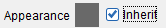
Models connected to the component have the option to "Inherit" or override the component's defined color. Then the Inherit option is toggled “on” (checked), the model will inherit the color from the component that it is attached to. In this case the Appearance feature will display the color that will be inherited as shown in the picture below.
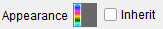
When the Inherit feature is toggled “off” (not checked), the (Color Palette) icon will be displayed enabling you to specify a color for the model as shown in the picture below.
Has Open Surface — Open surfaces are meshes that have holes in them. Toggle this feature on (checked) if your model has an open surface which will allow the model to render correctly.
Edge Angle — This feature enables you to specify the angle that determines when Vericut is to create an “edge”.
The other features that are available on the Model tab will vary depending on the Model Type. Each of the variations is described in the sections that follow.
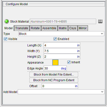
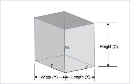
Model Type: Block
The following picture shows the Model tab that applies to Block models.
Model tab — Features on the Model tab are used to add and modify models that are attached to components to provide 3-D shape. The models can be simple parametric shapes, or refer to external model files.
Features: Type, Visible, and Color are common to all model types and are described in detail in the Configure Model menu: Model tab section.
The following features are specific to Block models.
Length (X) — Use the text field to specify the length (along the X-axis of the Model coordinate system) dimension of the block.
Width (Y) — Use the text field to specify the width (along the Y-axis of the Model coordinate system) dimension of the block.
Height (Z) — Use the text field to specify the height (along the Z-axis of the Model coordinate system) dimension of the block.
Block from Model File Extent — This feature enables you to select a model file representing the design model and have Vericut create a stock block enclosing the selected model. Selecting Block from Model File Extent displays the Block from Model File Extent file selection window enabling you to select the model file. Use the Units pull-down to specify the units (Inch or Millimeter) to be used.
Block from NC Program Extent — When defining a Block type model, this feature automatically defines and locates a stock block based on tool positions in the current NC program file(s). Rapid and APT-CLS "FROM" tool positions are ignored during this calculation. The block size and location guarantee that the NC program will cut the block.
Offset — Use the Offset text field to specify the offset to be applied to the block created using Block from Model File Extent or Block from NC Program Extent (see above). The offset is applied to all dimensions.
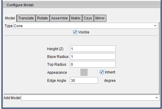
Model Type: Cone
The following picture shows the Model tab that applies to Cone models.
Model tab — Features on the Model tab are used to add and modify models that are attached to components to provide 3-D shape. The models can be simple parametric shapes, or refer to external model files.
Features: Type, Visible, and Color are common to all model types and are described in detail in the Configure Model menu: Model tab section.
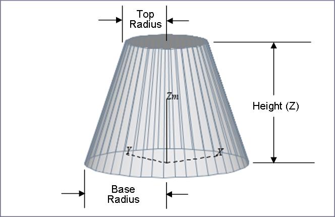
The following features are specific to Cone models.
Height (Z) — Use the text field to specify the height (along the Z-axis of the Model coordinate system) dimension of the cone.
Base Radius — Use the text field to specify the radius dimension at the base of the cone.
Top Radius — Use the text field to specify the radius dimension at the top of the cone.
Model Type: Cylinder
The following picture shows the Model tab that applies to Cylinder models.
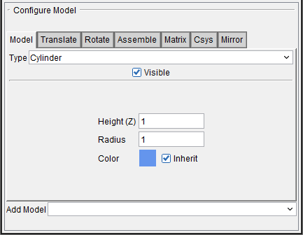
Model tab — Features on the Model tab are used to add and modify models that are attached to components to provide 3-D shape. The models can be simple parametric shapes, or refer to external model files.
Features: Type, Visible, and Color are common to all model types and are described in detail in the Configure Model menu: Model tab section.
The following features are specific to Cylinder models.
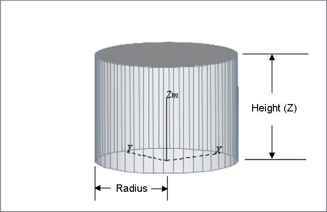
Height (Z) — Use the text field to specify the height (along the Z-axis of the Model coordinate system) dimension of the cylinder.
*Radius — *Use the text field to specify the radius dimension of the cylinder.
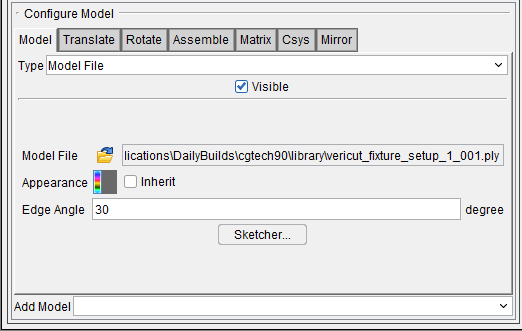
Model Type: Model File
The following picture shows the Model tab that applies to Model File (STL, Vericut Polygon, Vericut Solid, Sweep, SOR, IGES, CATIA V4, CATIA V5, STEP, ACIS, NX) models.

Model tab — Features on the Model tab are used to add and modify models that are attached to components to provide 3-D shape. The models can be simple parametric shapes, or refer to external model files.
Features: Type, Visible, and Color are common to all model types and are described in detail in the Configure Model menu: Model tab section.
The following features are specific to Model File models.
Model File — Use the Model File feature to specify the file containing the model data. Click on the  (Open File) icon and use the Open file selection window that displays to select the model file.
The following model file formats are supported in Vericut:
-
Vericut Polygon — A Vericut Polygon file, or "Polygon file" for short, is an ASCII text file that describes virtually any shape open surface or enclosed shape. Typical file extensions: design- .dsn, fixture- .fix, stock- .stk, any- .ply
See Vericut Polygon File in the Getting Started section of Vericut Help for additional information. -
Vericut Solid — A Vericut Solid file is a binary file containing data representing a cut stock model. Typical File extension: .vct
See Save or Load a Vericut Solid (.vct file) section of Vericut Help for additional information.
Also see Vericut Solid File section of Vericut Help for additional information. -
STL — A Stereolithography model file, also known as an "STL" or "SLA" file, is an ASCII text or binary file which describes virtually any surfaced or solid model shape. Typical file extension: .stl
See Stereolithography (STL) Model File section of Vericut Help for additional information. -
IGES — An IGES (Initial Graphics Exchange Specification) model file, also known as an "IGES file", is an ASCII text file which describes virtually anything that can be modeled in a CAD system. Typical file extension: .igs
See IGES Model File section of Vericut Help for additional information. -
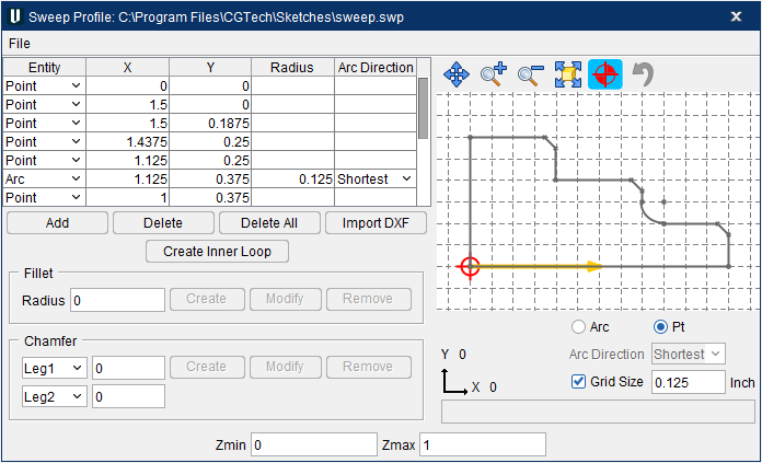
Sweep — A Vericut Linear-sweep file, or "Linear-sweep file" for short, is an ASCII text file that describes an extruded shape. A 2-D profile is defined in the XY plane, and then swept (extruded) along the model's Z axis. Typical file extension: .swp
See Vericut Linear Sweep File in the Getting Started section of Vericut Help for additional information. -
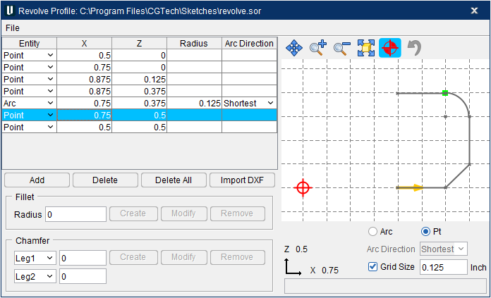
SOR — A Vericut Solid-of-revolution file, or "Solid-of-revolution file" for short, is an ASCII text file that describes a revolved shape. A 2-D profile is defined in the ZX plane, and then revolved around the model's Z axis. Typical file extension: .sor
See Vericut Solid-of-Revolution File section of Vericut Help for additional information. -
CATIA V4 — A CATIA V4 model file is a binary file created using CATIA V4 Release 2.5. This is the final release of CATIA V4. Typical file extension: .model
Use of these files in Vericut requires a CATIA V4 Model Interface license, and the installation of the CAD Model Interface files (aka the \"Spatial Technologies\" libraries). See the Vericut website for additional information. -
CATIA V5 — A CATIA V5 file is a binary file created using CATIA V5 (requires CATIA V5). Typical file extension: .CATPart
Use of these files in Vericut requires a CATIA V5 Model Interface license, and the installation of the CAD Model Interface files (aka the \"Spatial Technologies\" libraries). See the Vericut website for additional information. -
STEP — A STEP model file is a 3D model file formatted in STEP (Standard for the Exchange of Product Data), an ISO standard exchange format; used for representing three-dimensional data in a format that can be recognized by multiple programs. A STEP model file is an ASCII text file.
See the Vericut website for additional information. -
ACIS — An ACIS model file is model file created using the 3D ACIS Modeler (ACIS) owned by Spatial Corporation (formerly Spatial Technology). An ACIS model file is an ASCII text file. Typical file extension: .sat
Use of these files in Vericut requires an ACIS Model Interface license, and the installation of the CAD Model Interface files (aka the \"Spatial Technologies\" libraries).
See the Vericut website for additional information on the ACIS Model Interface. -
NX — An NX model file is a binary file created using Siemens NX CAD system (requires NX6, NX7, NX7.5, NX8, or NX8.5 with Vericut 7.3 or later). An NX part file can be opened directly in Vericut if the following requirements are met.
-
NX6, NX7, NX7.5, NX8, or NX8.5 must be installed on the computer that's running Vericut.
- An NX license must be available.
- The following environment variables need to be set in Vericut's environment:
UGII_BASE_DIR
UGII_BASE_DIR is setup by an NX installation in the system environment space and typically points to the place where NX is installed, for example C:/Program Files/UGS/NX 6.0/.
UGII_ROOT_DIR
UGII_ROOT_DIR is setup by an NX installation in the system environment space and typically points to the location of the NX executable files, for example C:/Program Files/UGS/NX 6.0/UGII/.
Also, UGII_ROOT_DIR must be set in the execution path (the "path" environment variable).
Since a NX part file can contain multiple models, a pop-up window displays with a list of models contained in the NX part file. If a model was named in NX, it is listed by name in the window. If the model was not named in NX, it is displayed in the list as "Unnamed" followed by a number as shown in the picture below.
You can select multiple models that are in a group by selecting the first model in the group and the hold down the Shift key and select the last model in the group. You can select multiple individual models by selecting the models while holding down the Control (Ctrl) key.
See the Vericut website for additional information on the NX Model Interface.
Also see Installing the Model Interface Modules in the Installing Vericut Products section of the Vericut Help Library.
- Design Points — An ASCII text file, also known as an "inspection point file" that contains point locations used to inspect the Vericut model when performing an AUTO-DIFF Point comparison operation. Typical file extension: .pts
See Design Points File section of Vericut Help for additional information.
Sketcher — Displays the Profile Sketcher window enabling you to edit or create a "Sweep solid (.swp)" or "Revolve (.sor)" model file.
Selecting Sketcher with a Model Type: SOR highlighted in the Project Tree opens the Profile Sketcher window in "Revolve" mode.
Selecting Sketcher with a Model Type: Sweep highlighted in the Project Tree opens the Profile Sketcher window in "Sweep" mode.
Selecting Sketcher with any other Model Type highlighted in the Project Tree displays the Profile Type window enabling you to specify whether you want to open the Profile Sketcher window in “Revolve” mode or “Sweep” mode.
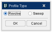
Select the profile type (Revolve or Sweep), then OK to display the Profile Sketcher window in the selected mode.
Use the Profile Sketcher window to create a new "Sweep solid (.swp)" or "Revolve solid (.sor)" model file.
Cancel dismisses the Profile Type window without opening the Profile Sketcher window.
Open window for Models
Locations:
Project Tree > Configure Models branch menu
Project Tree > Configure Model menu
Project Tree > Models Branch Right Mouse Shortcut Menu > Add Model > Model File
Project Tree > Model Right Mouse Shortcut Menu > Add Model > Model File
The Open file selection window for models enables you to add one or more model files (ref. Vericut File Descriptions in the Getting Started section of Vericut Help for information about supported model types.).
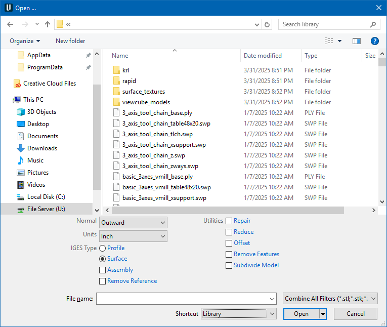
Most features on this window are standard file selection window features that enable you to navigate through directories, filter files, and type, or select, /path/filenames. A description of features specific to Vericut can be found in the Introduction to Vericut File Selection Windows section of Vericut Help.
The file selection window for models has some additional features on the right side of the file selection window. Those features are described below.
Normals — This feature applies to STL file models only and indicates the direction in which surface normals defined in the STL data point, relative to the model. Select Inward, Outward, or *omputed *(let Vericut determine the direction of the surface normals).
Units — Select between Inch or Millimeter for the model file.
IGES Type — Use to specify whether the IGES file contains Profile, or Surface, data.
Assembly — Use this feature to specify whether you want a STEP, NX, PRO/E, SOLIDWORKS, CATIA V5, 3DXML, or CGR model loaded as individual components or as an assembly.
When toggled "off" (unchecked), the file is loaded as a single model. When toggled "on" (checked) the file is loaded as individual components. A model will be created for each component found in the file.
Remove Reference — When toggled "on" (checked), an ASCII Vericut Polygon File will be created for CATIA V5, NX and STEP files. The reference to the CATIA V5, NX or STEP file will be severed and the model is referenced by the newly created ASCII Vericut Polygon File.
Utilities
Repair — When toggled on (checked), this feature analyzes and repairs inconsistent surface displays to create the best possible model. This feature is automatically applied when Offset or Reduce are also toggled on (checked). Models that are repaired are saved with the extension: mu_repaired.ply.
Reduce — When toggled on (checked), this feature uses the specified deviation tolerance to create a new coarser model using triangle reduction, but typically has less accuracy especially in areas with curvature. The value specifies the maximum deviation that the new model can deviate (+ or -) from the original model. Reduced models are saved with the extension: …mu_reduce=[#DeviationTolerance].ply. When toggled off (not checked) no reduction is performed.
Example 1: A model reduced by 5 would produce the extension: mu_reduce=5.ply.
Example 2: A model reduced by 0.1 would produce the extension: mu_reduce=0_1.ply.
Offset — When toggled on (checked), this feature uses the specified value to offset model surfaces for creating a new larger (or smaller) model. A positive value creates a new larger model, while a negative value creates a smaller model. Offset models are saved with the extension:…mu_offset=[#OffsetAmount].ply.
-
Positive offset value — offsets model surfaces in a "growth" direction to create a larger file than the original.
-
Negative offset value — offsets model surfaces in a "shrink" direction to create a larger smaller than the original.
-
Example 1: A model offset by 5 would produce the extension: mu_offset=5.ply.
-
Example 2: A model offset by 0.1 would produce the extension: mu_offset=0_1.ply.
Remove Features — When toggled on (checked), enables you to specify tolerance units to remove features that intrude inward or protrude outward from the surface of the model. This feature works best with good quality prismatic parts and may not work well with parts containing freeform surfaces.
-
Inward — any features that intrude inward from the surface whose diameter is less than the diameter tolerance specified in this field will be removed.
-
Outward — any features that protrude outward from the surface whose diameter is less than the diameter tolerance specified in this field will be removed.
Subdivide Model — When toggled on (checked), the tolerance field can be used to specify maximum distance from any point on the surface of the model to the convex hull of the model. This field is specified in whatever units where originally used for the incoming model and not in the units the user may have specified for the model afterward. The model will be subdivided continuously until each submodel meets the specified tolerance.
Utilities features can be used simultaneously. For example, a model can both reduced by 1 and offset by 5 producing the extension: mu_reduce=1_offset=5.ply.
Profile Sketcher window
Locations:
Project Tree > Configure Component menu > Add Model > Create Revolve
Project Tree > Configure Component menu > Add Model > Create Sweep
Project Tree > Configure Model menu: Model tab (Model File) > Sketcher
Project Tree > Configure Model menu > Add Model > Create Revolve
Project Tree > Configure Model menu > Add Model > Create Sweep
| Project tab > Tools > Add(Modify) Cutter >Tool Component tab: | |
|---|---|
| Project tab > Tools > Add(Modify) Insert >Tool Component tab: | |
| Project tab > Tools > Add(Modify) Holder >Tool Component tab: | |
| Project tab > Tools > Add(Modify) Holder >Tool Component tab: |
The Profile Sketcher provides an easy graphical means of describing a profile in 2-D drawing space. Profiles are sketched by connecting a series of lines and arc segments. You can select points, enter point/arc data into the Profile entity list, or pick then edit entity values in the list. You can also import the 2-D geometry from a DXF file. The profile displayed in the sketcher window is constantly updated regardless of how you supply profile entity data, making it easy to see what you've defined.
Revolve Profile mode, where an "open" 2D profile is rotated about the Z-axis to create a solid model or cutter/holder.
or in Sweep Profile mode, where a "closed" 2-D profile is "swept" a specified distance along the Z-axis to create a solid model or a cutter insert/holder.
The options available in the Profile sketcher will vary slightly depending on whether it was accessed from one of the Model menu windows or from Tool Manager. Most of the features are common regardless of where the window was accessed from and have identical functionality. Those features that are specific to a particular function are located at the bottom of the window are described in the Special Features section below.
Common Features
Entity list — Lists the point/arc entities that define the profile. The list is created by graphical selection, or by pressing Add to add entities to the list. Existing data can be edited directly in the Entity list.
Add — Adds a single entity to the Entity list. Once added, the entity type (Point or Arc) can be changed, or data values edited.
Delete — Deletes the highlighted entity from the Entity list.
Delete All — Deletes all entities in the Entity list.
Import DXF — Opens the DXF Geometry window enabling you import two dimensional tool geometry from files which comply with a de facto CAD system standard, the Data eXchange Format (DXF) to add (or modify) individual cutter (or holder) components in existing tool records.
Fillet
Radius — Use this text field to specify the radius of the fillet to be created or modified. Use with Create and Modify described below.
Create — Use to create a fillet at the selected point. Use Radius described above, to specify the size of the fillet.
Modify — Use to modify a fillet. Select the fillet in the Entity List and then set Radius to the new value. Finally, click on Modify to update the fillet.
Remove — Use to remove the highlighted fillet from the Entity List.
Chamfer
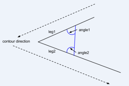
A chamfer can be defined at a corner between two line segments. To create a chamfer you need to select a corner point, and then define two length parameters: (leg1 + leg2), or a length and an angle parameter, e.g. (leg1 + angle2). See the picture on the following page.
If you specify two angle elements the chamfer will not be created, since two angles are not enough information to define a chamfer. A message will be displayed in the lower right corner of the Profile Sketcher window.
When a chamfer is defined it can be modified by selecting it and changing the type and/or the value of its defining parameters.
For example, if you defined a chamfer by leg1 = 1, angle1 = 30, you can now modify it by specifying angle1 = 35, leg2 = 1.2. While you are working on your sketch, each chamfer construction method will be remembered, and can be modified. However when you save the resulting profile all chamfers will be save just as line segments, the construction details forgotten.
Entity 1 — Select one of the following entities (Leg1, Angle2, Angle1) from the pull-down list and then enter the value (distance or angle) for the selected entity in the in the text field next to the selected entity.
Entity 2 — Select one of the following entities (Leg2, Angle1, Angle2) from the pull-down list and then enter the value (distance or angle) for the selected entity in the in the text field next to the selected entity.
Create — Use to create a chamfer using the information supplied for Entity1 and Entity2 described above. Select Entity1 from the pull-down list and then enter the value in the text field.
Select Entity2 from the pull-down list and then enter the value in the text field. Finally, click on Create to create the chamfer.
Modify — Use to modify a chamfer. Select the chamfer in the Entity List and then set the new entity type and/or values. Finally, click on Modify to update the chamfer.
Remove — Use to remove the highlighted chamfer from the Entity List.
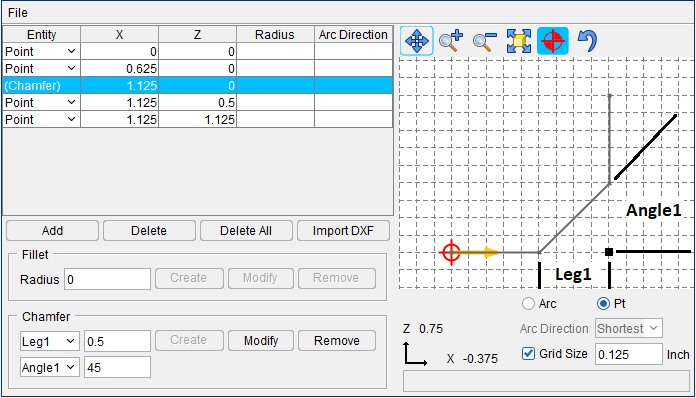
Example 1 – Create a 45 degree chamfer using a leg and an angle
- Set Entity 1 = Leg1 with a value of 0.5.
- Set Entity 2 = Angle 1 with a value of 45.
- In the Sketcher Entity List, select the intersection point of the 2 lines where you want the chamfer.
- Select Create to create the chamfer. See the diagram below.
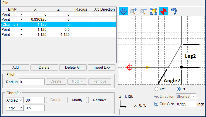
Example 2 – Create a 30 degree chamfer using a leg and an angle
- Set Entity 1 = Leg2 with a value of 0.5.
- Set Entity 2 = Angle2 with a value of 30.
- In the Sketcher Entity List, select the intersection point of the 2 lines where you want the chamfer.
- Select Create to create the chamfer. See the diagram below.
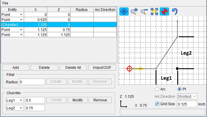
Example 3 – Create a chamfer using 2 legs
- Set Entity 1 = Leg1 with a value of 0.5.
- Set Entity 2 = Leg2 with a value of 0.75.
- In the Sketcher Entity List, select the intersection point of the 2 lines where you want the chamfer.
- Select Create to create the chamfer. See the diagram below.
↘️ Shortcut: Clicking with the right mouse button in the Sketcher window (Revolve Profile or Sweep Profile) displays the following shortcut menu:
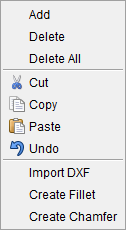
Most of these features provide the same functionality as those described above under Common Features.
The Create Inner Loop feature is only available in the Sweep Profile window and is described below in the Special Features section.
Sketcher window — Displays the current defined tool profile (blue line), based on the entity list. The profile in the window is constantly updated to reflect current list data. The following symbols may be seen in the sketcher window:
![]() Tool origin — The tool origin is assumed by Vericut to be the control point, or driven point, on the tool. Typically, tool profiles are sketched relative to the tool origin to provide proper cutting by the tool. However, the tool origin can be relocated at any time via dragging the origin point. Tool origin display is controlled by the Origin
Tool origin — The tool origin is assumed by Vericut to be the control point, or driven point, on the tool. Typically, tool profiles are sketched relative to the tool origin to provide proper cutting by the tool. However, the tool origin can be relocated at any time via dragging the origin point. Tool origin display is controlled by the Origin ![]() feature on the sketcher Toolbar (see below).
feature on the sketcher Toolbar (see below).
![]() (blue dot) Entity point — This symbol indicates a point on the profile or an arc center point. You can change the profile shape by dragging entity points to different locations. The corresponding entity in the list is automatically updated.
(blue dot) Entity point — This symbol indicates a point on the profile or an arc center point. You can change the profile shape by dragging entity points to different locations. The corresponding entity in the list is automatically updated.
 (green dot) Selected entity point — This symbol indicates the entity selected for editing. The corresponding entity in the list is also highlighted for editing.
📝 NOTE: Selecting a line segment in the Sketcher window selects both end points for editing. Drag the line segment to the desired location and both end points are automatically updated in the Sketcher window as well as in the Profile Entity List.
 (red dot) Target selection point — This symbol follows the mouse and is the target for graphical selection. Values displayed with the Sketcher axes below the sketcher window reflect the target selection point location.
Close Profile — When accessed from Tool Manager, this button appears. It is used to connect the X axis point to the Y axis point in order to fully simulate the 3D geometry of the profile in certain cases.
Sketcher axes — Axes that depict the coordinate system in which the tool profile is being constructed. Values displayed with the axes reflect the target selection point location, relative to the tool origin.

![]() (Arrow) — The arrow on the profile indicates the direction.
(Arrow) — The arrow on the profile indicates the direction.
Arc / Pt — Controls the profile entity type being defined via graphical selection.
Arc Direction — Controls the direction of an Arc being defined via graphical selection.
Grid Size — When selected, displays a grid in the sketcher window. When a grid is displayed, target and selected points snap to the nearest grid line intersection. Grid spacing is specified in the data field located right of the Grid Size label, and can be changed at any time. Clear the checkbox to remove the grid and select or drag points anywhere in the 2-D drawing space.
Sketcher Message area — Located below the sketcher window, this un-editable text field displays error and informational messages to assist you with defining tool profiles. If actions in the Tool Manager, and/or sketcher, window are not as expected, check the Vericut main window message area for additional relevant messages.
Sketcher Toolbar — The icons on this Toolbar zoom in/out, fit, and pan the tool profile in the sketcher window. See the table below for details. Sketcher icons:
↘️ Shortcut: The following keys provide instant access from the keyboard to dynamic viewing options (press and hold keys while dragging): Dynamic Zoom —
| Icon: | Name: | Action: |
|---|---|---|
| Pan | Pan/translate- drag mouse in the direction pan | |
| Zoom In | Zooms in approximately 20% each time it is clicked | |
| Zoom Out | Zooms out approximately 20% each time it is clicked | |
| Fit | Fits the tool in the sketcher window | |
| Origin | When selected, displays the tool origin point | |
| Undo | Select to "undo" the previous action(s). |
Special Features
The following features are only available in the Sweep Profile window:
Create Inner Loop — Use to create "inner loops" within the main profile used for creating "swept" solid models. The "inner loops" will result in open areas in the "swept" solid model. This feature is not available when the Sweep Profile window is accessed from Tool Manager.
Example:
The following Sweep Profile window shows a main profile with four different shaped "inner loops".
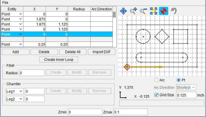
When profile shown above is saved as a "swept" solid model file and then brought into Vericut, the resulting "swept" solid model is shown in the picture below.
Zmin / Zmax — Used to specify the starting and ending location along the Z-axis when creating a "swept" solid model.
The following features are only available when the Sweep or Revolve Profile window is accessed from the Tool Manager. The specific features available will vary depending on the tool type (Mill, Turn, or Probe) and the tool component type (Revolved Cutter, Insert Cutter, or Holder) and the profile window type (Sweep or Revolve).
Color — Color that the tool component is to be displayed in Vericut. For additional information, see Tool Display Colors in the Tool Add/Modify window, Common Features section.
Do Not Spin with Spindle — Toggle On (checked), or Off (not checked), to specify whether or not the holder component spins with the spindle. For example, a milling tool holder would spin with the spindle, while a turning tool holder would not.
Flute Length — Used to specify the length of the cutter having flutes or teeth that can remove material.
Spindle Direction — Use to specify spindle direction for a specific revolved cutter. Choose CW (clockwise) or CCW (counterclockwise).
Thickness — Used to specify the thickness of the insert or holder (sweep profile only).
Alternate — When toggled "on" (checked) this feature designates the cutter that is being created as an "alternate" or "secondary" cutter for a particular tool assembly. This feature enables you to switch between a "primary" and "alternate" cutter shape, in order to support tools such as back-boring tools.
The AlternateTool macro is used to specify whether to use the "primary" (Override Value = 0) cutter shape or to use the "alternate" (Override Value = 1) cutter shape. See Create and Use Tools with Alternate Cutters in the Using the Tool Manager section of Vericut Help for additional information and examples.
📝 NOTES:
-
For additional information on these Tool Manager features, see the specific tool component in the Tool Definition window.
-
Also see Defining Profile Tool Shapes section of Vericut Help.
DXF Geometry window
Locations:
Profile Sketcher window > Import DXF
Project tab > Tools >  (DXF)
(DXF)
Opens the DXF Geometry window enabling you to import two dimensional geometry from files which comply with a de facto CAD system standard, the Data eXchange Format (DXF).
The DXF Geometry window is accessed in two areas of the Vericut software:
- Project menu > Setup > Models > right click menu > Add Model > Create Revolve/Create Sweep > Import DXF or Configure Models menu > Add Model > Create Revolve/Create Sweep > (Right Mouse Button in the Preview window) > Import DXF. This function is used to create profiles that can be rotated about an axis, or swept along an axis to create solid models for use in Vericut.
The DXF Geometry window that is accessed from the Profile Sketcher window will have slightly different options:
- Tool Manager > Import ribbon > DXF. The DXF Geometry window is also accessible in Tool Manager to Add/Modify cutters, inserts and holders.
Many of the features are common regardless of where the window was accessed from and have identical functionality, Those features that are specific to either of the Model menu windows or Tool Manager windows are noted in the feature descriptions below.
Importing DXF Profile Data:
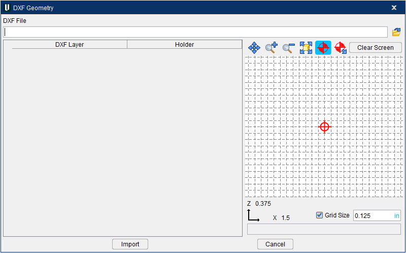
DXF File — Use to specify the DXF file containing the tool data. Enter the /path/filename in the DXF File text field or click on the  (Browse) icon and use the Select DXF File window to specify the/ path/filename of the file.
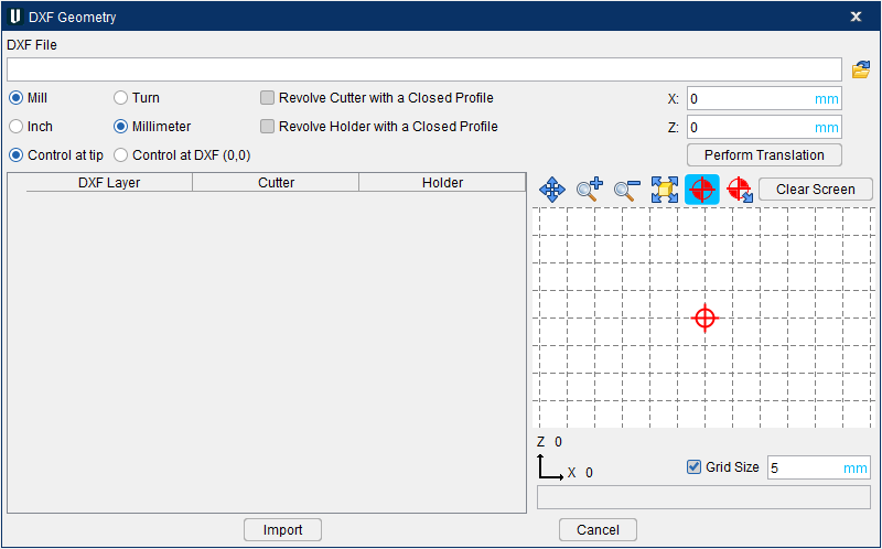
Mill / Turn — (Tool Manager only) Specifies the "type" of tool data being imported.
Inch / Millimeter — (Tool Manager only) Specifies the "units" of the tool data being imported.
📝 NOTE: Depending on what software created the DXF file it is sometimes inconsistent with containing the proper units value to read in and set accordingly. Because of this some DXF files may import incorrectly even with the Inch/Millimeter option set to what you believe it is. To easily resolve this once the tool has been imported, select the Tool ID > Tool Information tab > Units, then switch the units. You will be prompted to convert the tool values. Select Yes to “Convert” for (example, 25.4mm becomes 1 inch) or No to “Keep” (for example, 1mm becomes 1 inch) the values.
Control at tip/ Control at DXF (0,0) — (Tool Manager only) Specifies the "control point" to be used for the tool data being imported. Control at tip puts the control point at the tip of the tool (the point on the profile with the lowest Z value is assumed to be the tip of the tool). Control at DXF (0,0) puts the control point at the 0,0 point of the profile.
Revolve Cutter with a Closed Profile — (Tool Manager only) Creates a spun representation of the cutter when the cutter profile is completely closed. Leave unchecked if the closed profile is intended to be extruded (I.e. an insert)
Revolve Holder with a Closed Profile — (Tool Manager only) Creates a spun representation of the holder when the holder profile is completely closed. Leave unchecked if the closed profile is intended to be extruded (I.e. a stick tool holder for turning)
X translation / Y translation / Perform Translation — (Tool Manager only) allows for the geometry to be moved from the Control at tip or Control at DXF (0,0). Enter a value into either or both translation fields then click the Perform Translation button. The translation offset is an incremental movement. Once geometry is read in a negative X value will not be allowed as this translation would cross over the geometry.
Preview Grid icons
| Icon | Name | Action |
|---|---|---|
| Pan | Pan/translate- drag mouse in the direction pan | |
| Zoom In | Zooms in approximately 20% each time it is clicked | |
| Zoom Out | Zooms out approximately 20% each time it is clicked | |
| Fit | Fits the tool in the sketcher window | |
| Origin | When selected, displays the tool origin point | |
| Origin Translate | Allows for the dynamic movement of the tool origin point | |
| Clear Screen | When selected, unchecks all layer selections and clears the Preview Grid but retains the selected DXF file |
Component Table
After specifying the DXF file, a record is created in the Component Table for each layer contained in the file. You can re-order the records in the table by clicking on the button in the first column of the record and dragging it to the desired position.
DXF Layer — This column displays the name, or number, identifier of the layer.
Profile — (Create Model File only) This column is used to identify the profile that is to be used.
Cutter — (Tool Manager only) This column is used to identify the "cutter" geometry data to be imported. Click on the box in the appropriate layer row to activate it (checkmark is visible).
Holder — (Tool Manager only) This column is used to identify "holder" geometry data to be imported. Click on the box in the appropriate layer row(s) to activate it (checkmark is visible).
📝 NOTE: When the DXF Geometry window is accessed from the Tool Manager, only layers that have been indicated as "cutter" or "holder" will be imported. If the DXF window was accessed using Add > DXF Tool in the Tool Manager, only one "cutter" component can be imported, but multiple "holder" components can be imported for each tool record.
Import — Imports the geometry data into the appropriate Profile Sketcher window, or in the case of Add > DXF Tool in the Tool Manager, into the appropriate tool record/tool component.
Cancel — Use to close the DXF Tool Geometry window.
DXF File Requirements:
Only the ENTITIES section of a DXF file is scanned by Vericut. The BLOCKS section is ignored, so BLOCK references within the ENTITIES section will not be expanded. REPEAT entities are also ignored. The only geometric entity types processed are LINE, ARC, CIRCLE, POLYLINE, LWPOLYLINE, TRACE, SOLID, 3DLINE and 3DFACE.
For Creating Solid Models
Import "open" 2D profiles to be rotated about the Z-axis to create "revolved" solid models. Putting the start and end points of the profile off of the Z-axis will result in a solid model that is open in the center like the one shown in the "Revolved Solid Model" picture below. To create the model with a solid center, make sure that the start and end points of the profile are on the Z-axis.
| Open Profile | 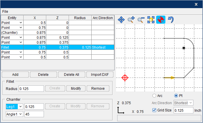 |
|---|---|
| Revolved Solid Model | 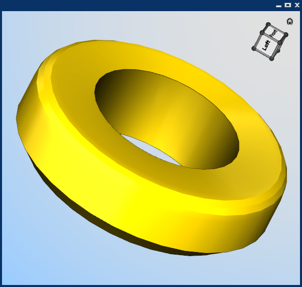 |
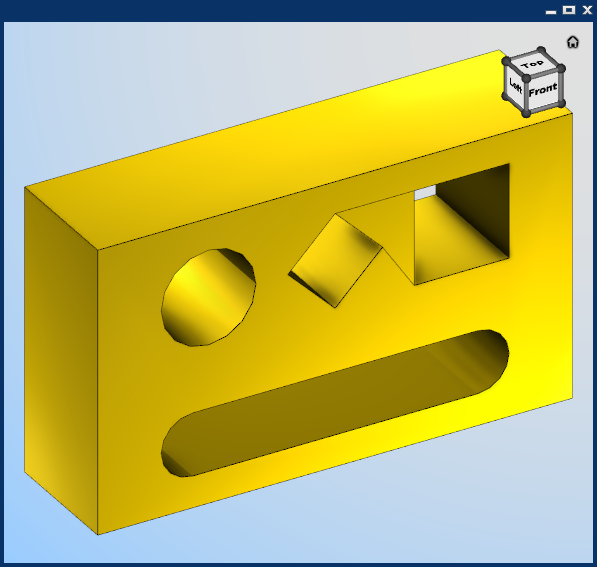
Import "closed" 2-D profiles to be "swept" a specified distance along the Z-axis to create a solid model or a cutter insert/holder.
| Closed Profile | 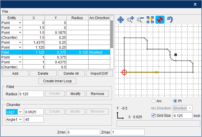 |
|---|---|
| Swept Solid model | 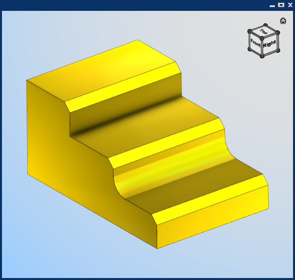 |
For Creating Cutters, Inserts and Holders
Vericut expects only one tool per DXF file. Each component (cutter or holder) of the tool should be on its own named or numbered layer. There can be no more than one cutter component, but multiple holder components are permitted. The DXF file may contain other layers which are unrelated to the definition of the tool's geometry. Within each component layer, LINEs, ARCs, CIRCLEs, POLYLINEs, LWPOLYLINEs, TRACEs, SOLIDs, 3DLINEs and 3DFACEs can be used to define the profile of the tool.
For a milling tool, the Y coordinate of the DXF data corresponds to the tool's axis of rotation, known as the Z axis in Vericut's Tool Manager. The X coordinate of the DXF data corresponds to the Tool Manager's X axis. An exception to this is a DXF file recognized by its use of layer names as being generated by TDM Systems', Tool Data Management (TDM) system. In such a file, the X-axis is the tool's axis of rotation, with the tool tip on the right, and the Y coordinate is the radial distance from the rotation axis.
DXF Data 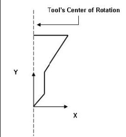 |
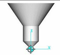
In Vericut 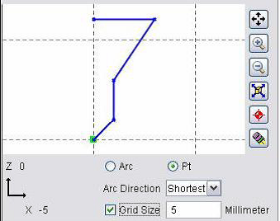 |
|---|---|
DXF Data from TDM 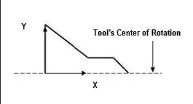 |
 |
DXF Data 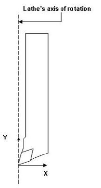 |
In Vericut 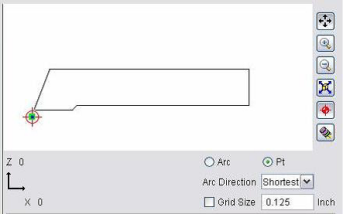 |
|---|---|
| Cutter on Layer 1 | 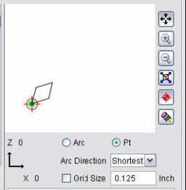 |
| Holder on Layer 2 | 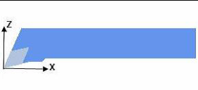 |
Configure Model menu, Translate tab
The features on the Translate tab enable you to translate the selected object by indicating "from" and "to" points to move the object. Movement occurs each time you press the Move button. If the applied movement is incorrect, press the Undo icon in the Project Tree Top Icon Bar to return the object to its previous location.
![]()
Translate tab features
From / To — Use to specify the locations to move the object from and to, relative to the machine origin. XYZ values can be entered (separated by spaces), or selected by clicking in the field then clicking on a model. As you move the mouse over the Vericut model, a crosshair and vector show you the pending pick-point location. Graphical selection supports picking corner points and midpoints of uncut model geometry, or virtually any point on machined features. The following feature options are available:
-
Vertex — Enables you to select one of six key points associated with the triangles representing the faces of a model. For each triangle, the points consist of the three vertices and the midpoint of each of the triangle's three sides. Vericut selects the point closest to your mouse pick.
-
Circle Center — Enables you to specify a circle center point. This feature is enabled in the following way:
-
Choose Circle from the pull-down list, and then click the arrow to enable selecting geometry in the graphics area.
-
Follow the prompts in the temporary message area above the Vericut Logger panel to define the circle center point.
- Pick the XY plane of the circle.
- Pick the cylinder/cone face that contains the circle.
-
The circle center point will be displayed in the graphics area and the coordinates of the center point will be displayed in the Location text field.
-
Component Origin — Enables you to select the origin of a chosen component. Use the Project tab > Axes to see component origin axes.
-
Model Origin — Enables you to select the origin of a chosen model. Use the Project tab > Axes to see model origin axes.
-
CSYS Origin — Enables you to select the origin of the chosen coordinate system axis. Use the Project tab > Axes to display the coordinate systems that are available.
-
3 Planes — Enables you to select a point represented by the intersection of three planes.
Move — Moves the selected object by the incremental distance, as calculated from the "From" point to the "To" point location.
Back — Moves the selected object by the incremental distance, as calculated from the "To" point to the "From" point location.
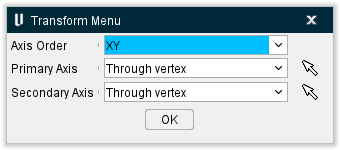
Transform menu — Use the ![]() icon to open the Transform Menu window, enabling you to create a transform menu.
icon to open the Transform Menu window, enabling you to create a transform menu.
![]()
Once the Transform Menu window is open, a new kind of CSYS will appear in the Graphics Area. This axis can be used to manually manipulate the CSYS from the Graphics Area.
![]()
The axis arrows translate the object along the selected axis. A guideline will appear showing you the axis that will be traveled.
The outer rings rotate the object around the central axis. A rotational circle will appear showing you how the object will rotate.
The inner planes translate the object along two adjacent axes. Two guidelines will appear showing you the axes that will be traveled.
The origin snaps the object to the center points, edges, and corners of other objects in the scene.
-
Translate — Use this field to manually enter the XYZ units you want the CSYS to move by.
-
Rotate — Use this field to manually enter the XYZ degrees you want the CSYS to rotate by.
-
Enable Translation Increment — Toggle this feature on (checked) to specify positional movements down to the decimal point. The adjoining dropdown menu will then become active and you can manually enter the number of decimal points or use the arrow bars to increase or decrease the numbers by 0.1.
-
Enable Rotation Increment — Toggle this feature on (checked) to specify degree rotations down to the decimal point. The adjoining dropdown menu will then become active and you can manually enter the number of decimal points or use the arrow bars to increase or decrease the numbers by 0.1.
-
Select Primary/Secondary Axis — This button opens the Transform Menu supplemental window enabling you to set primary and secondary axes.

-
Axis Order — Allows you to specify which axes to give priority. Options include XY, YZ, and ZX.
-
Select Primary/Secondary Axis — This button opens the Transform Menu supplemental window enabling you to set axis priority.
-
OK — Saves your selections and closes the window, returning you to the main Transform Menu window.
-
Reset — Undoes any changes made and closes the window.
-
Apply — Saves the changes made.
Reset — Undoes any changes made in the Transform Menu.
For Cut Stock models, the Translate tab will have two additional features:
Stock Material — This shows the Stock Material that is active. You can click the Change Stock Material button beside this field to open the Stock Material Catalog which will enable you edit the material.
Preserve Stock Transition — This button appears above the Add Model pulldown menu. Clicking it will set the CSYS to the current cut stock location even when the simulation is reset.
The remaining features on the Translate tab, referred to as “location features”, are common to all of the following Configure Model menu tabs (Rotate, Assemble, Matrix, Csys and Mirror) and show the selected object's position and angle, and can be used to move the object or verify its current location. Values are shown relative to the parent component, active Csys, or machine origin depending on the feature that is selected.
Angles — Use this feature to specify the absolute XYZ rotation of the object, separated by spaces.
A label, Mirrored, may be displayed on the Configure Model menu, Translate, Rotate, Assemble, Matrix, Csys and Mirror tabs below the Angles field as shown in the picture below.
![]()
This label indicates that the an odd number of mirror operations have been performed on the model and the model matrix stored in the project/machine file is left handed.
If Mirrored label is not displayed below the Angles field, it indicates that the model matrix stored in the project/machine file is right handed.
Show Location Relative to Parent — When selected, it indicates that the object location is shown relative to the parent component origin. Example follows.
Positioning a model — the model is moved relative to the component’s origin.
Show Location Relative to Machine Origin — When selected, it indicates that the object location is shown relative to the original coordinate system of the machine.
Position — This feature enables you to specify the absolute XYZ position of the object, separated by spaces.
This feature also enables you to use feature based selection as described under "From / To —" above. Feature based selection is only available when “Show Location Relative to Machine Origin” is selected.
Configure Model menu, Rotate tab
The features on the Rotate tab enable you to rotate the selected object about a rotation center point. Movement occurs each time you press one of the rotation direction buttons: X+/X-, Y+/Y-, Z+/Z-. If the applied movement is incorrect, press the Undo icon in the Project Tree Top Icon Bar to return the object to its previous location.
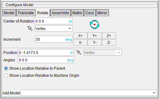
Rotate tab features
Center of Rotation — Enables you to use XYZ point location about which to rotate the object. XYZ values can be entered (separated by spaces), or selected by clicking in the field then clicking a position on a model. To see the center of rotation, press  . To remove the center of rotation symbol press the button again, or close the window. You can also use feature based selection to specify the center of rotation. See From / To on the Translate tab for additional information.
Increment — This feature enables you to specify incremental degrees of rotation to apply when one of the rotation direction buttons are pressed.
Rotation direction buttons — (X+/X-, Y+/Y-, Z+/Z-) When pressed, applies the incremental rotation specified in the Increment field. Rotation occurs about the Center of Rotation, relative to the machine origin.
The remaining features on the Rotate tab, referred to as “location features”, are common to all of the following Configure Model menu tabs (Rotate, Assemble, Matrix, Csys and Mirror). They are described in the Configure Model menu, Translate tab section.
Configure Model menu, Assemble tab
The features on the Assemble tab enable you to move the selected object by assembling (mating or aligning) it with other objects. Objects are assembled by mating or aligning one to three planar surfaces with surfaces on other models. If a non-planar surface is selected, Vericut constructs a tangent plane at the pick point. The relationship of surfaces being mated or aligned is known as a "constraint". If the applied movement is incorrect, press the Undo icon in the Project Tree Top Icon Bar to return the object to its previous location.
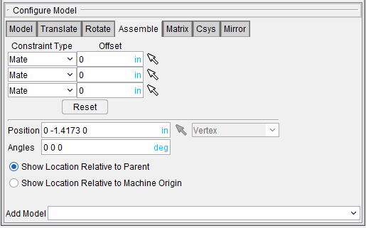
Assemble tab features
Constraint Type — Specifies how to constrain selected surfaces during object movement.
Options:
-
Mate — Moves the object so the selected surface opposes the surface selected on the second object (surface normals oppose each other).
-
Align — Moves the object so the selected surface is aligned with the surface selected on the second object (surface normals point in the same direction).
-
Align Cylinder — This feature can be used to align a component, or model, by the axis of a cylinder. The cylinder can be an STL model (if well defined) or a cut model. The cylinder surface can be either an inner surface (hole) or an outer surface (pin).
Follow the prompts in the logger to pick a common plane and two cylinders to align. Note that plane orientation must be same as the cylinder axis.
When second constraint is also Align Cylinder the component or model is rotated about satisfied constraint to achieve closest position of new constraint. The second constraint cannot be satisfied if the distances between holes or pins are different.
Offset — Use to specify a distance and direction (+ or -) in which to offset the constrained surfaces. The offset is applied normal to the surface.
Reset — Use to reset constraints to receive new data.
Follow these general steps to define a constraint for assembly:
-
For each constraint, click on
 , and then select the desired Constraint Type (Mate or Align) from the pull-down list.
 -
Specify an offset for the constraint if desired.
- Click on
 to put the constraint in pick mode so that you can select the surfaces to be constrained. The arrow will become highlighted as shown in the above picture for the second constraint.
 - In the graphics area, select a surface on the object to be moved.
- In the graphics area, select the surface to move the object relative to.
- After selecting the two surfaces to define a constraint, Vericut moves the object and indicates the satisfied constraint with a checkmark as shown in the picture above for the first constraint.
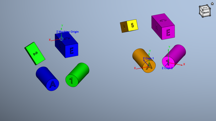
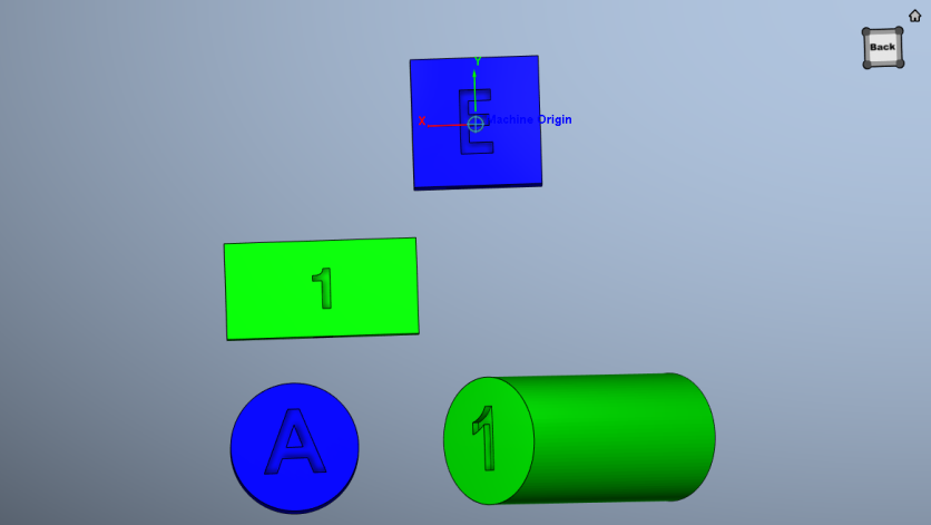
Consider the starting condition below for the examples that follow. The below image displays several surfaces that are not aligned or mated.
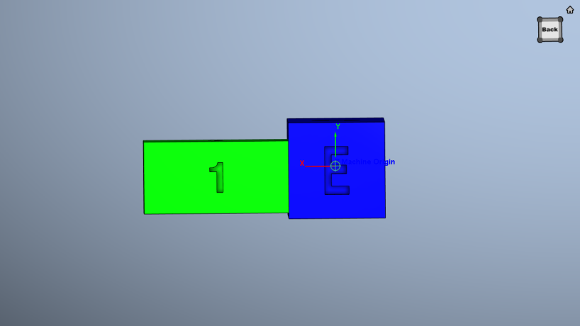
Mated surfaces — the right side of the green model is mated with the left side of the blue model.
Aligned surfaces — the green block is aligned with the blue block.
The remaining features on the Assemble tab, referred to as “location features”, are common to all of the following Configure Model menu tabs (Rotate, Assemble, Matrix, Csys and Mirror). They are described in the Configure Model menu, Translate tab section.
Configure Model menu, Matrix tab
The features on the Matrix tab enable you to move the selected object via a twelve parameter transformation matrix. If the applied movement is incorrect, press the Undo icon in the Project Tree Top Icon Bar to return the object to its previous location.
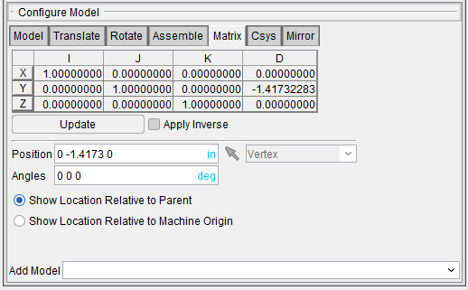
Matrix tab features
Matrix table — The transformation matrix table is similar to the matrix used in programming APT NC programs. Its twelve parameters reveal the geometric attributes of the local (transformed) coordinate system (CSYS) in terms of the machine origin.
The format of the matrix table is as follows:
| I | J | K | D | |
|---|---|---|---|---|
| X | I1 | J1 | K1 | D1 |
| Y | I2 | J2 | K2 | D2 |
| Z | I3 | J3 | K3 | D3 |
Each row represents an axis of the local CSYS. The first three columns represent the vector associated with each axis: I1, J1, K1 as the positive X-axis vector; I2, J2,K2 as the positive Y-axis vector; and I3, J3, K3 as the positive Z-axis vector. The fourth column values D1, D2, D3 represent the coordinates of the origin point of the local CSYS.
📝 NOTE: If you prefer to see the Matrix Table displayed with the I, J, K along the vertical axis and the X, Y, Z along the horizontal axis, set the environment variable, CGTECH_MATRIX_FORMAT=VERTICAL.
Update — Updates the object location to reflect the matrix table transformation. After updating, press OK or Apply to move the object.
Apply Inverse — When selected, inverts the matrix so that its twelve parameters reveal the geometrical attributes of the machine origin in terms of the local (transformed) coordinate system.
The remaining features on the Matrix tab, referred to as “location features”, are common to all of the following Configure Model menu tabs (Rotate, Assemble, Matrix, Csys and Mirror). They are described in the Configure Model menu, Translate tab section.
Configure Model menu, Csys tab
The features on the Csys tab enable you to translate the selected object from one coordinate system (CSYS) to another. Select the "From" CSYS and the "To" CSYS to move the object. Movement occurs each time you press the Move button. If the applied movement is incorrect, press the Undo icon in the Project Tree Top Icon Bar to return the object to its previous location.
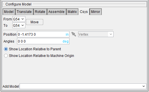
Csys tab features
From / To — Use to specify the locations to move the object from and to, relative to the machine origin. XYZ values can be entered (separated by spaces), or selected by clicking in the field then clicking on a model. As you move the mouse over the Vericut model, a crosshair and vector show you the pending pick-point location. Graphical selection supports picking corner points and midpoints of uncut model geometry, or virtually any point on machined features.
Move — Moves the selected object by the incremental distance, as calculated from the "From" point to the "To" point location.
The remaining features on the CSYS tab, referred to as “location features”, are common to all of the following Configure Model menu tabs (Rotate, Assemble, Matrix, Csys and Mirror). They are described in the Configure Model menu, Translate tab section.
Configure Model menu, Mirror tab
The features on the Mirror tab enable you to mirror a model about a specified axis (plane).
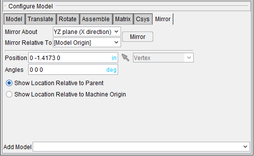
Mirror tab features
Mirror About — Use the features in the pull-down list to specify the plane that the model is to be mirrored about.
YZ Plane (X direction) — The Mirror attribute is set to mirror about the YZ plane.
| Before | After |
|---|---|
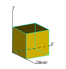 |
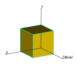 |
ZX Plane (Y direction) — The Mirror attribute is set to mirror about the ZX plane.
| Before |  |
|---|---|
| After | 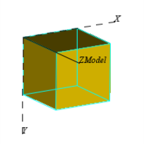 |
XY plane (Z direction) — The Mirror attribute is set to mirror about the XY plane.
| Before | |
|---|---|
| After | 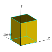 |
Mirror Relative To — Use to specify the coordinate system that the plane that you want to mirror about is related to. For example, the XY plane of the model origin. The pull-down list will contain the model origin (the default) and all available coordinate systems.
Mirror — After specifying the plane, and the coordinate system that it is relative to, press the Mirror button to make the mirror take place.
The remaining features on the Mirror tab, referred to as “location features”, are common to all of the following Configure Model menu tabs (Rotate, Assemble, Matrix, Csys and Mirror). They are described in the Configure Model menu, Translate tab section.