Distance/Angle group
Location:
Tool Manager > X-Caliper tab > Distance/Angle group
X-Caliper tab > Distance/Angle group
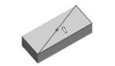
The command buttons in the Distance/Angle group are used to measure the distance and/or angle between any combination of two points, planes, conic axes, model or component origins, or edges formed by intersecting planes or cylinders. In general, select the "From" feature, then select the "To" feature. This forms a measurement line and the From point, middle, and To point are symbolized as drawings on that measurement line. The From point is represented by a plus sign, the middle by a circle, and the To point by a diamond as shown below:
 From /
  To groups — Each group includes the Feature, Location, and Direction used to specify what to measure from and what to measure to. Use the From / To arrows
 ![]() , to control which fields are filled in by screen pick data. You can select features on the Vericut model, or enter number values (separated by blank spaces) directly into the fields in the Settings group. After selecting the From feature, Vericut automatically transfers control to the To group. After selecting the To feature the Vericut Logger panel displays the measurement data.
, to control which fields are filled in by screen pick data. You can select features on the Vericut model, or enter number values (separated by blank spaces) directly into the fields in the Settings group. After selecting the From feature, Vericut automatically transfers control to the To group. After selecting the To feature the Vericut Logger panel displays the measurement data.
-
 Feature dropdown menu — Controls the types of features to measure between. Select the Feature type from the pull-down list. The default feature is Point until a new feature is selected. Feature descriptions:
 -
Point — The X, Y, Z of the pick point or entered point coordinates.
-
Plane — A flat, unbounded surface. If a curved surface is selected, data retrieved represents a plane tangent to the selected model surface at the pick point.
-
Axis — Centerline of a cylinder or conic.
-
Edge — Edge formed by two intersecting planes or parallel cylinders. Special cases follow.
-
Vertex — Enables you to easily select one of the six key points associated with the triangles representing the faces of a model. For each triangle, the points consist of the three vertices and the midpoint of each of the triangle's three sides. Vericut selects the point closest to your mouse pick. If the mouse pick is over the cut stock, Vertex works in the same way as the Point feature described above.
Vertex is a useful tool for measuring the trace of tool/fixture collisions on uncut fixtures. -
Model Origin — Origin of a selected model. Use the Project tab > Axes to see model origin axes.
-
Component Origin — Origin of a selected component. Use the Project tab > Axes to see component origin axes.
-
CSYS Origin — Origin of the selected coordinate system axis. Use the Project tab > Axes to display the coordinate systems that are available.
-
CSYS Axis — The X, Y, or Z axis of the selected coordinate system. Use the Project tab > Axes to display the coordinate systems that are available.
-
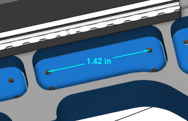
Circle Center — Use this feature to specify a circle center point to be used as a From or To feature.
-
Choose Circle Center from the pull-down list, and then click the arrow
 to enable selecting geometry in the graphics area.
 -
Follow the prompts in the temporary message area above the Vericut Logger panel to define the circle center point.
- Pick the XY plane of the circle.
- Pick the cylinder/cone face that contains the circle.
- The circle center point will display in the graphics area and the coordinates of the center point will display in the Location text field in the Vericut Logger panel.
-
-
Toolpath Trace — Use this feature to specify the toolpath you would like to take measurements from. This feature is only available when NC Program Review is active.
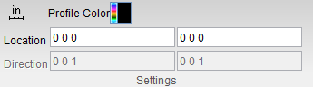
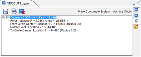
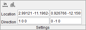
Measurement results are displayed in the Vericut Logger panel. Data output includes the From / To values input and the measured distance and/or angle. Location and Direction results are also displayed in the X-Caliper Settings group as shown below:
The following features are unique to Tool Manager's X-Caliper tab:
Tool Profile — Use this feature to specify the tool assembly as the point of measurement.
Bounding Plane — Use this feature to specify a tangent plane (XY ot ZX or YZ) of a model (insert or holder) as the point of measurement.
Measurement results are displayed in the Vericut Logger panel. Data output includes the From / To values input and the measured distance and/or angle. Location and Direction results are also displayed in the X-Caliper Settings group as shown below: