View Tab
The View tab contains various features that control how the graphics in Vericut are displayed. All features will be summarized on this page but each hyperlinked feature also has a dedicated full page description that you can click on to be navigated to for more information. A primer on Views can be found in Vericut Views
Layout group
The Layout group features control how many views of the Vericut model are seen and how they are arranged
Saved Layout group
The Saved Layout group is used to store, activate or deactivate, and choose between layouts.
Simulation Settings group
- No Animation — turns off all animation. This reduces processing time. No Animation can be toggled on or off while the simulation is running. When No Animation is toggled "on", the graphics display is not updated until either processing is complete or you Stop the processing. At that time the cut model is displayed in it "final" state or the state that it was in when processing was stopped. You can also toggle No Animation On/Off using the No Animation icon in the Vericut toolbar.
-
Resolution — controls the quality of cut model display. Increasing resolution displays a more accurate representation of the cut model, and requires more computer resources and processing time to display and manipulate the model. A coarse display resolution is automatically used when dynamically manipulating the model, such as rotation, zooming, etc. When the dynamic action is finished, the display is upgraded to the previous resolution. Options:
-
Manual — A display resolution which allows most models to be manipulated with acceptable performance and display quality.
-
Auto — Automatically sets display resolution based on viewing distance from the model. Resolution automatically increases when you zoom closer to see details on the model, and decreases as you zoom out.
View group
-
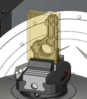
Stock/Design View — displays translucent Stock and solid Design, regardless of the component translucency settings. When the user clicks out of this temporary view state, then the component/model visibility goes back to what it was before that option was engaged. This feature can also be accessed from the Project tab. Here is an image of an active Stock/Design view:
-
Section — opens the Section window enabling you to define section planes through a Vericut model in a workpiece view.
- Lock Spin Center — Use this command button to set the Spin Center for Tool Manager or Assembly Manager as applicable.
-
View Orthoganal — Snaps the current view to the closest orthogonal view.
-
Reverse — Reverses the current view. See Reverse a View section of View Orient window for more information.
-
View Attributes — Opens the View Attributes window enabling you to control the display characteristics of a view.
-
View Orient — Opens the View Orient window enabling you to orient the view, including: rotate, zoom, pan, reverse, and more.
Zoom/Fit group
-
Zoom In — Zooms in by 20%.
-
Zoom Out — Zooms out by 20%.
-
Zoom to Box — Left-click and move mouse to trap area to zoom into (press <Esc> to interrupt rubber-banding)
-
Zoom Box in New View — Similar to Zoom (standard mode) described above except a new view is created to display the zoomed area.
-
Fit — Fits object in active view.
-
Fit All — Fits objects in all views.
Dynamic group
-
Dynamic X Rotation — Sets your rotation to maneuver along the X axis. See the To dynamically rotate a view section for detail.
-
Dynamic Y Rotation — Sets your rotation to maneuver along the Y axis. See the To dynamically rotate a view section for detail.
-
Dynamic Z Rotation — Sets your rotation to maneuver along the Z axis. See the To dynamically rotate a view section for detail.
-
Dynamic XY Rotation — Sets your rotation to maneuver along the X and Y axes. See the To dynamically rotate a view section for detail.
-
Dynamic Pan — Sets the view so that you can left-click and drag the mouse in the direction that you want to pan up, down, left, and right. See To dynamically pan section for detail.
-
Dynamic Zoom — Sets the view so that you can left-click and drag the mouse in the direction that you want to zoom in and out. See the To dynamically zoom section for detail.
Display group
-
View — Changes the graphical display. See the To change the view type to display a workpiece, machine, or combined view section for detail.
-
Draw Mode — This pulldown menu controls the Draw Mode of the view.
-
Background — Changes the shading of the background.
- Spun Tool Display — When active, displays what tools look like when they are in motion (spinning). When inactive, displays tools as static. This only affects the visual display, not the simulation.
- Spun Part Display — When active, displays what parts look like when they are in motion (spinning). When inactive, displays parts as static. This only affects the visual display, not the simulation.
-
Ambient Occlusion — When active, approximates how bright light should be shining on specific surface parts.
-
Refine Display — improves the image quality in the Graphics Area.
-
Axes — Opens the Axes window enabling you to control when various axes and coordinate systems are displayed.
Translucency group
The Translucency group features are used to specify how translucent or opaque the view will be as well as determine whether the slider setting will apply to one view or all views through the Apply to All Views checkbox. The functionality is identical to that of the Translucency slider on the View Attributes window.