Annotated Images window
Locations:
Project Tree > Setup Branch Right Mouse Shortcut Menu > Report > Annotated Images
X-Caliper tab >  (Annotated Images)
Toolbar short cut: ![]() (Annotated Images)
(Annotated Images)
The features in the Annotated Images window enable you to add new dimensions or notes to, or edit existing dimensions or notes in a setup plan. The dimensions are placed on a dimension plane (referred to as "the glass") represented by the XY plane of the specified Csys. The "end product" of Setup Plans in Vericut's Annotated Images is a report, or set of reports, which can be used to describe how the job is to be setup on a CNC machine for a part.

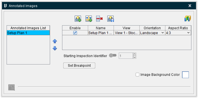
Annotated Images List
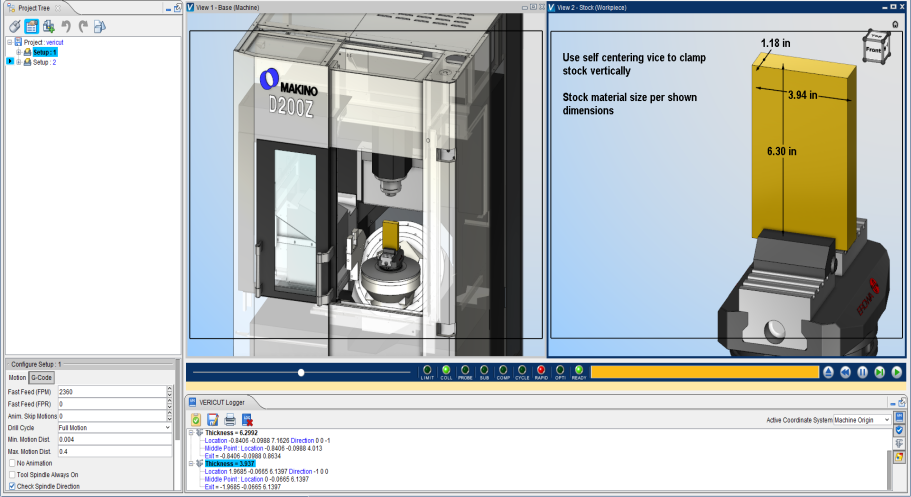
The Annotated Images List allows you to capture various images of a simulation that are needed to use in documentation to explain how to setup a job, show various stopping points of a program where measurements of the part may need to be taken, a fixture change takes place (i.e. removing clamps), as well as showing the finished state of the part being machined. The View layouts captured within Setup Plan can be independent from a view layout being used to observe the simulation. Multiple View layouts can be used depending on what is needed to help explain setup instructions.
This list contains a complete list of all setup plans that have been created. This list can be added to ( ), items on the list can be deleted (
 ), or the list can be saved (
 ) using the respective toolbar icons. Additionally, an inspection report can also be created (
 ). The
  up and
  down arrows allow for multiple captured annotation images to be reordered for Report output if desired
View Table
Each record in the View Table represents a setup plan image that can be added to a Vericut report. Each record consists of the following columns of data:
Enable — Toggle this feature on (checked) to make the individual view visible in the Graphic Display Area. Toggle this feature off (unchecked) to make it no longer visible.
Name — Displays the chosen name of the view and can be manually edited.
View — Lists the view type (Workpiece, Machine, or Profile).
Orientation — Defines whether the view will be in Portrait or in Landscape. Click on the cell to change the orientation by selecting your choice from a pulldown menu that appears.
Aspect Ratio — Choose between several different ratios including 4:3 (default), 3:2, 1:1, and 16:9. Click on the cell to change the orientation by selecting your choice from a pulldown menu that appears.
Starting Inspection Identifier — For use only with Inspection images. Toggle ON to set a starting value for the Identifier numbers for that image. As dimensions are added to the View, the Identifier number will start with the value set for that particular View.
Set Breakpoint — A breakpoint is used to define a stopping point in an NC program so an image can be captured. For example, setting a breakpoint would be used if an image and instructions for a report need to be created for fixture clamps to be removed at a specific point in the NC program.
 (Preview Captured Image) — Once a view has been enabled, you can highlight the whole row and then the binocular icon will become active. By clicking on this icon, you can preview the view that has been set up. As long as the icon is active, selecting between different views will automatically change the preview to that view.
NOTES:
- Any functions on the X-Caliper ribbon (Feature History, dimensions, notes) can be displayed in any view and captured when saving a view.
- Any Feature History, dimensions, and notes that have been saved within a view can be modified, moved, deleted, etc. then the view can be saved again to update the image.
-
Feature/History, Distance/Angle, Hole Depth, and Stock Model Info dimensions along with Notes can all be used in Setup Plan views and captured to be used in a Vericut Report.
-
Dimensions and Notes can be edited by Left Mouse Button clicking on any of the text displayed. Extra Settings in the Dimensions Group can also be used to manipulate various aspects of the dimenions.
Inspection
Introduction to Inspection
Setup Plan and Inspection functionality within Annotated Images are very similar in functionality of setting up and saving views to use in a Vericut Report.
The "end product" of Vericut's Inspection module is a report, or set of reports, which define the inspection operations to be performed on a part. Typically these check measurements are made while the part is still on the machine, perhaps after each tool's activity to ensure that the job is proceeding as intended. If a discrepancy is found, no additional time will be wasted on subsequent machining. This goal can be reached quickly if the inspection is performed during the machining process. Inspection can also be used to describe the measurements of a completely finished part for your quality department. GD&T can be added to any dimension including datum callouts.
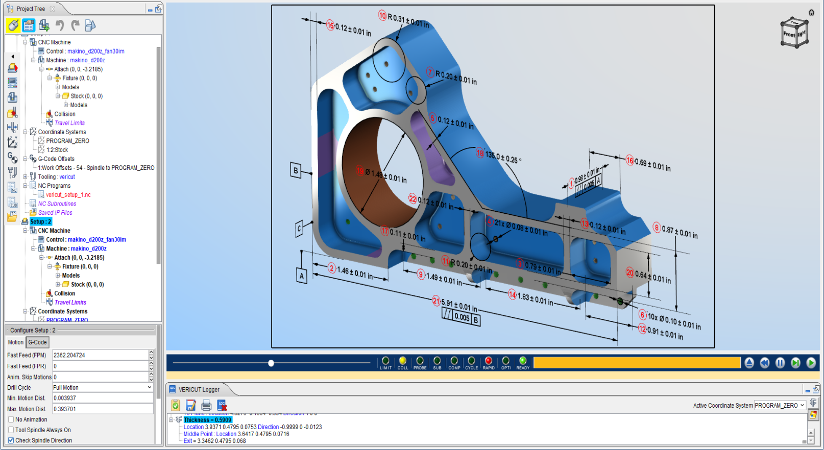
The features in the Annotated Images window enable you to capture both Setup Plans and Inspection images for use in a report or set of reports. Images can include 3D dimensions, GD&T, notes, model sections, and model orientation.
Important Concepts
Annotated Images List — The Annotated Images List allows you to capture various images of a simulation that are needed for use in documentation to explain how and where to measure important dimensions. These images can show GD&T along with datum planes. The View layouts captured within Inspection can be independent from a View layout being used to observe the simulation. Multiple View layouts can be used depending on what is needed to help explain the inspection instructions.
Starting Inspection Identifier — Can be used to set the starting number for labeling the inspection dimensions for that particular image. See Identifier Numbers section below for additional information.
Set Breakpoint — A breakpoint is used to define a stopping point in an NC program so an image can be captured. For example, setting a breakpoint would be used if an image and instructions for a report need to be take a dimension at a particular point in the NC program.
Image Background Color — Check ON to control the background color in the captured images.
X-Caliper Features, Dimensions, and Notes in Inspection — Feature/History, Distance/Angle, Hole Depth, and Stock Model Info dimensions along with Notes can all be used in Inspection views and captured to be used in a Vericut Report.
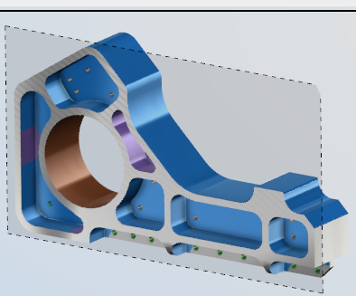
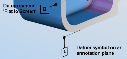
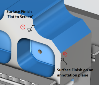
Manipulation of the Dimension Display — Dimensions, Datum symbols, and Notes can be displayed ‘Flat to Screen’ or oriented to align with an annotation plane. By default, dimensions will display ‘Flat to Screen’.
If you want the dimension, datum symbol, or Note to be oriented to a specific plane, set an annotation plane by using X-Caliper > Dimensions group > Show Annotation Plane > then select a surface on the 3D model. This annotation plan will remain modal until another annotation plane is selected or it is removed.
If the text in dimensions, datum symbols, and notes when aligned to a specific annotation plane is not displayed in the desired orientation, the text can be easily manipulated to display as you need. There is a spin icon above the selected dimension to dynamically drag the text around 360 degrees. When you left mouse button on the dimension there is also Rotate Text options to flip or align the text accordingly. These changes will remain modal for the following dimensions created until a change in text orientation is made.
Dimension Modifications
Inspection dimensions can be manipulated to display tolerances, GD&T, along with other changes. Left mouse button click on a displayed dimension to get the following options.
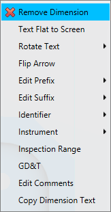
Text Flat to Screen/Text Aligned to 3D Plane — Adjusts text or dimension so it is flat to the screen instead of aligned with an annotation plane. Option is only displayed in the menu when an active annotation plane exists.
Rotate Text — Allows for rotating or flipping of text or dimension vertically, horizontally, or align with other text if the text is not oriented as desired. Option is only displayed in the menu when a dimension was created on an annotation plane.
Flip Arrow — Allows for flipping the leader arrows to better display the dimension.
Edit Prefix — Allows for a prefix to be added or selected before the dimension.
Edit Suffix — Allows for a suffix to be added or selected after the dimension.
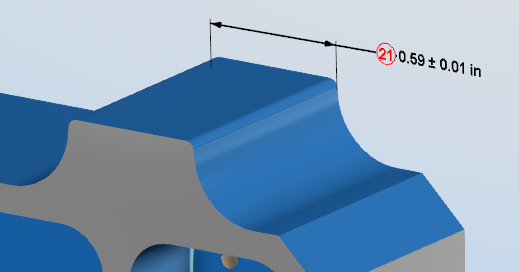
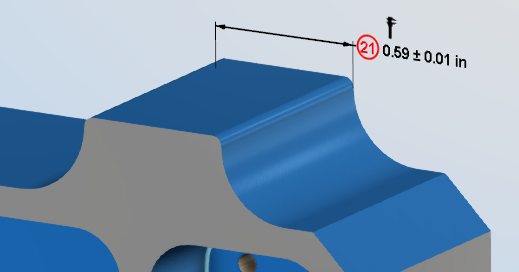
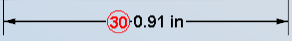
Identifier Numbers — When a dimension is added in Inspection an identifier number is automatically added to each dimension displayed in a red circle.
During dimension creation, if certain dimensions are created and then deleted, the Identifier numbers may not initially display in numerical order. To automatically reorder the Identifier numbers toggle ON the Starting Inspection Identifier option in the Annotated Images window. When Save Annotated Image is clicked the Identifier numbers will renumber in sequential order as they were created.
Identifier numbers will start numbering at 1 for each specific Inspection image. If you need to control the start number for each Image this can be done using the Starting Inspection Identifier field.
If a specific Identifier number is needed on any Inspection dimension, left mouse button click on the dimension and edit the Identifier number field.
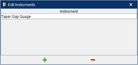
Instrument — This Edit option allows the user to add custom Instruments to a list that is now stored in the .prefs file for reuse on other projects. When you select Edit… > you get a window that allows you to add/remove custom instruments. You can also open the pulldown menu to see a default list of 12 instruments to select from.
When an instrument is selected or created to use, it is marked with a “caliper” icon above the dimension to denote the dimension has been assigned an instrument. The “caliper” icons display on the screen but do not get captured to display in Vericut reports and images.
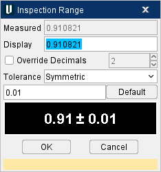
Tolerances
Default Tolerances — Default tolerances for each dimension are defined under the Extra Settings option in the X-Caliper Dimensions group.

Tolerances for each dimension can edited as necessary by Left Mouse Button clicking on that dimension.
Inspection Range
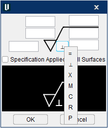
Dimension Tolerance Types — Vericut supports all methods to display tolerances in X-Caliper for dimensioning within Setup Plan and Inspection. To adjust the tolerance display, Left Mouse Button on the dimension > Tolerance
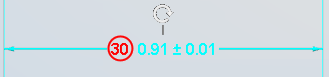
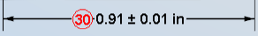
Symmetric (Bilateral-Equal) — (Default tolerance display method) Displays single ± tolerance value with the dimension.
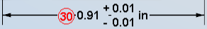
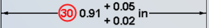
Plus Minus (Unilateral, Bilateral-unequal) — Allows for minimum and maximum tolerance values to be displayed.
Not Displayed — Does not display any tolerance for that dimension.
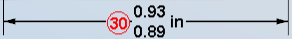
Maximum Minimum — Allows for +/+ or -/- tolerance values to be displayed.
📝 NOTE: This tolerance method does not verify the displayed value is within tolerance range.
Limit Dimension — Set under X-Caliper > Dimensions group > Extra Settings > Check ON Display Limits. Allows for displaying only the minimum and maximum values of the dimension to pass inspection.
GD&T and Datums within Inspection
Datums — Datum symbols can be added to Inspection images to denote datum callouts for GD&T. Datums can be aligned with annotation planes if desired or left ‘Flat to Screen’. To place a datum symbol on a model select the Set Datum Reference icon ![]() in the X-Caliper > Dimensions group while in Inspection.
in the X-Caliper > Dimensions group while in Inspection.
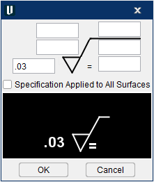
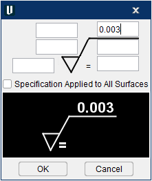
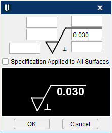
Surface Finish — Surface Finish callouts can be added to Inspection images to denote special surface finishes on a part. Surface Finish callouts can be aligne with annotation planes if desired or left ‘Flat to Screen’. To place a Surface Finish symbol on a model select the Add Surface Finish icon in the X-Caliper > Dimensions group while in Inspection.
The Surface Finish window supports the following options for a surface finish callout. To add additional callouts to a surface finish or to make changes, hover over the surface finish symbol > Left Mouse Button click > Edit Surface Finish.
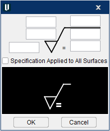
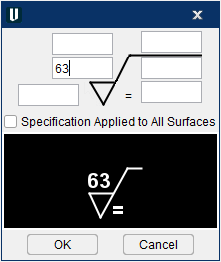
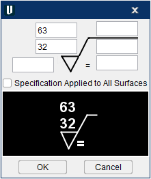
Roughness average value can be stated in microinches, micrometers, or roughness grade by entering the appropriate text into the following field.
Minimum and maximum roughness average value can be stated in microinches, micrometers, or roughness grade by entering the appropriate text into the following field.
Machining allowance can be stated in inches or millimeters by entering the appropriate text into the following field.
Maximum wave height can be stated in inches or millimeters by entering the appropriate text into the following field.
Maximum wave spacing can be stated in inches or millimeters and can be added by entering the appropriate text after the maximum wave height.
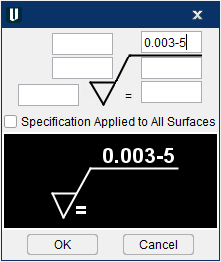
Roughness cutoff can be stated by entering the appropriate text into the following field.
Roughness sampling length can be stated in inches or millimeters by entering the appropriate text into the following field.
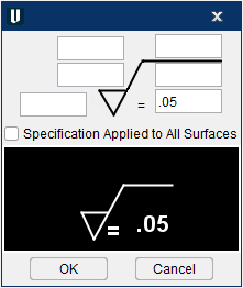
Lay symbol can be changed by hovering over the symbol > Left Mouse Button click to get a list of the available options.
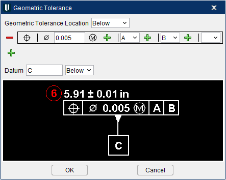
Feature Control Frames — Geometric tolerancing can be added to any dimension as necessary when creating an Inspection image. To add GD&T to a dimension, hover over the text of the dimension > Left Mouse Button click > GD&T
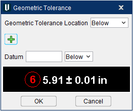
The Geometric Tolerance window supports the following Feature Control Frame
Single Frame — Single Frames are made up of a single characteristic and tolerance zone callout with up to three datum references. To add a single Feature Control Frame click the green plus  .
.
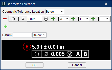
Composite Frame — Composite Frames have a single characteristic, but multiple lines of tolerance zone and datum reference callouts inside of multiple frames. To add a Composite FCF click the green plus below the first frame. Then select the same characteristic symbol as the first FCF.
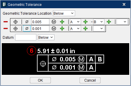
Multiple Frame — Multiple Frames have multiple characteristic, tolerance zone, and datum reference callouts. Each unique characteristic in a multiple frame denotes a unique FCF

The Geometric Tolerance window also supports special conditions if a FCF is also a datum.
Comments — Comments can be added to each inspection dimension if specific instructions are needed. These comments can be output into a table within an inspection report. To add a comment to an inspection dimension, hover over the dimension > Left Mouse Button click > Edit Comments.

Copy Dimension Text — Copies the displayed dimension, tolerances, etc. in a text format to the clipboard to paste in another application.