Introduction to Vericut
Vericut simulates or replaces costly steps of the NC data verification process, plus optimizes the efficiency of material removal. By simulating NC programs, Vericut can reduce or eliminate the time-consuming and expensive steps of the traditional data prove-outs. The program also optimizes program feed and speeds to increase the efficiency of the machining process. This all adds up to lower costs and higher profits for your business.
Need training? Visit the Vericut website at https://vericut.com and click Training, in the Services pull-down menu, for training course descriptions, schedules, and online registration.
NC program verification process with Vericut:
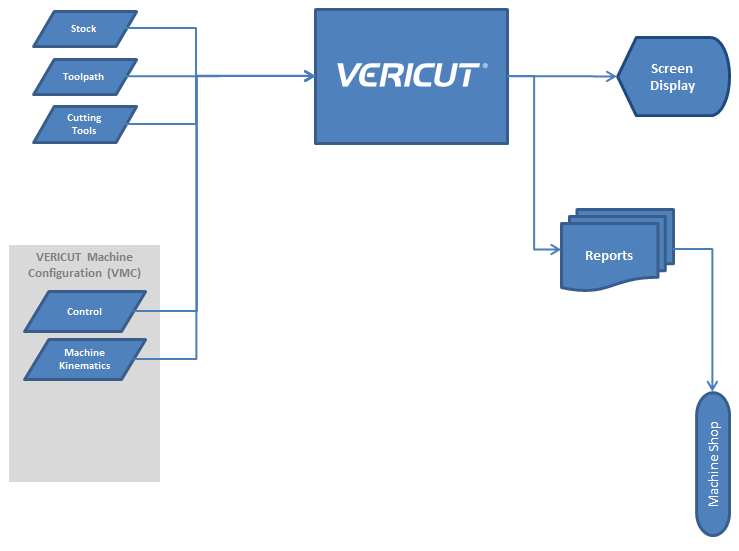
Vericut interactively simulates the material removal process of NC program data. Instead of messy wax or foam models, or costly prove-outs that waste valuable production time, a simulated Vericut part is graphically produced on your computer screen. Vericut then verifies the accuracy of the NC program and makes certain the finished part matches the design model. Before any machine time is spent, Vericut catches discrepancies that could corrupt the cutting process and identifies the responsible NC program records for fast and easy adjustment.
The input into Vericut is NC program data from almost any source. G and M code data as well as APT type CL-files are directly processed by Vericut. Similar to the requirements of machining a real part, Vericut needs the NC program data, a description of the raw stock material to be machined, and descriptions of the cutting tools used to machine the part. The result of the verification process is a solid model of the machined part and an error Log file reporting any machining errors detected during the simulation. The Vericut model can be inspected, saved, or used as the stock material for another NC program.
In addition to streamlining the verification process, Vericut dramatically boosts productivity on the shop floor. Automated and user-selectable optimization settings in Vericut let you maximize the material removal process. The feed rate and cutting speed of each NC program automatically adjust based on the depth, width, and angle of each cut. In fact, you can even set Vericut to compensate for dull or custom cutters or other elements unique to your operation.
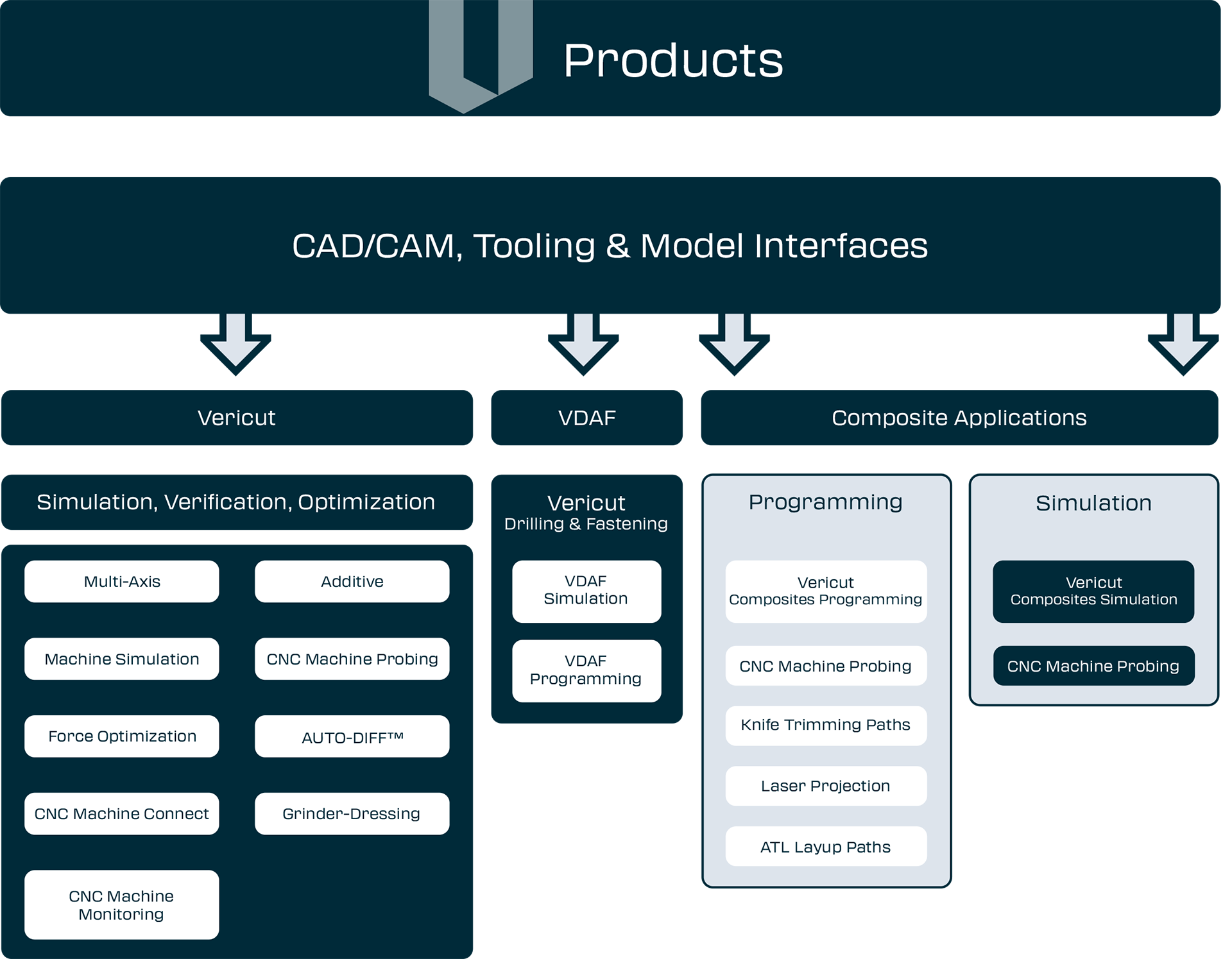
Vericut simulates up to 5-axis milling, drilling and wire EDM operations, as well as turning and combination mill/turn machining. With a complete line of specialization modules for added features and functionality, Vericut is truly the total simulation, verification, and optimization solution for unleashing NC productivity.
Installing Vericut
In most cases installing Vericut is a straight-forward and easy task, requiring only a few minutes of time. Prior to installing any software, review the system requirements and the installation procedure for the computer type on which you intend to operate Vericut.
Detailed step-by-step instructions are provided in Installing Vericut Products included online in the Vericut Help Library. Follow all applicable steps to ensure smooth Vericut installation and successful operation.
Vericut Licenses and Options
Vericut licenses and capabilities differ, depending on the environment in which Vericut is being operated. A modular approach provides the flexibility to purchase only the capabilities you need. As your needs change, you can add the appropriate licenses to increase Vericut's functionality. The terms "licenses" and "options" are synonymous, since each option for Vericut is licensed by Vericut. It is not necessary to install any additional software to add an option. Vericut provides a license that allows immediate access. See Product Line, on the Vericut website, for complete details on available options.
Vericut software licenses allow you to share Vericut over a network. Only one user may access a given license at a time. Vericut's license system supports XP, XP64, Win7, and Win7 (64). See Vericut System Requirements, on the Vericut website, for more detailed information. The server and networked workstations can be different computer types.
Licensing for Vericut
Vericut 9.7 licensing is required. If you do not have a current license, obtain licensing from Vericut as described below.
Licenses are issued via email only. Your license will be emailed to the primary Vericut user at your company. If you do not have licensing, submit an application via Vericut website.
Note to new customers — You will need to know the computer ID (Ethernet address) of the computer on which the Vericut Network License Server is to operate. To determine the computer ID, see the steps described in the Installing Vericut Products section of the Vericut Help Library. (ref. Determine Your Host ID and Request a License).
Vericut with SpaceMouse
Vericut supports 3Dconnexion 6 axis input devices (SpaceMice) on Windows. Use of these devices requires a driver known as 3DxWare.
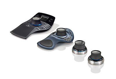
A configuration file (Vericut.scg) is required and is accessed by the 3DxWare driver on startup. This file is distributed by 3Dconnexion with the most recent version of their driver.
While beta testing has shown that Vericut generally works correctly with various older models and older versions of the device drivers, Vericut recommends using the latest driver version. It can be downloaded from https://3dconnexion.com/. The Vericut configuration file was added to 3DxWare version 2.3 build 5, September 4, 2002.
📝 NOTE: 3Dconnexion motion control devices currently work with Vericut on Windows platforms only.
Performance Considerations
This section describes ways to help increase Vericut productivity.
System considerations
Computer speed — Vericut runs faster on faster computers. When comparing computers made by different manufacturers, you can get a general idea how Vericut will perform by comparing the processor speed for floating point computations.
Multiple processors — Vericut runs 10-20% faster on computers with dual processors over a comparable computer with a single processor.
Memory — The amount of memory available to Vericut can make a difference. See "Vericut System Requirements" for memory recommendations. If you intend to process large tool paths, complex cutting operations, or use AUTO-DIFF, you may need more memory. Vericut uses virtual memory (hard disk) when physical memory (RAM) is exhausted. Best performance is obtained when sufficient physical memory is available to Vericut. Excessive memory does not make Vericut run faster, however, insufficient memory will slow it down.
Running concurrently with other applications — Even though your system may run Vericut or other large applications (e.g. CAD/CAM packages) comfortably, running them concurrently may cause competition for resources: memory, disk space, etc. Under these conditions the computer begins "paging" or "swapping" memory (a.k.a. "disk thrashing"), which adversely affects performance. Symptoms of disk thrashing are: constant hard drive activity or noise, active applications are slow, "Out of memory" error messages or warnings appear. In the worst case you can run out of all available memory which can cause your computer to crash or hang. When determining the amount of memory the system needs to run your applications, be sure to consider the memory requirements of ALL applications that will be run concurrently.
Graphics cards — Vericut uses 2-D raster (pixmap) graphics. It does not use triangle shading (such as with a 3-D API like OpenGL or Direct3D), texture mapping, or much (if any) vector drawing. All graphics cards (even the cheapest) do pixmap graphics. The card needs enough display or video memory to drive the display resolution at the desired number of colors. For example, 8 mb of display memory may be enough to do a 1024 x 768 display at True Color, but may only be able to do 64k colors at 1600 x 1024 resolution. Vericut 5.0 or higher performs best in a True Color display environment. More expensive does not necessarily mean "better for Vericut". Lower cost cards frequently outperform expensive cards when running Vericut.
Tolerances
Cutting Resolution — The "Cutting Resolution" value (ref. Project tab > Settings > Properties tab) controls the accuracy of cuts applied to the workpiece. This value directly affects the speed and quality of the results from comparing or exporting models, optimizing tool paths, checking for holder collisions, "Fast Feed" errors, dynamic rotation speed, and zoom speed. A larger Cutting Resolution value makes Vericut go faster, but the resulting cut model and collision checking will be less accurate. A smaller Cutting Resolution value may slow the simulation, but provides the high level of accuracy needed to perform detailed model analysis or export, optimization, etc.
- A larger Cutting Resolution value is probably okay for quick visual checks, or when only X-Caliper will be used to analyze the model (no AUTO-DIFF).
- Use a smaller Cutting Resolution value if you expect to use AUTO-DIFF, Model Export, Optimization, or examine very small model details.
Model file tolerances — Model files, such as Stereo lithography (STL) or Vericut model files, exported from CAD systems should be created using tolerances appropriate for how they will be used in Vericut. For example, models that will be used as stock workpieces, holding fixtures, or NC machine components probably do not need to be as accurate as models that will be used by AUTO-DIFF to check for gouges or excess material. Outputting CAD models with excessively small tolerance values can result in very large model file sizes that cause Vericut to use large amounts of memory. Similar considerations apply to tolerances for converting IGES model files that will be used in Vericut. Assuming you have enough memory, model file size/complexity does not affect cutting speed in Vericut.
Other tips and tricks
Axes display — Axes displayed in the graphics area (e.g. via Project tab > Axes or right-click shortcut menu) slow cutting speed. For best performance clear all axes before cutting.
Fixture display — Fixtures displayed in the "Workpiece" view slow cutting speed. For best performance, set Visibility to Machine View on the Component Attributes tab of the Modeling window. (e.g. via Project Tree > Project menu > Setup Models > Define: Component Attributes tab or double-click on the fixture component in the Component Tree)
Skip Motion and Animation Speed control — Features on the Animation Slider directly affect cutting speed. Skipping cuts can make Vericut run faster by updating the display less frequently, especially when multi-axis cuts, large cutters, or tools with holders are involved. Also, for best performance ensure the Animation Speed slider, located at the bottom of the Vericut main window, is positioned as far right as it will go ("Fast").
No Animation — This feature, on the Project tab > No Animation, enables you to reduce processing time. When No Animation is toggled "on", the graphics display is not updated until either processing is complete or you Stop the processing. At that time the cut model is displayed in it "final" state or the state that it was in when processing was stopped. You can also toggle No Animation On/Off using the No Animation icon, ![]() , in the Vericut toolbar.
, in the Vericut toolbar.
Tool holders — Using tool holders enables Vericut to detect when non-cutting portions of the tool assembly remove material or crash into clamps/fixtures holding the workpiece. You can minimize this effect by modeling only portions of the tool assembly that can be involved in a collision. For example, don't bother modeling the taper of a milling tool holder (portion that seats inside the spindle). If you don't have concerns about tool holder collisions, Vericut will run faster if tool holders are not displayed, e.g.: Project Tree > Configure Tooling menu > Holder Visibility features clear the "Display Holders in Workpiece View" checkbox.
Status and NC Program panels — Opening these panels via the Info menu provides valuable information about the machining process. However, since Vericut updates them with each NC Program record processed, having them open while cutting slows performance. For best performance, close them before cutting. You can reopen them later, as needed for reference.
Address unsupported codes in G-Code tool paths — When processing G-Code tool paths, "unsupported" codes cause messages to be written to the Vericut Log file and the Vericut main window message area. Reporting numerous unsupported codes can slow performance dramatically. Avoid writing "false" errors and the corresponding time loss by addressing unsupported codes via the NC control configuration. To ignore codes that are unimportant to the simulation, use Machine/Control tab > Word Format to add groups that will have unsupported codes call the macro, IgnoreMacro.
Faster zooming — Following is a technique to improve the zoom and display speed, and eliminate the post zoom delay between pressing Play and resuming cutting. Create a second, smaller view window (View tab > Add View) and position it to the side. Cut the part. When you want to see an area in more detail, use the smaller window for zooming. This protects the refined display in the larger window. Because Vericut needs only to update the smaller image, you get zoom images much faster than performing the operation in the larger window. Also, when you restart the simulation there is virtually no delay before Vericut starts cutting again.
Disable Report — This feature on the Analysis tab > AUTO-DIFF window: Settings tab enables you to turn off the AUTO-DIFF Report feature to reduce AUTO-DIFF processing time. For large NC program files, generating the report can take a significant amount of time. When toggled "off", you will still see the AUTO-DIFF results in the graphics area.
Want more Vericut tips and tricks from the experts? Visit the Vericut website at https://vericut.com and click "SUPPORT", then look for "Tech Tips".