Tool Manager Preferences window
Location:
Tool Manager > Utilities tab >  (Preferences)
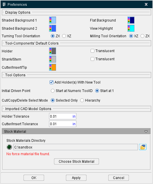
The Preferences command button opens the Preferences window, enabling you to control how information in the Tool Manager is displayed. The following picture shows the Tool Manager Preferences window when accessed from Tool Manager within Vericut.
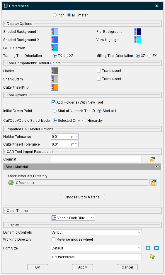
The following picture shows the Tool Manager Preferences window when accessed from stand-alone Tool Manager. Notice that there are a few additional features in the Display section at the bottom of the window.
📝 NOTE: All settings in the Tool Manager Preferences window are stored in the cgtech_toolman_80_user.prefs file.
Inch — Use to specify that the default units, for new tools created in Tool Manager, is Inch.
Millimeter — Use to specify that the default units, for new tools created in Tool Manager, is Millimeter.
Display Options group
Background Colors — Enables you to specify the background colors of the Tool Manager Tool Display area.
To change the background color, click on the  (Set Color) icon to display the color palette window shown below.
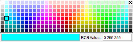
Click on a color in the color palette window, to specify the background color. The color palette window will close and the right side of the (Color Palette) icon in the Report Template window Menu ribbon will update to reflect the selected color.
To close the color palette window without changing the color, click on the  in the upper right corner of the color palette window.
Shaded Background 1 and 2 — Enables you to select colors that the background will transition between assuming you have set your view to Shaded background.
Flat Background — Enables you to select a single color for a non-shaded background assuming you have set your view to Flat background.
View Highlight — Enables you to specify the color of features when they are highlighted in the view window.
Turning Tool Orientation — Use to specify the default orientation of turning tools. Options are along the ZX axis or the XZ axis.
Milling Tool Orientation — Use to specify the default orientation of milling tools. Options are along the ZX axis or the XZ axis.
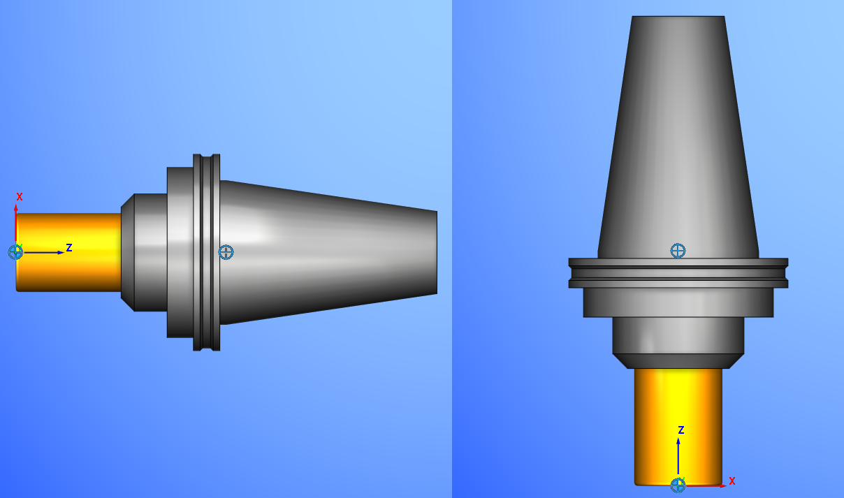
Example of a Milling Tool in XZ orientation (left) versus ZX orientation (right):
Tool-Components’ Default Colors group
Holder — Enables you to select the display color of Holders when the Inherit features is toggled on (checked). Toggle on (check) the Translucent option if you want holders to be see through.
Shank/Stem — Enables you to select the display color of Shanks when the Inherit features is toggled on (checked). Toggle on (check) the Translucent option if you want shanks to be see through.
Cutter/Insert/Tip — Enables you to select the display color of Cutters and Inserts when the Inherit feature is toggled on (checked).
Tool Options group
Add Holder(s) With New Tool — When toggled on (checked), this feature specifies that each new tool will be added with a Holder component. When toggled off (not checked) only a cutter component will be added to the new tool.
Initial Driven Point — Enables you to select between two choices (Start at Numeric ToolID and Start at 1).
-
Start at Numeric ToolID specifies that a Tool’s initial driven point will be named by their ToolID. Additional driven points will be named as described below for the Start at 1 option. The Start at Numeric ToolID feature only applies to numeric Tool IDs. Tools that have Alpha or Alphanumeric Tool IDs will be named as described below for the Start at 1 feature.
-
Start at 1 specifies that a Tool’s initial driven point will be named numerically starting with 1. Additional driven points will be named 2, 3, etc.
Cut/Copy/Delete Select Mode — Enables you to select between two choices (Selected Only and Hierarchy).
-
Selected Only specifies that when cutting, copying, or deleting, only the highlighted item will be cut, copied, or deleted.
-
Hierarchy specifies that when cutting, copying, or deleting, the highlighted item and all child components below it in the hierarchical structuring will be cut, copied, or deleted.
Imported CAD Model Options group
Holder Tolerance — Enables you to specify the Holder Tolerance by entering the tolerance value in the Holder Tolerance text field.
Cutter/Insert Tolerance — Enables you to specify the Cutter/Insert Tolerance by entering the tolerance value in the Cutter/Tolerance text field.
📝 NOTE: When specifying Holder Tolerance and Cutter/Insert Tolerance values, the specified values will be applied to Holder Tolerance and Cutter/Insert Tolerance in the Tool Manager Preferences window and the Import CAD Tool window.
Stock Material group
Stock Materials Directory — Use this field to set the filepath to reference Force Materials.
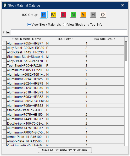
Choose From Catalog — Opens the Stock Material Catalog window.
Stock Material Catalog — This window enables you to search through all available material options for your stock materials. Use the ISO Group or Filter option at the top to find the Stock Material Name, Tool Material, or Tool Edge Type you are looking for. You can toggle between View Stock Materials and View Stock and Tool Info to see different levels of information about each material. Once you have highlighted your material, click Save As Optimize Stock Material to implement your selection.
📝 NOTE: The following features are only available when the Tool Manager Preferences window when accessed from stand-alone Tool Manager.