Drilling & Fastening Branch
Right-click on a Drilling & Fastening branch in the Project Tree panel to display the following menu:
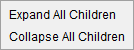
Expand All Children — Expands all branches below the Drilling & Fastening branch.
Collapse All Children — Collapses all branches below the Drilling & Fastening branch.
If the Configure icon is toggled "on", the Configure Drilling & Fastening menu displays at the bottom of the Project Tree.
Fastener Models branch
Right-click on a Fastener Models branch in the Project Tree panel to display the following menu:
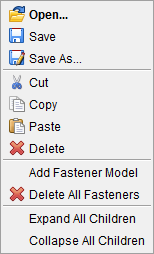
Open – Opens the Open File file selection window, enabling you to select the desired fastener model file.
Save – Opens the Save Fastener Model File file selection window, enabling you to save the fastener model file.
Save As – Opens the Save Fastener Model File file selection window, enabling you to save the fastener model file.
Cut — Cuts the highlighted fastener model from the Project Tree and puts it in the paste buffer.
Copy — Use to copy the highlighted fastener model to the paste buffer.
Paste — Use to paste the contents of the paste buffer to the Fastener Models branch. This enables you to copy one, or more, fastener models from one setup and paste them to the Fastener Models branch of another setup.
Delete – Use to delete the highlighted fastener model.
Add Fastener Model — Displays the Configure Fastener Model menu at the bottom of the Project Tree. The Configure icon at the top of the Project Tree must be toggled "on".
Delete All Fasteners — Use to delete all fastener models from the Fastener Models branch.
Expand All Children — Expands the Fastener Models branch to display all fastener models in the branch.
Collapse All Children — Collapses the fastener models under Fastener Models branch.
If the Configure icon is toggled "on", the Configure Fastener Model menu displays at the bottom of the Project Tree.
Fastener Model
Right-click on a Fastener Model in the Project Tree panel to display the following menu:
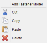
Add Fastener Model — Displays the Configure Fastener Model menu at the bottom of the Project Tree. The Configure icon at the top of the Project Tree must be toggled "on".
Cut — Cuts the highlighted fastener model from the Project Tree and puts it in the paste buffer.
Copy — Use to copy the highlighted fastener model to the paste buffer.
Paste — Use to paste the copied model to the current Fastener Models branch. VDAF will automatically assign a default ID to the copied model. The ID can be modified in the Configure Fastener Model menu.
Delete — Use to delete the highlighted fastener model.
If the Configure icon is toggled "on", the Configure Fastener Model menu displays at the bottom of the Project Tree.
Design Locations
Right-click on Design Locations in the Project Tree panel to display the following menu:
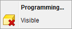
Programming — Starts the Vericut Fastener Programming application.
Visible — Use to turn on/off the display of the Design Locations data in the graphics area. The Visible icon will indicate the visibility status of the Design Locations data. ![]() indicates "visible",
indicates "visible", ![]() indicates "not visible". Click on Visible to toggle between the two modes. In the Project Tree, any coordinate system in the "not visible" state will be displayed in gray instead if a color.
indicates "not visible". Click on Visible to toggle between the two modes. In the Project Tree, any coordinate system in the "not visible" state will be displayed in gray instead if a color.
If the Configure icon is toggled "on", the Configure Design Locations menu displays at the bottom of the Project Tree.
Simulated Locations
Right-click on Simulated Locations in the Project Tree panel to display the following menu:
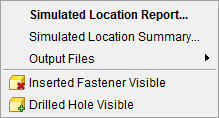
Simulated Location Report — Use to open the Simulated Location Report panel.
Simulated Location Summary — Use to open the Simulated Location Summary panel.
Output Files — Use to select the type of file that the Simulated Location Report will be generated as. Options include: XML, IGES, and Text.
Inserted Fastener Visible — Use to turn on/off the display of inserted fasteners in the graphics area. The Visible icon will indicate the visibility. ![]() indicates "visible",
indicates "visible", ![]() indicates "not visible". Click on Visible to toggle between the two modes. In the Project Tree, any coordinate system in the "not visible" state will be displayed in gray instead if a color.
indicates "not visible". Click on Visible to toggle between the two modes. In the Project Tree, any coordinate system in the "not visible" state will be displayed in gray instead if a color.
Drilled Hole Visible — Use to turn on/off the display of drilled holes in the graphics area. The Visible icon will indicate the visibility. ![]() indicates
"visible",
indicates
"visible", ![]() indicates "not visible". Click on Visible to toggle between the two modes. In the Project Tree, any coordinate system in the "not visible" state will be displayed in gray instead if a color.
indicates "not visible". Click on Visible to toggle between the two modes. In the Project Tree, any coordinate system in the "not visible" state will be displayed in gray instead if a color.
If the Configure icon is toggled "on", the Configure Simulated Locations menu displays at the bottom of the Project Tree.