Configure Collision menu
Location:
Project Tree > Collision branch (Configure “on”)
The features on the Configure Collision menu enable you to turn on Machine Collision Detection and to specify the Tool to Stock/Fixture collision conditions that you want Vericut to check during processing.
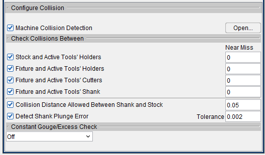
Machine Collision Detection — Use to turn Machine Collision Detection “On” and “Off”. When toggled "On" (checked), detects collisions between components specified in the Collision and Travel Limits window, Collision Detect tab.
- Open — Displays the Collision and Travel Limits window, Collision Detect tab enabling you to control when collisions between machine components are detected, which components are protected, and specify the tolerances used for detecting collisions.
Stock and Active Tools’ Holders — When toggled “on” (checked), Vericut will check for collisions between the “active” tool’s holder components and any visible stock components during processing.
- Near Miss — Use to specify a value that controls how close two components are permitted to get to each other before a collision is reported. Enter a positive value to be alerted if components come near each other within the specified clearance distance, zero to indicate that the two components may not touch. A negative value is treated like zero.
📝 NOTE: When toggled “on” (checked) the above settings will override Stock/Tool records in the Collision and Travel Limits window (Project Tree: Collision branch right mouse button menu > Open) and Stock/Tool and Tool/Stock records in the Machine Settings window (Configuration tab > Machine Settings).
See Collision and Travel Limits window, Collision Detect tab section of Vericut Help for additional information.
Also see Machine Settings window: Collision Detect tab in the Configuration tab section of Vericut Help.
Fixture and Active Tools’ Holders — When toggled “on” (checked), Vericut will check for collisions between the “active” tool’s holder components and any visible fixture components during processing.
- Near Miss — Use to specify a value that controls how close two components are permitted to get to each other before a collision is reported. Enter a positive value to be alerted if components come near each other within the specified clearance distance, zero to indicate that the two components may not touch. A negative value is treated like zero.
📝 NOTE: When toggled “on” (checked) the above settings will override Fixture/Tool records in the Collision and Travel Limits window (Project Tree: Collision branch right mouse button menu > Open) and Fixture/Tool and Tool/Fixture records in the Machine Settings window (Configuration tab > Machine Settings).
See Collision and Travel Limits window, Collision Detect tab section of Vericut Help for additional information.
Also see Machine Settings window: Collision Detect tab in the Configuration tab section of Vericut Help.
Fixture and Active Tools’ Cutters — When toggled “on” (checked), Vericut will check for collisions between the “active” tool’s cutter components and any visible fixture components during processing.
- Near Miss — Use to specify a value that controls how close two components are permitted to get to each other before a collision is reported. Enter a positive value to be alerted if components come near each other within the specified clearance distance, zero to indicate that the two components may not touch. A negative value is treated like zero.
📝 NOTE: When toggled “on” (checked) the above settings will override Fixture/Tool records in the Collision and Travel Limits window (Project Tree: Collision branch right mouse button menu > Open) and Fixture/Tool and Tool/Fixture records in the Machine Settings window (Configuration tab > Machine Settings).
See Collision and Travel Limits window, Collision Detect tab, also in the Project Tree section of Vericut Help for additional information.
Also see Machine Settings window: Collision Detect tab in the Configuration tab section of Vericut Help.
Fixture and Active Tools’ Shank — When toggled “on” (checked), Vericut will check for collisions between the “active” tool’s shank components and any visible fixture components during processing.
Collision Distance Allowed Between Shank and Stock — When toggled “on” (checked), Vericut will check for collisions between the non-cutting shank portion of the tool, and Stock components during processing. A corresponding “distance” value of “0” causes all Shank errors detected by Vericut to be reported. To small shank errors that are considered insignificant, enter a positive number that specifies the allowable distance (thickness) that shanks are allowed to collide with Stock. Vericut will only report errors for shanks involved in collisions having collision distances greater than the specified amount.
Detect Shank Plunge Error — When toggled on (on by default), Vericut outputs “Plunge” errors for Hole Making tools that plunge (via motion along their tool axis) deeper into stock material than their defined Flute Lengths.
- Tolerance — Shank Plunge Error Tolerance is the vertical distance along the tool’s axis which is shank allowed to go into the drilled hole. The value can be “0” or a positive number. Shank Plunge Error Tolerance is not applied as a side-wise distance from the shank diameter, to the cylindrical surface of the hole.
Constant Gouge/Excess Check — Enables you to specify a maximum gouge value, and a minimum excess value, and turn Constant Gouge Check on and off. Gouge areas found by Constant Gouge Check during NC Program processing are displayed in the assigned Error color.
-
Off — Turns Constant Gouge Check off.
-
Maximum Allowable Gouge — Select Maximum Allowable Gouge from the pull-down list and enter the value in the text field. Then select Apply to turn Constant Gouge Check on.
-
Minimum Allowable Excess — Select Minimum Allowable Excess from the pull-down list and enter the value in the text field. Then select Apply to turn Constant Gouge Check on.
Constant Gouge/Excess Check can be toggled On/Off at any time during the simulation.
📝 NOTES: A design model must be present in the component tree for Constant Gouge Check to detect potential gouges.
See Collision Branch section of Vericut Help, for information on specifying the collision conditions between machine components that you want Vericut to check during processing.
The sequence of events that takes place when a collision is detected is dependent on how the Animation Speed Slider is set and whether Stop at Max Errors is toggled "On" or "Off". See What Happens When a Collision is Detected? section of Vericut Help for complete information.