Coordinate Systems Branch
Right-click on a Coordinate Systems branch in the Project Tree panel to display the following menu:
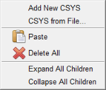
Add New CSYS — Adds a new CSYS to the Coordinate Systems branch in the Project Tree. Vericut automatically provides a unique name for the CSYS. You can right-click on the default name and select Rename from the menu that displays to rename the CSYS if desired.
New coordinate systems are created with zero translation and rotation values and attached to the Base component. The newly added coordinate system is automatically selected in the Project Tree. If the Configure icon is toggled “on”, the Configure Coordinate System menu automatically displays at the bottom of the Project Tree enabling you to make any necessary modifications to the newly added CSYS.
CSYS from File — Displays a file selection box enabling you to specify the CSYS file to be used.
The Create CSYS While Simulating feature, in the Configure Coordinate System menu, must be toggled “off” (not checked) when using CSYS from File. This functionality is also available via the csys_file command line option.
See CSYS File in the Getting Started section of Vericut Help for information on CSYS file formats.
Paste — Use to paste the contents of the paste buffer to the Coordinate Systems branch.
Delete All — Deletes all coordinate systems from the Coordinate System branch.
Expand All Children — Expands the Coordinate System branch showing all coordinate systems available in the setup.
Collapse All Children — Collapses the Coordinate System branch.
If the Configure icon is toggled “on”, the Configure Coordinate System menu displays at the bottom of the Project Tree.
Coordinate System
Right-click on a Coordinate System in the Project Tree panel to display the following menu:
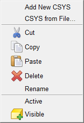
Add New CSYS — Adds a new CSYS to the Coordinate Systems branch in the Project Tree. Vericut automatically provides a unique name for the CSYS. You can right-click on the default name and select Rename from the menu that displays to rename the CSYS if desired.
New coordinate systems are created with zero translation and rotation values and attached to the Base component. The newly added coordinate system is automatically selected in the Project Tree. If the Configure icon is toggled “on”, the Configure Coordinate System menu automatically displays at the bottom of the Project Tree enabling you to make any necessary modifications to the newly added CSYS.
CSYS from File — Displays a file selection box enabling you to specify the CSYS file to be used.
The Create CSYS While Simulating feature, in the Configure Coordinate System menu, must be toggled “off” (not checked) when using CSYS from File. This functionality is also available via the csys_file command line option.
See CSYS File in the Getting Started section of Vericut Help for information on CSYS file formats.
Cut — Cuts the highlighted coordinate system from the Project Tree and puts it in the paste buffer.
Copy — Copies the highlighted coordinate system from the Project Tree to the paste buffer.
Paste — Adds the contents of the paste buffer after the highlighted coordinate system in the Project Tree.
Delete — Deletes the highlighted model from the Project Tree.
Rename — Use to rename the highlighted coordinate system.
Active — Displays a list of all available coordinate systems enabling you to set the active coordinate system. A check indicates the active coordinate system.
Visible — Use to make the highlighted coordinate system visible, or not visible in the Vericut graphics area. The Visible icon will indicate the visibility status of the coordinate system. ![]() indicates "visible",
indicates "visible", ![]() indicates "not visible". Click on Visible to toggle between the two modes. In the Project Tree, any coordinate system in the "not visible" state will be displayed in gray instead if a color.
indicates "not visible". Click on Visible to toggle between the two modes. In the Project Tree, any coordinate system in the "not visible" state will be displayed in gray instead if a color.
If the Configure icon is toggled “on”, the Configure Coordinate System menu displays at the bottom of the Project Tree.