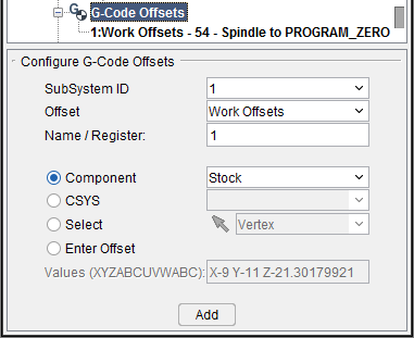
Configure G-Code Offsets menu
Location:
Project Tree > G-Code Offsets branch (Configure “on”)
The features on the Configure G-Code Offsets menu enable you to add a new G-Code Offsets table to the Project Tree. G-Code Offset tables are used to store work offsets or shift offsets specific to the NC program file(s) in the current setup. These G-Code Offsets tables are stored in the Project file (.vcproject, .vcsproject, .vdafproject) and will override those stored in the Machine file. All of the following features are also available on the Configure Work Offsets and are described in detail in the next section.
SubSystem ID — Use to specify ID of the machine subsystem for which the table is being defined.
Offset — Use to identify the type of offset table to be added, or modified, if it already exists. Choose one of the following offset table types from the pull-down list.
-
Base Work Offset — The Base Work Offset table specifies the location from which work offsets are based. Use this table when the NC program file references a base work coordinate system (e.g. G52) from which all other work offsets are based..
-
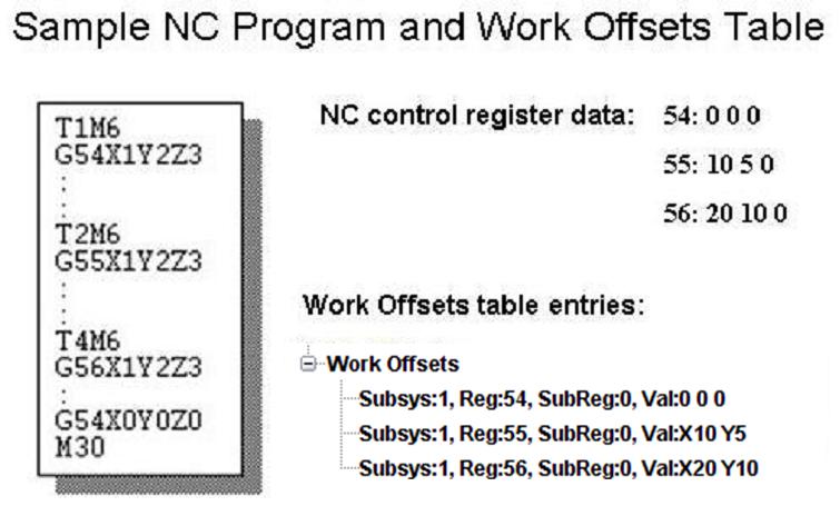
Work Offsets — The Work Offsets table stores work coordinate system offset, or "fixture offset" values. Use this table when simulating programming with work offsets (e.g. G53-59). Enter values to represent the work offset values entered at the NC control. Work coordinate system offset values that are automatically loaded using data in the NC program file (e.g. G10L2Pn) do not require entry.
-
Shift Offsets — The Shift Offsets table stores work coordinate system offsets similar to Work Offsets.
-
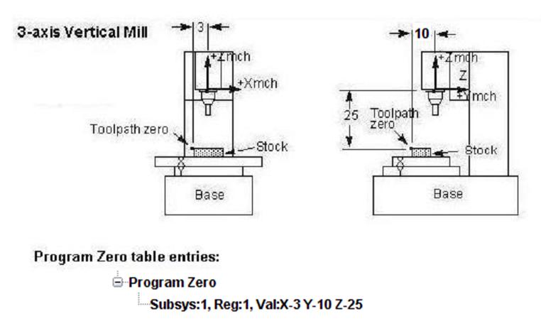
Program Zero — The Program Zero table is used to specify the programmed zero location of a G-Code NC program file taking Tool Length Compensation into consideration. This table is required when the machine operator establishes a zero location other than machine zero. This activity is also known as establishing a "floating zero" location.
Name/Register — The name or Register number that will be used by Vericut to access corresponding table data. The Register number may correspond to an offset register number, or an integer value, as required by a particular table. The user can enters text similar to what is defined in the NC program. It could be G54, G54.2P5, G500, or just a register number.
📝 NOTE: Vericut knows what G54/G54.2P5 stand for (work offset and secondary work offset) and it will automatically define the table based on what is define in the control file.
📝 NOTE: The user can still enter just the Register number.
The following features are mutually exclusive selections that can be toggled between to place your G-Code Offsets.
Component — Use this field to specify which component your G-Code Offset will be associated with. Example components include Stock, Fixtures, and so on.
CSYS — Use this field to associate your G-Code Offset with an active coordinate system.
Select — Select this toggle to associate your G-Code Offset by manually clicking in the Graphics Display Area. Click the ![]() icon to enable mouse selection. Use the dropdown menu to select which features the mouse click will associate the G-Code Offset to. Potential examples include Vertex, Circle Center, 3 Planes, CSYS Origin, Component Origin, and Model Origin.
icon to enable mouse selection. Use the dropdown menu to select which features the mouse click will associate the G-Code Offset to. Potential examples include Vertex, Circle Center, 3 Planes, CSYS Origin, Component Origin, and Model Origin.
Enter Offset — Use this field to manually enter the X Y Z values you want the G-Code Offset associated with.
Add — this button is used to introduce a new offset table to the Project Tree with a default table record highlighted. The Configure Work Offsets menu is automatically displayed enabling you to specify values for the record. If the offset table of the same type already exists, an error message is output.
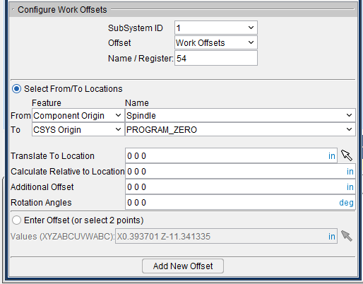
Configure Work Offsets
Location:
Project Tree > Work Offsets (Configure “on”)
The features on the Configure Work Offsets menu enable you to specify values for G-Code Work Offsets. Vericut offsets enable the position of a simulated machine’s axes to be adjusted by a specified distance in order to position the tool at the correct location commanded in the NC program.
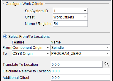
Vericut provides two ways to enter table values. Select From/To Locations method enables the NC Part Programmer to select a “From” reference feature on his virtual machine’s “tool side” of the kinematic stack, and a “To” reference feature on the “part side” of the kinematic stack, and Vericut automatically calculates each axis’ offset value. The Select From/To Locations method values will automatically be updated if the machine configuration or the location of the CSYS origin changes.
You can also use the Enter Offset method to specify the offset directly by selecting two points in the graphics display area and have Vericut will calculate the Offset values between the selected points, or by entering specific offset amounts to be assigned to each axis. The Enter Offset method does not automatically update the values when there are changes in the machine’s configuration or the location of the CSYS origin. This method emulates how offsets are set and used in CNC controls.
Features SubSystem ID, Offset, and Name/Register (shown in the G-Code Offset table) are highlighted in the Project Tree, which the table record is associated with. These features are described in the Configure G-Code Offsets menu section.
Select From/To Locations — Enables you to specify table values based on a "relational" offset between a "from" point and a "to" point. The "from" and "to" points are designated by specifying a particular component or CSYS. Vericut will use the origin of the component/CSYS as the point. You can also specify an offset from the specified component/CSYS origin point. Once this relationship has been established, you can change the machine configuration or the location of the CSYS origin and the table values will updated automatically during the initial Single Step or during Play to End.
For example: After Input Program Zero has been defined to be the offset from the Tool Component to the "Program Zero" CSYS, you can change the machine configuration, or change the location of "Program Zero" CSYS, and the Input Program Zero offset values will be updated automatically during the initial Single Step or during Play to End.
📝 NOTE: The offsets are calculated based on where the corresponding origin points are located when all linear axes are driven to machine zero (zero with no offsets in place).
Select From/To Locations section
When Select From/To Locations is toggled "On", the From/To Feature/Name lists and the Offset text fields become activated. Use the From/To Feature lists to specify whether the point is associated with a Component or a CSYS (coordinate system). Use the From/To Name lists to specify a specific component or coordinate system.
📝 NOTE: Only the coordinate systems that have been defined with reference to a machine component (i.e., visible in a Machine view when Coordinate System axis is toggled "on") will appear in the CSYS/Names lists. See the discussion for Project tab > Active Coordinate Systems for more information on Vericut Coordinate Systems.
Translate To Location — Use this text field to enter 3 values, separated by spaces, representing the X, Y, and Z offset from the specified origin point. You can also click on the "select" button ![]() , then pick a point in the graphics display area. You can pick the point in either a workpiece or machine view. Vericut will calculate the Translate To Location value between the selected point and the designated origin point.
, then pick a point in the graphics display area. You can pick the point in either a workpiece or machine view. Vericut will calculate the Translate To Location value between the selected point and the designated origin point.
Calculate Relative to Location — This feature enables you to have a relational offset recalculated in the machine position where the offset will be used. The new position is immediately calculated and stored and therefore is not dependent on the machine position when the offset is activated.
Additional Offset — Use this text field to specify an additional offset value.
Rotation Angles — Use this text field to enter 3 values separated by spaces, representing the X, Y, and Z degrees of offset in terms of rotation.
Select From/To Locations Example:
In this example the offset is calculated by measuring from the Spindle component to a coordinate system at the part program origin:
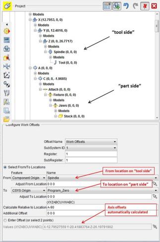
In the above example the “spindle” component is a special component that is automatically adjusted when a tool is mounted in the spindle. The distance from the spindle origin to the driven point on the tool is automatically added to the offset calculation. Of course the values change with each tool change.
Both the From and To choices provide options to support a large variety of NC programming styles. Today most NC programs are designed to position the tool’s “tip” at the coordinate locations in the NC program. And the coordinate locations are relative to the workpiece being machined. However, some companies with 5-axis machines choose to program from the intersection of rotary axes on the tool-side. And some choose to reference a location on a fixture rather than the workpiece on the part-side. The Select From/To Locations method is flexible enough to adapt to many different needs of many different Vericut users.
The Select From/To Locations method also sets-up a relationship between the tool-side component and the part-side component. This is useful when the reference frame of the NC program changes during the middle of the program. This programming technique is often used in Siemens 840D controls. It is also implied when different heads with additional axes or other orientations are mounted on the machine in the middle of the NC program.
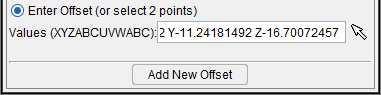
Enter Offset section
Enter Offset (or select 2 points) — when toggled "On", the Values (XYZABCUVWABC) text field is activated enabling you to enter one to twelve numeric values as required by the specific table. Multiple value entries require spaces between the values.
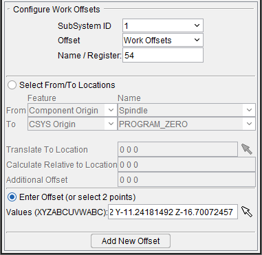
In the sample window shown above, the current table is the Work Offsets table. The current table entry is register "54", and contains the values "-17 -8 -16.5". The table is applicable to subsystem "1" of the machine.
Vericut supports two ways to input values into these tables from the G-Code Table Record menu. Both use the Values (XYZABCUVWABC) text field, but use a different syntax):
Traditional format: values are entered in the order specified (XYZABCUVWABC) and are separated by spaces.
WORD/VALUE format: (X10 C45)
In either case, the resulting display of the axis values will be in the WORD/VALUE format. Only non-zero values will be displayed. In the case of all zero's, X0 Y0 Z0 will be displayed.
The WORD/VALUE format has the following rules:
-
Valid Words are: X, Y, Z, A, B, C, U, V, W, AA, BB, CC
-
Mixed formats are not allowed. You can use either the Traditional format or the WORD/VALUE format.
- The Words can be entered in any order.
- You only need to specify words with non-zero values.
- If a word is specified twice, the last value specified will be used.
- If all values are zero, you can leave the field blank. In this case, the display will be X0 Y0 Z0.
You can also click on the "select" button ![]() , then pick two points in the graphics display area. You can pick the points in either a workpiece or machine view. Vericut will calculate the Offset value between the selected points.
, then pick two points in the graphics display area. You can pick the points in either a workpiece or machine view. Vericut will calculate the Offset value between the selected points.
Add New Offset — Click this button to go back to the Configure G-Code Offsets menu, enabling you to create a new G-Code Offset.
The following sections describe the specific Values (XYZABCUVWABC) text field values associated with each G-Code Offsets table type.
Base Work Offset table
Use one of the following methods to define the Base Work Offset:
-
Specify table values based on a "relational" offset between a "from" point and a "to" point. The "from" and "to" points are designated by specifying a particular component or CSYS.
-
Enter values representing the base work offset, as entered at the NC control, in the Values (XYZABCUVWABC): text field.
Values (XYZABCUVWABC): Xval Yval Zval Aval Bval Cval Uval Vval Wval Aval Bval Cval where linear offset values Xval-Zval and Uval-Wval are measured in the machine coordinate system from machine zero. Rotary offset values Aval-Cval are measured from the corresponding rotary component zero and are expressed in decimal degrees. Enter "0" for axes that do not have a base work offset or do not exist in the machine. Zero is assumed for unspecified machine axis offsets.
The examples that follow show table entry formats for various NC machine configurations.
| Machine configuration | Table entry format |
|---|---|
| 3 axes - XYZ | Xval Yval Zval 0 0 0 0 0 0 0 0 0 or 1: Xval Yval Zval ("0" assumed for axes A B C U V W A B C) |
| 4 axes - XYZA | Xval Yval Zval Aval |
| 4 axes - XYZB | Xval Yval Zval 0 Bval |
| 4 axes - XYZC | Xval Yval Zval 0 0 Cval |
| 4 axes - XZUW | Xval 0 Zval 0 0 0 Uval 0 Wval |
| 5 axes - XYZAB | Xval Yval Zval Aval Bval |
| 5 axes - XYZAC | Xval Yval Zval Aval 0 Cval |
| 5 axes - XYZBC | Xval Yval Zval 0 Bval Cval |
| 9 axes - XYZABCUVW | Xval Yval Zval Aval Bval Cval Uval Vval Wval |
You can also click on the "select" button, ![]() then pick two points in the graphics display area. You can pick the points in either a Workpiece or Machine view. Vericut will calculate the Offset value between the selected points.
then pick two points in the graphics display area. You can pick the points in either a Workpiece or Machine view. Vericut will calculate the Offset value between the selected points.
Work Offsets/Shift Offsets table
Use one of the following methods to define the Work Offset or Shift Offset:
-
Specify table values based on a "relational" offset between a "from" point and a "to" point. The "from" and "to" points are designated by specifying a particular component or CSYS.
-
Enter values representing the work offset, as entered at the NC control, in the Values (XYZABCUVWABC): text field.
Values (XYZABCUVWABC): Xval Yval Zval Aval Bval Cval Uval Vval Wval Aval Bval Cval where linear offset values Xval-Zval and Uval-Wval are measured in the machine coordinate system from machine zero. Rotary offset values Aval-Cval are measured from the corresponding rotary component zero and are expressed in decimal degrees. Enter "0" for axes that do not have a base work offset or do not exist in the machine. Zero is assumed for unspecified machine axis offsets.
Enter offset values for each local work coordinate system referenced by the NC program. The figure below shows a sample table to support an NC program file which references work offsets: G54, 55, 56.
The examples that follow show general table entry formats for various NC machine configurations.
| Machine configuration | Table entry format |
|---|---|
| 3 axes - XYZ | Xval Yval Zval 0 0 0 0 0 0 0 0 0 or Xval Yval Zval ("0" assumed for axes A B C U V W A B C) |
| 4 axes - XYZA | Xval Yval Zval Aval |
| 4 axes - XYZB | Xval Yval Zval 0 Bval |
| 4 axes - XYZC | Xval Yval Zval 0 0 Cval |
| 4 axes - XZUW | Xval 0 Zval 0 0 0 Uval 0 Wval |
| 5 axes - XYZAB | Xval Yval Zval Aval Bval |
| 5 axes - XYZAC | Xval Yval Zval Aval 0 Cval |
| 5 axes - XYZBC | Xval Yval Zval 0 Bval Cval |
| 9 axes - XYZABCUVW | Xval Yval Zval Aval Bval Cval Uval Vval Wval |
You can also click on the "select" button, ![]() then pick two points in the graphics display area. You can pick the points in either a Workpiece or Machine view. Vericut will calculate the Offset value between the selected points.
then pick two points in the graphics display area. You can pick the points in either a Workpiece or Machine view. Vericut will calculate the Offset value between the selected points.
📝 NOTES:
-
To specify an initial work offset to be in effect, use the features on the Offsets panel (Project tab > Offsets).
-
When a Base Work Offset table is in use, work offsets are established from the base work offset location (method commonly used by Phillips CNC controls).
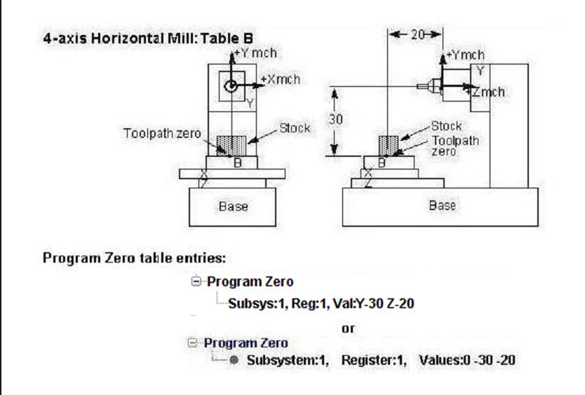
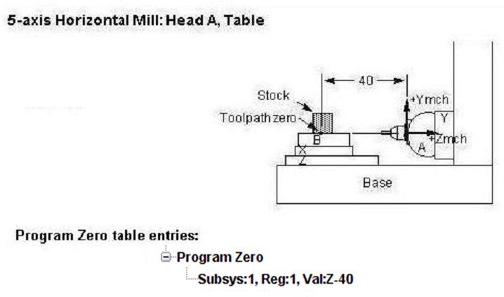
Program Zero table
Use one of the following methods to define the Program Zero:
-
Specify table values based on a "relational" offset between a "from" point and a "to" point. The "from" and "to" points are designated by specifying a particular component or CSYS.
-
Enter values representing the Program Zero, as entered at the NC control, in the Values (XYZABCUVWABC): text field.
Values (XYZABCUVWABC): Xval Yval Zval Aval Bval Cval Uval Vval Wval Aval Bval Cval where linear offset values Xval-Zval and Uval-Wval are measured in the machine coordinate system from machine zero. Rotary offset values Aval-Cval are measured from the corresponding rotary component zero and are expressed in decimal degrees. Enter "0" for axes that do not have a base work offset or do not exist in the machine. Zero is assumed for unspecified machine axis offsets.
You can also click on the "select" button, ![]() then pick two points in the graphics display area. You can pick the points in either a Workpiece or Machine view. Vericut will calculate the Offset value between the selected points.
then pick two points in the graphics display area. You can pick the points in either a Workpiece or Machine view. Vericut will calculate the Offset value between the selected points.
Values for this table are calculated differently, depending on the programming method used by the NC program file. Each programming method is listed below with an example of how the Program Zero table values are calculated for that method.
-
With Tool Tip programming method- calculate values from the Machine reference point with no offsets in effect, such as: cutter compensation, work offsets, etc.
-
With Gage Length programming method- calculate values from the Machine reference point with no offsets in effect, such as: cutter compensation, work offsets, etc.
- With Tool Length Compensation programming method- calculate values from the Machine reference point to the programmed zero when tool length compensation is active (e.g. G43).
📝 NOTE: The Program Zero Table is intended to replace the use of the Input Program Zero/Input Program Zero (Special Z) table. While very similar in most respects, it does a much better job of handling Tool Length Compensation.
The figures that follow show sample table entries which specify the programmed zero location of NC program files run on various NC machine configurations.
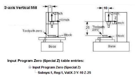
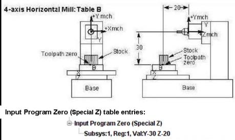
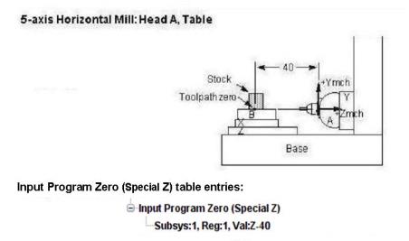
Input Program Zero (Special Z) table
Use one of the following methods to define the Input Program Zero (Special Z):
-
Specify table values based on a "relational" offset between a "from" point and a "to" point. The "from" and "to" points are designated by specifying a particular component or CSYS.
-
Enter values representing the Input Program Zero (Special), as entered at the NC control, in the Values (XYZABCUVWABC): text field.
Values (XYZABCUVWABC): Xval Yval Zval Aval Bval Cval Uval Vval Wval Aval Bval Cval where linear offset values Xval-Zval and Uval-Wval are measured in the machine coordinate system from machine zero. Rotary offset values Aval-Cval are measured from the corresponding rotary component zero and are expressed in decimal degrees. Enter "0" for axes that do not have a base work offset or do not exist in the machine. Zero is assumed for unspecified machine axis offsets.
You can also click on the "select" button, ![]() then pick two points in the graphics display area. You can pick the points in either a Workpiece or Machine view. Vericut will calculate the Offset value between the selected points.
then pick two points in the graphics display area. You can pick the points in either a Workpiece or Machine view. Vericut will calculate the Offset value between the selected points.
Values for this table are calculated differently, based on the programming method used by the NC program file. Each programming method is listed below with an example of how Input Program Zero (Special Z)/Input Program Zero table values are calculated for that method.
-
With Tool Tip programming method- calculate values from the Machine reference point with no offsets in effect, such as: cutter compensation, work offsets, etc.
-
With Gage Length programming method- calculate values from the Machine reference point with no offsets in effect, such as: cutter compensation, work offsets, etc.
- With Tool Length Compensation programming method- calculate values from the Machine reference point to the programmed zero when tool length compensation is active (e.g. G43).
The figures that follow show sample table entries which specify the programmed zero location of NC program files run on various NC machine configurations.
RTCP Pivot Offset table
Use one of the following methods to define the Program Zero:
-
Specify table values based on a "relational" offset between a "from" point and a "to" point. The "from" and "to" points are designated by specifying a particular component or CSYS.
-
Enter values representing the RTCP Pivot Offset, as entered at the NC control, in the Values (XYZ): text field.
Values (XYZ): Xval Yval Zval where Xval-Zval are calculated by subtracting the location of the Tool component origin from the rotary pivot point location, with all axes at their initial machine location. Enter "0" for axes that do not have an offset or do not exist in the machine. Zero is assumed for unspecified offsets.
You can also click on the "select" button, ![]() then pick two points in the graphics display area. You can pick the points in either a Workpiece or Machine view. Vericut will calculate the Offset value between the selected points.
then pick two points in the graphics display area. You can pick the points in either a Workpiece or Machine view. Vericut will calculate the Offset value between the selected points.
Examples of when to use this table:
-
RTCP is desired with a vertical 5-axis tilting head machine that has a pivot length of 10 and a B-axis initial location of 180. This configuration puts the tool axis in a vertical orientation. For calculations, the location of the pivot point can be assumed to be at (0 0 0). This would require RTCP Pivot Offset table values: 0 0 10. ((0 0 0) - (0 0 -10)) = (0 0 10)
-
If the B-axis initial location was 0 (tool axis in a vertical orientation), then the RTCP Pivot Offset table is not needed. However, if the table was to be defined, it should contain the values: 0 0 10. ((0 0 0) - (0 0 -10)) = (0 0 10)
This table can also be used to support a machine/control where the post-processor takes care of the offset for the pivot length, and the control handles the offset for each tool's gage length. For this situation, set RTCP Pivot Offset table values to: 0 0 0.
RPCP Pivot Offset table
Use one of the following methods to define the Program Zero:
-
Specify table values based on a "relational" offset between a "from" point and a "to" point. The "from" and "to" points are designated by specifying a particular component or CSYS.
-
Enter values representing the RPCP Pivot Offset, as entered at the NC control, in the Values (XYZ): text field.
Values (XYZ): Xval Yval Zval where Xval-Zval are calculated by subtracting the location of the Stock component origin from the rotary pivot point location, with all axes at their initial machine location. Enter "0" for axes that do not have an offset or do not exist in the machine. Zero is assumed for unspecified offsets.
You can also click on the "select" button, ![]() then pick two points in the graphics display area. You can pick the points in either a Workpiece or Machine view. Vericut will calculate the Offset value between the selected points.
then pick two points in the graphics display area. You can pick the points in either a Workpiece or Machine view. Vericut will calculate the Offset value between the selected points.
Adding, Modifying, or Deleting G-Code Offsets Tables
To add a new G-Code Offsets table:
-
In the Project tab, click Offsets > G-Code Offsets.
-
In the Offsets: G-Code panel , select the desired table type from the Offset Name pull-down list.
- Select the SubSystem ID from the pull-down list for the table data that is being defined.
- Select the Offset subtype from the pull-down list.
- Enter the Name/Register value.
- Select Component , CSYS , Select , or Enter Offset.
- Click on the Add button.
OR
-
In the Project Tree, click on the G-Code Offsets branch.
-
In the Configure G-Code Offsets menu at the bottom of the Project Tree , select the desired table type from the Offset Name pull-down list.
- Select the SubSystem ID from the pull-down list for the table data that is being defined.
- If you are creating a G-Code Offsets table other than a Base Work Offset or Machine Zero table, enter the Register value.
- If you are creating a Work Offsets or Shift Offsets table, enter the SubRegister value.
- Click on the Add button to add the table to the Tables List. Notice that the selected table and a default table record have been added to the Tables List.
-
Use one of the following methods to enter G-Code Offsets Table record values.
Use Select From/To Locations to create a “relational” offset that will automatically be updated if the machine configuration or the location of the CSYS origin changes.
You can also use Enter Offset (or select 2 points) to specify the offset directly by selecting two points in the graphics area, or entering axis values in the Values (XYZABCUVWABC): text field. This method does not automatically update.
See Configure G-Code Offsets Table Record menu section of Vericut Help for table specific information. -
Press Enter to update the table record.
Add an additional table record:
-
In the Project Tree, click on the G-Code Offsets table, in the Tables List, that you want to add an additional table record to.
-
Select the SubSystem ID from the pull-down list for the table record that you are adding.
- If you are adding an additional table record to any G-Code Offsets table other than a Base Work Offset or Machine Zero table, enter the Register value.
- If you are adding an additional table record to a Work Offsets or Shift Offsets table, enter the SubRegister value.
- Click on the Add button to add an additional default table record to the Tables List.
-
Use one of the following methods to enter G-Code Offsets Table record values.
Use Locations to create a “relational” offset that will automatically be updated if the machine configuration or the location of the CSYS origin changes.
You can also use Enter Offset (or select 2 points) to specify the offset directly by selecting two points in the graphics area, or entering axis values in the Values (XYZABCUVWABC): text field. This method does not automatically update.
See Configure Work Offsets menu section of Vericut Help for table specific information. -
Press Enter to update the table record.
To modify an existing table record:
- In the Project Tree, click on the table record, in the Tables List, that you want to modify.
-
Use one of the following methods to enter G-Code Offsets Table record values.
Use Select From/To Locations to create a “relational” offset that will automatically be updated if the machine configuration or the location of the CSYS origin changes.
You can also use Enter Offset (or select 2 points) to specify the offset directly by selecting two points in the graphics area, or entering axis values in the Values (XYZABCUVWABC): text field. This method does not automatically update.
See Configure Work Offsets menu section of Vericut Help for table specific information. -
Press Enter to update the table record.
To delete a table record from the Table list:
In the Project Tree, right click on the table record, in the Tables List, that you want to delete and then click on the Delete button that displays to delete the table record.
OR
In the Offsets: G-Code panel , right click on the desired offset and then click on the Delete button that displays.
To delete a table from the Table list:
In the Project Tree, right click on the table, in the Tables List that you want to delete and then click on the Delete button that displays to delete the table record. All table records associated with the deleted table are also deleted.