Stock
Delete Detached Stock (Delete Detached Stock window)
Location:
Project tab >  (Delete Detached Stock)
Toolbar short cut: ![]()
The Delete Detached Stock command button opens the Delete Detached Stock window enabling you to delete or keep pieces of material. This feature is typically used to delete pieces of excess stock that have been cut free from the workpiece. However, pieces of other models can also be deleted.
| Select Stock to Delete/Keep | Select Tab to Remove |
|---|---|
 |
 |
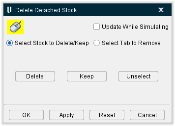
Select Stock to Delete/Keep — Items are selected for Delete/Keep in the Workpiece View. Any number of items can be selected. Selected items are immediately highlighted with the Error color. Once you click Delete (or Keep) the items are removed from all views. However, the selected items are not actually deleted until you click OK.
📝 NOTE: Once model pieces are deleted, model pieces cannot be restored.
 (Down to enable mouse tracking and picks, up to disable.) — Use this icon to designate that the Delete Detached Stock window is the window that picks in the Vericut graphics area are to be applied to. When toggled “on”, the icon is displayed in the Mouse Pick Highlight Color specified in the Configuration tab > Preferences window.
Update While Simulating — When toggled "On", Vericut checks during the simulation for detached material based on the stock's relationship to all parent fixture models. The Stock must be a Child of a Fixture component. See the picture below.
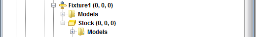
If the detached stock does not intersect, or is not tangent to, a parent fixture model, then the piece is considered "unattached" and is automatically deleted. This logic applies to both milling and turning operations.
For turning mode (when the stock is spinning), Vericut checks at the end of each block. For milling mode (when the tool is spinning), Vericut checks at each tool change, at the end of each file, whenever Vericut is stopped (except for "single step"), at Clamp/Unclamp events, and whenever the CheckForLooseMaterial macro is called. See the example in the next section.
If cut stock becomes unclamped (not in contact with any parent fixture models), Vericut may generate the message "Cut Stock was unclamped and is temporarily saved in Unclamped Stock". If this happens, the unclamped Cut Stock model can be recovered from the Unclamped Stock temporary component that was created for it (e.g. in the Project Tree, toggle “Show Machine Components” On, then expand Unclamped Stock located under the Base component.)
To prevent Cut Stock from becoming unclamped, you can add or modify fixture models to ensure contact with the Cut Stock, or turn the “Update While Simulating” option off in the Delete Detached Stock window.
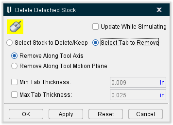
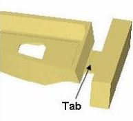
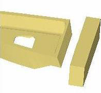
Select Tab to Remove — Use this feature to remove tabs left on the machined part (used for holding the part during the machining process) from a Vericut cut model. Vericut will project the cutter used to cut the selected machined surface, through the bottom of the part, removing the tab area. More than one position on the machined surface may need to be selected to remove the entire tab area. You can also use Min Tab Thickness and Max Tab Thickness options to ensure that no tabs beside the specific size tab you want to remove will be removed.
| Before Using Tab Removal | After Using Tab Removal | |
|---|---|---|
 |
 |
Remove Along Tool Axis — this default option removes tabs along the axis of the current tool.
*Remove Along Tool Motion Plane — *this option removes tabs along the motion plane.
Delete — After selecting the items to be deleted (they will be highlighted), click Delete to remove selected items from all views. Click OK, described above, to permanently delete the items.
You can also use Delete to delete the un-displayed portion of a sectioned view. Without selecting any items, click on Delete. You will be prompted with the message "The cut stock is sectioned. Delete the sectioned (invisible) material?" Yes/No". A "Yes" response permanently deletes all un-displayed (invisible) sectioned material. A "No" response does not. Using the Keep in this manner will produce the same results.
Keep — After selecting the items to keep (they will be highlighted), click Keep to remove all un-selected items (not highlighted) from all views. Click OK, described above, to permanently delete the items.
Unselect — Use this feature any time while selecting items for Delete/Keep to un-select all selected items (they will no longer be highlighted). This feature becomes inactive once you click on Delete/Keep.
OK — Use this feature to permanently delete the items selected for Delete/Keep, or activate Update while Simulating and close the Delete Material window.
Apply — Permanently deletes the stock without closing the window.
Reset — Puts the deleted stock back in place so long as OK or Apply have not been clicked. Clicking OK or Apply permanently deletes the stock and it cannot be replaced after that.
Cancel — Use to un-select all items, cancel any Delete/Keep action, and close the Delete Material window.
Delete Detached Stock — Update While Simulating Example
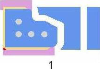
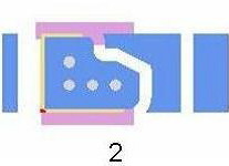
Update While Simulating Toggled "Off":
Notice that when Update While Simulating is toggled "Off", the pieces of excess stock that have been cut free from the workpiece remain displayed, as shown in the pictures below.
 |
|  |
| 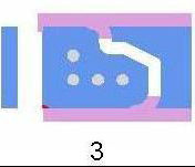
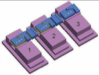
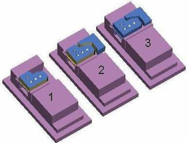
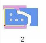
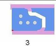
Update While Simulating Toggled "On":
Notice that when Update While Simulating is toggled "On", most of the pieces of excess stock that have been cut free from the workpiece have been automatically deleted, as shown in the picture below. The reason that they were not all automatically deleted is because of slight differences in the holding fixtures. In setups 2 and 3, the remaining excess stock pieces are at least partially in contact with the fixture so they were not automatically deleted.
![]() |
|  |
| 
Load All Stocks
Location:
Project tab >  (Load All Stocks)
Toolbar short cut: ![]()
After cutting, selecting the Load All Stocks command button causes Vericut to load new stock models for Stock components having models defined, but a cut stock model does not exist. This capability is used when simulating a series of parts being machined through multiple machining stages. This type of manufacturing is often referred to as "staged machining".
In general, the following actions take place in staged machining:
-
Simulate the first stage cutting operation. (Creates a "Cut Stock" workpiece that appears as
 in the Component Tree window)
 -
Move (e.g. cut and paste) the cut stock to a different Stock component defined to represent the next cutting stage.
- Select Load All Stocks to load a new uncut stock model in the first cutting stage.
- Continue cutting-typically cutting the first and second stages, but may cut all stages even though workpieces have not yet been placed in subsequent cutting stages.
- Repeat actions as required to cut a workpiece through all cutting stages required to complete the final part configuration.