CoroPlus Tool Import Interface window
Locations:
Tool Manager > Import ribbon > Partners group >  (CoroPlus Tool)
The CoroPlus Tool Import Interface window enables you to easily download Sandvik’s 3D tool models from the CoroPlus ToolLibrary and quickly transfer them to a Vericut tool library via a GTC package zip file. In the Tool Manager Import ribbon, click on the CoroPlus Tool command button from the Partners group to display the Import CoroPlus Tools window shown below. Cutting data can also be read in for certain Sandvik tooling during the import process for use in toolpath optimization within Vericut and Tool Manager to run additional checks on your simulation.
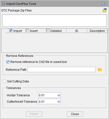
GTC Package Zip Files — Enter the \path\filename of the .zip file containing the list of the tool models that you want to import in the text field, or click on the  (Browse) and use the Select CoroPlus Files file selection window that displays to specify the \path\filename of the .zip file containing the list of the tool models. Multiple zip files can be selected at once to import multiple tools.
Tool Table — After specifying the CoroPlus tool file, the Tool Table will be populated with a list of the tool models contained in the CoroPlus tool file.
-
Import — Toggle on (checked by default) to ensure that the selected tool is imported when Import is clicked.
-
Insert — Toggle on (checked) to import a tool so the cutter is defined as an insert (cutter) component.
-
Detailed — Toggle on (checked) to import the detailed 3d model (if available) from the GTC.zip file. (📝 NOTE: some tools in the GTC.zip file may or may not contain detailed models)
-
ID — Populates using the Name field from CoroPlus ToolLibrary. This Name will be used as the Tool ID in Tool Manager.
-
Description — Populates with the Description field from CoroPlus ToolLibrary. This Description will be used as the Description in Tool Manager. If a Description is not added in CoroPlus ToolLibrary the Name (ID) will be used as the Description
Remove reference to CAD file in the saved tool — When toggled "off" (not checked), the imported tool models are stored in the same CAD format that they were imported in. When toggled "on" (checked), the imported tool components are saved as Vericut Polygon files.
📝 NOTE: The Model Tolerance value specified in Settings window: Properties tab (Project tab > Settings > Properties tab > Tolerance section) is used when creating the Vericut Polygon (.ply) files.
Reference Path – Option to control where the .ply files from imported tools are stored.
-
If there is no .tls file saved/present prior to when tools are first imported, the .ply files by default go to the working directory.
If a .tls file is saved/present prior to when tools are imported, the .ply files default to the location of the .tls file (may not be the current working directory). -
By default, the Reference Path field will not display a path until
(Browse) is opened and a path is selected. -
If "Remove reference to CAD file in saved tool" is UNCHECKED, "Reference path" option is greyed out and not available (will reference where .stp files currently reside).
Get Cutting Data — when toggled on (checked), the Get Cutting Data option enables you to add Stock Material Records to the tool assemblies being imported that contain cutting limits and optimization settings for use in the optimization of the NC Program. This option remains modal until changed by the user. See Getting Cutting Data for Use in Optimization for additional information.
Holder Tolerance — Enables you to specify the Holder Tolerance by entering the tolerance value in the Holder Tolerance text field.
Cutter/Insert Tolerance — Enables you to specify the Cutter/Insert Tolerance by entering the tolerance value in the Cutter/Tolerance text field.
📝 NOTE: When specifying Holder Tolerance and Cutter/Insert Tolerance values, the specified values will be applied to Holder Tolerance and Cutter/Insert Tolerance in the Tool Manager Preferences window, the Import CAD Tool window and the Import CoroPlus Tools window.
Import — Use to import the designated tool models from the CoroPlus Tool zip file to the currently active Vericut tool library and then close the CoroPlus Tool Import Interface window.
Close — Close the CoroPlus Tool Import Interface window without importing the specified tool models.
GTC Package .zip File Information
GTC (Generic Tool Catalog) is a format to complement the ISO 13399 standard that Sandvik’s CoroPlus platform utilizes for exchanging data between cutting tool vendors and applications. The term GTC node refers to each cutting-tool component that is described according to ISO 13399. The CoroPlus Interface to Vericut supports the following GTC node cutter types:
| GTC Node | Description | CGTech Tool Type | CGTech Cutter Type |
|---|---|---|---|
| BORISBI | Boring tool, back counterbore, indexable | Milling | Insert Cutter |
| DRLCONSS | Drill, Conical hole drill, solid, -symmetrical point | Holemaking | Rev. Profile |
| DRLCTRSA | Drill, Center drill, solid, Form A DIN/ISO | Holemaking | Rev. Profile |
| DRLCTRSB | Drill, Center drill, solid, Form B DIN/ISO | Holemaking | Rev. Profile |
| DRLCTRSNS | Drill, Center drill, solid, Non standard form | Holemaking | Rev. Profile |
| DRLCTRSR | Drill, Center drill, solid, Form R DIN/ISO | Holemaking | Rev. Profile |
| DRLFIA | Drill, Cylindrical hole drill, indexable, -asymmetrical point | Holemaking | Rev. Profile |
| DRLFIS | Drill, Cylindrical hole drill, indexable, -symmetrical point | Holemaking | Rev. Profile |
| DRLFSGP | Drill, Cylindrical hole drill, solid, -guide pad | Holemaking | Rev. Profile |
| DRLFSS | Drill, Cylindrical hole drill, solid, -symmetrical point | Holemaking | Rev. Profile |
| DRLSPTS | Drill, Spot drill, solid | Holemaking | Rev. Profile |
| MILBNRI | Ball nose milling cutter, Ball nose with radius side, indexable | Milling | Rev. Profile |
| MILBNRS | Ball nose milling cutter, Ball nose with radius side, solid | Milling | Rev. Profile |
| MILBNSI | Ball nose milling cutter, Ball nose with straight side, indexable | Milling | Rev. Profile |
| MILBNSS | Ball nose milling cutter, Ball nose with straight side, solid | Milling | Rev. Profile |
| MILCFBI | Chamfer milling cutter, Chamfer mill - front and back cutting, indexable | Milling | Rev. Profile |
| MILCFBS | Chamfer milling cutter, Chamfer mill - front and back cutting, solid | Milling | Rev. Profile |
| MILCFI | Chamfer milling cutter, Chamfer mill - front cutting, indexable | Milling | Rev. Profile |
| MILCFS | Chamfer milling cutter, Chamfer mill - front cutting, solid | Milling | Rev. Profile |
| MILFI | Milling cutter, Face milling cutter, indexable | Milling | Rev. Profile |
| MILFS | Milling cutter, Face milling cutter, solid | Milling | Rev. Profile |
| MILGS | Groove milling cutter, solid | Milling | Rev. Profile |
| MILPRAPS | Profiled milling cutter, Angle profile mill, solid | Milling | Rev. Profile |
| MILPRHCS | Profiled milling cutter, Quarter circle profile mill, solid | Milling | Rev. Profile |
| MILPRQCS | Profiled milling cutter, Quarter circle profile mill, solid | Milling | Rev. Profile |
| MILSFDHI | Milling cutter, Side and face mill, Double half side and face mill, indexable | Milling | Rev. Profile |
| MILSFFI | Milling cutter, Side and face mill, Full slot side and face mill, indexable | Milling | Rev. Profile |
| MILSFFS | Milling cutter, Side and face mill, Full slot side and face mill, solid | Milling | Rev. Profile |
| MILSFHI | Milling cutter, Side and face mill, Half side and face mill, indexable | Milling | Rev. Profile |
| MILSQI | Milling cutter, Shoulder face mill, indexable | Milling | Rev. Profile |
| MILSQS | Milling cutter, Shoulder face mill, solid | Milling | Rev. Profile |
| MILTHACS | Thread milling cutter, Thread mill - axial chamfering, solid | Milling | Rev. Profile |
| MILTHDCS | Thread milling cutter, Thread mill - drill and chamfer, solid | Milling | Rev. Profile |
| MILTHGS | Thread milling cutter, Thread mill, solid | Milling | Rev. Profile |
| MILTHMCS | Thread milling cutter, Thread mill - helical mill and chamfer, solid | Milling | Rev. Profile |
| MILTHOCS | Thread milling cutter, Thread mill - orbital chamfering, solid | Milling | Rev. Profile |
| MILTSI | T-slot milling cutter, indexable | Milling | Rev. Profile |
| MILTSS | T-slot milling cutter, solid | Milling | Rev. Profile |
| REASCYLS | Reamer, cylindrical hole, solid | Holemaking | Rev. Profile |
| TAPCCONF | Tap, Cutting tap for conical threads, chip flutes | Holemaking | Tap |
| TAPCCYLD | Tap, Cutting tap for cylindrical threads, drilling function | Holemaking | Tap |
| TAPCCYLF | Tap, Cutting tap for cylindrical threads, chip flutes | Holemaking | Tap |
| TAPCCYLG | Tap, Cutting tap for cylindrical threads, gun nose | Holemaking | Tap |
| TAPFCYL | Tap, Forming tap for cylindrical threads | Holemaking | Tap |
| TRNGEI | Turning tool, Tool holder, general turning, external turning tool, indexable | Turning | Insert Cutter |
| TRNGIBI | Turning tool, Internal turning tool, boring, indexable | Turning | Insert Cutter |
| TRNPAI | Turning tool, grooving, indexable | Turning | Insert Cutter |
| TRNPEI | Turning tool, Tool holder, general turning, external OD grooving, indexable | Turning | Insert Cutter |
| TRNGIBBI | Turning tool | Turning | Insert Cutter |
| TRNGIBS | Turning tool | Turning | Insert Cutter |
| TRNPII | Turning tool, grooving | Turning | Insert Cutter |
| TRNPIS | Turning tool, grooving | Turning | Insert Cutter |
Getting Technology Data for Use in Optimization
The CoroPlus Interface has the option to store what is commonly known in Vericut as “cutting limits and optimization settings” or “performance parameters” along with the cutting tool geometry information. In CoroPlus Interface these cutting limits and optimization settings are referred to as Cutting Data for each tool assembly. This Cutting Data can be used in Vericut and Tool Manager to run additional checks on your simulation as well as be utilized with Force.
If you intend to run these additional checks and perform optimization (Force) on your NC Program, you will need to have the cutting limits and optimization settings for a particular tool assembly being used on a specific CNC machine cutting a specific material. These performance parameters may also be specific to each application of how that tool assembly is being used (I.e. roughing, semi-finishing, finishing, etc.)
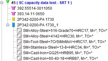
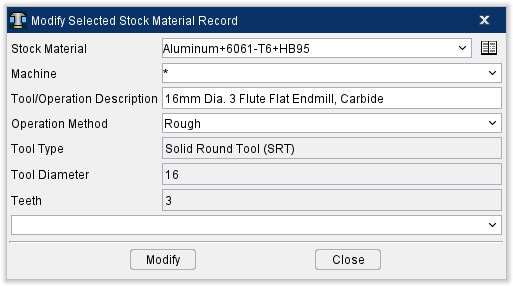
The cutting limits and optimization settings are stored in Vericut’s Tool Manager in Stock Material Records, attached to the cutter of each Tool ID. Each Tool ID could have just one Stock Material Record or multiple depending on how many different materials can be cut with that specific cutter.

The name of the Vericut Stock Material Record is comprised of the following 3 pieces of information that is entered into the Add Stock Material Record window:
• SM = (Stock Material) Name of the material that is being cut
• M = (Machine) CNC machine name
• TO = (Tool/Operation Description) Description of the application for this situation
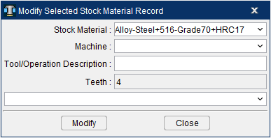
Currently the default Stock Material Record names will consist of only what is in the Stock Material field.
When the Stock Material Record is created through the CoroPlus Interface it is necessary to match the Sandvik Reference Material name to the appropriate Stock Material Record name in Vericut. Matching Stock Material Record name is necessary once you get into the optimization process in order to correctly match the Force Material File in Vericut.
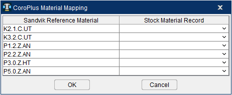
For the above described reasons, when Get Cutting Data is toggled ON (checked) in the Import CoroPlus Tools window and Import button is clicked, it will open the Machine and Material Mapping window.

Sandvik Reference Material — This will populate with all the Reference Material ID’s listed for the Sandvik cutter(s).
📝 NOTE: Single or multiple Sandvik tools can be imported at once via the CoroPlus Interface. A single tool assembly may contain a single or multiple Sandvik Reference Materials. If multiple tools are being imported the Sandvik Reference Material list will consist of all the Reference Material ID’s from all tools being imported).
Stock Material Record — Displays the Stock Material Record names that are available from the Force Material File Directory in Vericut and any Stock Materials listed in Tool Manager. This optional selection is intended to align existing Stock Material Records within Vericut to a Workpiece Material name for use with Force and Optimization. The default will display empty field.
OK — Will continue to read in each tool assembly and create Stock Material Records for all records with a Stock Material Record mapped. If a Stock Material Record is not mapped for that specific Sandvik Reference Material, the tool will be generated without that specific Stock Material Record.
Cancel — Closes the CoroPlus Material Mapping window without creating any tools in Tool Manager and returns to the Import CoroPlus Tools window.
📝 NOTE: The mapping of an single or multiple Sandvik Reference Materials will depend on your workflow. If you are only concerned with getting a specific Stock Material Record(s) for a specific material you are simulating then only map the desired Stock Material Record(s) as needed. If you are doing a master tool library where you want all the Stock Material Records for a given tool, then all map all the Stock Material Records accordingly in the Mapping window.
Getting Cutting Data for Use in Optimization
The CoroPlus Interface has the option to store what is commonly known in Vericut as “cutting limits and optimization settings” or “performance parameters” along with the cutting tool geometry information. In CoroPlus Interface these cutting limits and optimization settings are referred to as Cutting Data for each tool assembly. This Cutting Data can be used in Vericut and Tool Manager to run additional checks on your simulation as well as be utilized with Force.
If you intend to run these additional checks and perform optimization (Force) on your NC Program, you will need to have the cutting limits and optimization settings for a particular tool assembly being used on a specific CNC machine cutting a specific material. These performance parameters may also be specific to each application of how that tool assembly is being used (I.e. roughing, semi-finishing, finishing, etc.)
The cutting limits and optimization settings are stored in Vericut’s Tool Manager in Stock Material Records, attached to the cutter of each Tool ID. Each Tool ID could have just one Stock Material Record or multiple depending on how many different materials can be cut with that specific cutter.
The name of the Vericut Stock Material Record is comprised of the following 3 pieces of information that is entered into the Add Stock Material Record window:
• SM = (Stock Material) Name of the material that is being cut
• M = (Machine) CNC machine name
• TO = (Tool/Operation Description) Description of the application for this situation
Currently the default Stock Material Record names will consist of only what is in the Stock Material field.
When the Stock Material Record is created through the CoroPlus Interface it is necessary to match the Sandvik Reference Material name to the appropriate Stock Material Record name in Vericut. Matching Stock Material Record name is necessary once you get into the optimization process in order to correctly match the Force Material File in Vericut.
For the above described reasons, when Get Cutting Data is toggled ON in the Import CoroPlus Tools window and Import button is clicked, it will open the Machine and Material Mapping window.
Sandvik Reference Material — This will populate with all the Reference Material ID’s listed for the Sandvik cutter(s).
📝 NOTE: Single or multiple Sandvik tools can be imported at once via the CoroPlus Interface. A single tool assembly may contain a single or multiple Sandvik Reference Materials. If multiple tools are being imported the Sandvik Reference Material list will consist of all the Reference Material ID’s from all tools being imported.
Stock Material Record — Displays the Stock Material Record names that are available from the Force Material File Directory in Vericut and any Stock Materials listed in Tool Manager. This optional selection is intended to align existing Stock Material Records within Vericut to a Workpiece Material name for use with Force and Optimization. The default will display empty field.
OK — Will continue to read in each tool assembly and create Stock Material Records for all records with a Stock Material Record mapped. If a Stock Material Record is not mapped for that specific Sandvik Reference Material, the tool will be generated without that specific Stock Material Record.
Cancel — Closes the CoroPlus Material Mapping window without creating any tools in Tool Manager and returns to the Import CoroPlus Tools window.
📝 NOTE: The mapping of an single or multiple Sandvik Reference Materials will depend on your workflow. If you are only concerned with getting a specific Stock Material Record(s) for a specific material you are simulating then only map the desired Stock Material Record(s) as needed. If you are doing a master tool library where you want all the Stock Material Records for a given tool, then all map all the Stock Material Records accordingly in the Mapping window.