Settings group
Location:
X-Caliper tab > Settings group
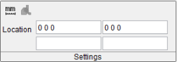
The Settings section is a dynamic section that updates depending on what features and options are selected from other X-Caliper sections. The default section is shown below:

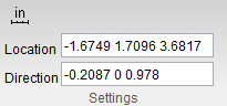
The most common features that appear in this group are the Location and Direction fields. When these features are present in the Settings group, they are editable text fields. Location tells you the CSYS of where you clicked on the stock you are measuring and Direction indicates which axis the feature is measuring along. For instance, when using Model Thickness a Direction of 0 -1 0 would indicate that thickness is being measured downward along the Y axis.
Selecting the Diameter/Radius, *Center of Gravity, Volume, Scallop, Save Dimension, Delete Dimension, or View Capture command buttons does not alter the Settings group.
Options:
-
 (Inch) — Specifies that measurements be displayed in inches. Click on the icon to change it to:
 -
 (Millimeter) — Specifies that measurements be displayed in millimeters. Click on the icon to change it back to .
 -
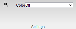
 (Show Collision) — This option is grayed out until a collision is detected when a simulation is being run.
The following shows how the Settings group is displayed for specific command buttons.
Feature/History command button selected
Model Thickness, Air Distance, or Distance command buttons selected
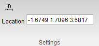
Closest Point command button selected
Highlight Plane/Cylinder command button selected
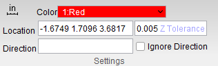
You can toggle Ignore Direction on (checked) to void the Direction field. Otherwise the Direction field will still be editable.
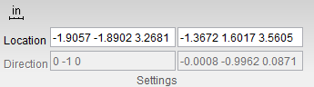
Plane to Point, Axis to Axis, From, To, Axis Intersection command buttons selected
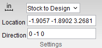
Stock/Design Distance command button selected
Hole Top, Hole Bottom, Feature, or C-Sink command buttons selected