Machine Offsets, Machine Offsets panel
Location:
Info tab >  (Machine Offsets)
Toolbar short cut: ![]()
The features on the Machine Offsets panel enable you to view the values that are set for each machine offset and determine whether a particular machine offset is currently active.
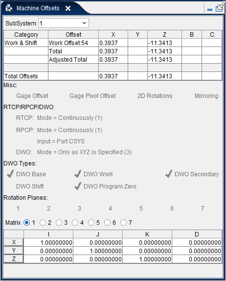
The Machine Offsets panel enables you to view the values that are set for each machine offset and determine whether a particular machine offset is currently active. If you "Single Step" through the NC program, the displayed values update at the end of each motion. When you are using "Play to End", the displayed values are updated each time you "Stop" processing or when processing stops at the end of the NC program. The Machine Offsets panel is intended for debugging purposes only. The window displays current values set for each offset and whether the offset is currently active. You cannot modify the values directly in the Machine Offsets panel. The values must be edited in the table or macro in which they were originally set.
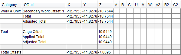
The offsets are grouped into 4 categories: Work & Shift, Tool, Other, and Total Offsets, as shown in the Category column in the window above. Each Category can consist of a number of different machine offsets and are displayed in the Offsets column. The remaining columns indicate the offset values that are set/applied for each machine axis. Each particular offset will only displayed if it contains non-zero values. If all offsets within a Category are zero, then the Category will not be displayed. The exception to this rule is the Total Offsets Category which will always be displayed.
This panel also contains a series of flags associated with offsets and transformations.
The Machine Offsets panel is one of the dockable panels enabling you to dock it inside the Vericut main window if you choose. See Personalizing the Vericut Main Window section of Vericut Help for additional information.
📝 NOTE: When the Machine Offsets panel is docked, make sure that you click in the panel so that it becomes the "active" panel before using F1 to get help specific to the panel. Otherwise F1 will go to the Vericut Help Library.
 (Close) — Located at the end of the tab, this icon enables you to close the Machine Offsets panel.
 (Close) — Closes the Machine Offsets panel. This icon is only displayed when the Machine Offsets panel is not docked.
SubSystem — All values displayed in the Machine Offsets panel are specific to a particular subsystem. If the machine configuration has more than one subsystem, use this feature to select the desired subsystem.
Offset Categories
Work & Shift:
These offsets are in a separate category because the DynamicWorkOffsets feature applies to these offsets.
Base Work Offset — Base Work Offset is affected by the following macros:
-
SetBaseWorkOffset
-
CancelWorkOffsets
-
EnableWorkShiftOffsets
-
DisableWorkShiftOffsets
-
CancelAllWorkOffsets
-
BaseWorkOffsetValues
For information about these, and all, Vericut macros, see the Vericut Macros section, in the Vericut Help Library.
📝 NOTE: This offset is automatically applied during reset.
Work Offset — Work Offset is affected by the following macros:
-
WorkCoord
-
AdditionalWorkCoord
-
SetBaseWorkOffset
-
CancelWorkOffsets
-
EnableWorkShiftOffsets
-
DisableWorkShiftOffsets
-
CancelWorkOffsets
-
CancelAllWorkOffset
For information about these, and all, Vericut macros, see the Vericut Macros section, in the Vericut Help Library.
📝 NOTE: This can also be set from the Machine/Control tab > Control Settings: Offsets tab.
Secondary Work Offset — Secondary Work Offset is affected by the following macros:
-
SecondaryWorkCoord
-
SecondaryRefWorkCoord
For information about these, and all, Vericut macros, see the Vericut Macros section, in the Vericut Help Library.
Shift 1 — Shift 1 is affected by the following macros:
-
ChangeWorkCoord
-
AbsoluteShift, IncrementalShift
-
EnableWorkShiftOffsets
-
DisableWorkShiftOffsets
-
CancelShiftOffsets
-
CancelAllWorkOffsets
-
SiemensShiftOffsetA
-
SiemensL137COffset
-
SiemensL137CoffsetCancel
For information about these, and all, Vericut macros, see the Vericut Macros section, in the Vericut Help Library.
Shift 2 — Shift 2 is affected by the following macros:
-
AbsoluteShiftNum
-
OkumaCopyStart
-
OkumaCopyEnd
-
OkumaShiftRotate
-
OkumaCancelShiftRotate
-
SiemensShiftOffsetB
For information about these, and all, Vericut macros, see the Vericut Macros section, in the Vericut Help Library.
Shift 3 — Shift 3 is affected by the following macros:
-
NumLengthCompX
-
NumLengthCompY
-
NumLengthCompZ
For information about these, and all, Vericut macros, see the Vericut Macros section, in the Vericut Help Library.
Total — The combined total of all of the above offsets.
Adjusted Total — The resulting total after the corresponding rotations have been applied.
Tool: — In many cases, an offset will be applied to the machine based on the tool offset and the orientation of the tool. The tool offset can actually be composed of several pieces; some of which are mutually exclusive.
Gage Offset — This value is typically calculated from the tls file. It is the "Gage Offset" minus the "Ctrl Pt". You can override the value from the tls file with an entry in the Gage Offset Table. This value is typically set with a tool change. Its value can also be updated with a call to the ToolOffsetUpdate macro
Tool Length Offset — This value is typically only used if the Programming Method is set to Tool Length Compensation. This value can, however, be used in all 3 Programming Methods. The value will be set based on the corresponding entry in the Tool Length Compensation table. If no entry exists, and the Programming Method is set to Tool Length Compensation, this value will be set to the Z value of the Input Program Zero + the Z value of the Gage Offset. Tool Length Offset is affected by the following ToolLengthComp... macros:
-
ToolLengthCompUpdate
-
ToolLengthCompPos
-
ToolLengthCompNeg
-
ToolLengthCompOff
-
ToolLengthCompValue ToolLengthCompToolnum
-
SiemensPlaneSelectionArg
For information about these, and all, Vericut macros, see the Vericut Macros section, in the Vericut Help Library.
Tool Nose Comp — Tool Nose Comp is affected by the following ToolNoseComp... macros:
-
ToolNoseCompApply
-
ToolNoseCompCancel
-
ToolNoseCompToolNum
-
ToolNoseCompValue
For information about these, and all, Vericut macros, see the Vericut Macros section, in the Vericut Help Library.
Turret Offset — The turret offset is defined to be the XYZ distance from the active tool to the center of its corresponding Turret. This offset can be turned on and off. When turned on, this offset will be set with calls to either TurretActivateTool or TurretToolChange macros. It can also be reset to zero if the current gage offset is set to zero and the apply turret offset flag is set accordingly. This flag is set with the ApplyTurretOffset macro.
For information about these, and all, Vericut macros, see the Vericut Macros section, in the Vericut Help Library.
GagePivotOffset — This offset is used as an alternative approach to RTCP (Dynamic Tool Offsets). RTCP has been based on the concept of the spindle face being the driven point when there is no tool in the spindle. When a tool is loaded, and then rotated, both the gage offset and the pivot offset needs to be adjusted. When driving the center of the pivot, and then adjusting for the gage and pivot offset, the calculation is different. This offset is used for this latter approach. Its functionality is currently limited. The capability is turned on with the ApplyGagePivotOffset macro, and its value is updated whenever the tool offsets are updated. This capability is mutually exclusive with RTCP.
For information about these, and all, Vericut macros, see the Vericut Macros section, in the Vericut Help Library.
Current RTCP Pivot Offset — The pivot offset can set be set in the RTCP Pivot Offset Table. If the corresponding entry does not exist, it will be auto-calculated based on the active tool component and the position of the corresponding parent rotary components. The application of this offset can be turned on, or off, using the ApplyPivotOffset macro. When applied, it will be adjusted based on the orientation of the tool. It assumes that in its initial state, no offsets are to be applied. The initial state is set at start of processing, and can be updated with a call to the SetPivotOffset macro.
For information about these, and all, Vericut macros, see the Vericut Macros section, in the Vericut Help Library.
Applied Total — This is the sum of the Tool offsets, which are currently being applied.
📝 NOTE: Not all of the offsets listed will be applied. For example: Gage Offset values might be specified, but may not be applied because the Programming Method is set to Gage Length.
Adjusted Total — This value takes the applied total, possibly adjusts it based on the orientation of the tool, and then applies it to the corresponding axis. See the following macros:
-
XToolOffsetCompName
-
YToolOffsetCompName
-
ZToolOffsetCompName
For information about these, and all, Vericut macros, see the Vericut Macros section, in the Vericut Help Library.
Other:
Dynamic 3D Tool Offset — See Tool3dOffset in the Vericut Macros section in the Vericut Help Library.
3D Tool Length Comp — The Tool Length Offset as describe above, is an offset, which applies only to Z. There is special handling of this value within the software, and has therefore not been grouped with the Tool offsets. This offset can be applied to any axis. See FanucToolLengthComp and ToolLengthCompOff in the Vericut Macros section, in the Vericut Help Library.
Input Program Zero — This offset is typically set in the Input Program Zero (Special Z) table. The values are automatically activated during initialization, and can be updated with calls to UpdateIPZ and AutoUpdateIPZ macros. When the Programming Method is set to Tool Length Compensation, the Z value of the IPZ will not be applied. In this programming method, the Z value might later be used in the calculation of the Tool Length Offset.
Input Machine Zero — This offset is set in the Machine Zero table and is automatically activated during initialization. Typically, this offset is not used.
Miscellaneous — Other offsets that might be applied – intentionally not defined.
Total — Sum of the above offsets.
Total Offsets:
Sum of all offsets being applied.
📝 NOTE: This does not include rotation planes.
Active Translations/Rotations:
The following features become highlighted and checked when the particular translation/rotation is active. Gage Offset and Gage Pivot Offset are shown in their "active" states in the picture below.
![]()
Gage Offset — The Gage Offset is the offset from the driven point of the tool (typically the tool tip) to the Gage Point of the tool (the point where the tool connects to the Tool Component).
Default: The default is based on the Programming Method. The default is On if the Programming Method is Tool Tip, and is Off if the Programming Method is anything else.
The Gage Offset feature is turned On (checked), and Off (not checked), with calls to the following macros:
-
ApplyGageOffset (Status = Obsolete)
-
TurnOnOffGageOffset
For information about these, and all, Vericut macros, see the Vericut Macros section, in the Vericut Help Library.
Gage Pivot Offset — The Gage Pivot Offset is the offset from the tool component to the Pivot point of the machine (typically the parent rotary component).
Default: Off.
The Gage Pivot Offset feature is turned On (checked), and Off (not checked), with calls to the following macros:
-
ApplyGagePivotOffset (Status = Obsolete)
-
ApplyGagePivotOffsetCurrent (Status = Obsolete)
-
TurnOnOffGagePivotOffset
For information about these, and all, Vericut macros, see the Vericut Macros section, in the Vericut Help Library.
2D Rotations — 2D Rotations are defined within the active plane (XY, YZ or ZX).
Default: Off
The 2D Rotations feature is turned On (checked), and Off (not checked), with calls to the following macros:
-
RotateXYZ
-
RotateCancel
-
RotateOrigin
-
RotateMacro
For information about these, and all, Vericut macros, see the Vericut Macros section, in the Vericut Help Library.
Mirroring — The Mirroring feature is active if the data is to be mirrored about any axis.
Default: Off
The Mirroring feature is turned On (checked), and Off (not checked), with calls to the following macros:
-
MirrorX
-
MirrorY
-
MirrorZ
-
MirrorA
-
MirrorB
-
MirrorC
-
MirrorA2
-
MirrorB2
-
MirrorC2
-
MirrorXValue
-
MirrorYValue
-
MirrorZValue
-
MirrorAValue
-
MirrorBValue
-
MirrorCValue
-
MirrorA2Value
-
MirrorB2Value
-
MirrorC2Value
-
MirrorCancel
-
MirrorXCancel
-
MirrorYCancel
-
MirrorZCancel
-
MirrorACancel
-
MirrorBCancel
-
MirrorCCancel
-
MirrorA2Cancel
-
MirrorB2Cancel
-
MirrorC2Cancel
For information about these, and all, Vericut macros, see the Vericut Macros section, in the Vericut Help Library.
3D Rotation Planes — Vericut supports multiple matrix transformations of the input data, including: 3D Rotation Planes, Working Planes, Virtual Y (used with slant bed lathes), and RPCP. This feature is active if 3D Rotation Planes are currently being applied.
Default: Off
The 3D Rotation Planes feature is turned On (checked), and Off (not checked), with calls
to the following macros:
-
FanucRotationPlaneLocal2
-
RotationPlane
-
RotationPlane2
-
RotationPlaneEnable2
-
RotationPlaneLocal
-
RotationPlaneCancel
-
RotationPlaneCancel2
-
RotationPlaneCancelReset
-
FidiaRotate
-
FidiaRotate2
-
FidiaRotateCancel
-
FidiaRotateCancel2
-
NumPlane
-
Siemens_P_PFRAME
-
SiemensSystemFramesCancel
-
SiemensSystemFramesRestore
-
SiemensTOFRAME
-
SiemensTOROTOF
-
WorkingPlane2Abc
For information about these, and all, Vericut macros, see the Vericut Macros section, in the Vericut Help Library.
Working Planes — Vericut supports multiple matrix transformations of the input data, including: 3D Rotation Planes, Working Planes, Virtual Y (used with slant bed lathes), and RPCP. This feature is active if Working Planes are currently being applied.
Default: Off
The Working Planes feature is turned On (checked), and Off (not checked), with calls to the following macros:
-
WorkingPlane
-
WorkingPlaneCancel
For information about these, and all, Vericut macros, see the Vericut Macros section, in the Vericut Help Library.
RTCP/RPCP/DWO:
This section displays the state (active/inactive) of the modes associated with Rotary Tool Control Point (RTCP), Rotary Part Control Point (RPCP), and DynamicWorkOffsets (DWO). For each of these features, three different modes are available.
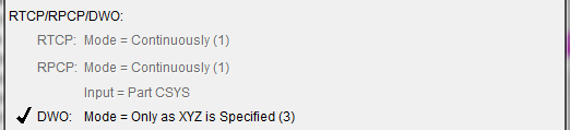
In the picture above, RTCP Mode and RPCP Mode are all grayed out indicating that RTCP and RPCP are not turned on. Notice that even though the mode is set to Continuously for both of these features, they will not be acted on because the main features have not been turned on.
I the picture above, DWO Mode, the main feature, is turned On and mode Only as XYZ is Specified is active.
In general:
-
If RTCP is turned off, RTCP Mode is grayed out.
-
If RPCP is turned off, RPCP Mode is grayed out.
- If DWO is turned off, RTCP Mode and DWO Mode are grayed out.
Each of the main features and their associated modes are described below.
RTCP Mode — Rotary Tool Control Point (RTCP) determines whether the Tool related offsets should automatically be updated when the tool rotates.
Default: The default is set using the Rotary Tool Control Point feature on the Configuration tab > Control Settings: Rotary tab.
The RTCP Mode feature is turned On and Off with calls to the following macros:
-
RtcpOn
-
RtcpOff
-
RotaryControlPointOnOff
For information about these, and all Vericut macros, see the Vericut Macros section, in the Vericut Help Library.
The following RTCP modes are available for use.
Default: The default is set using the RTCP Mode feature on the Configuration tab > Control Settings: Rotary tab.
(1) Continuously — The machine’s axes will be continually updated as the tool rotates in order to keep the tool tip on path. This means that if only an A rotation is programmed (assume A is a rotary on the Tool Side), then all axes will move in order to keep the tool tip motionless as the tool rotates.
(2) At End Point — The final end point is calculated, and the machine is sent directly to this location. The end result is: if only an A rotation is programmed (assume A is a rotary on the Tool Side), then the tool tip will move as the tool rotates, but it will end up in its original location.
(3) Only as XYZ is Specified — If XYZ is specified on the block with the rotary move, then this mode is the same as “At End Point”. If XYZ is not specified on the block with the rotary move, then only the rotary will move. As each axis is specified, the corresponding offset will then be applied.
The RTCP mode is specified with calls to the RtcpMode macro.
For information about RtcpMode and all Vericut macros, see the Vericut Macros section, in the Vericut Help Library.
RPCP Mode — Rotary Part Control Point (RPCP) determines if the coordinate system should rotate automatically as the part rotates.
Default: Off
The RPCP Mode feature is turned On and Off with calls to the following macros:
-
RpcpOn
-
RpcpOff
-
RotaryControlPointOnOff
For information about these, and all Vericut macros, see the Vericut Macros section, in the Vericut Help Library.
The following RPCP modes are available for use.
(1) Continuously — The machine’s axes will be continually updated as the part rotates in order to keep the tool tip on path. This means that if only an A rotation is programmed (assume A is a rotary on the Part Side), then all axes will move in order to keep the tool tip motionless (relative to the part) as the part rotates.
(2) At End Point — The final end point is calculated, and the machine is sent directly to this location. The end result is: if only an A rotation is programmed (assume A is a rotary on the Part Side), then the tool tip will move (relative to the part) as the part rotates, but it will end up in its original location (relative to the part)
(3) Only as XYZ is Specified — If XYZ is specified on the block with the rotary move, then this mode is the same as “At End Point”. If XYZ is not specified on the block with the rotary move, then only the rotary will move. As each axis is specified, the corresponding axis will be updated.
The RPCP mode is specified with calls to the RpcpMode macro.
For information about RpcpMode and all Vericut macros, see the Vericut Macros section, in the Vericut Help Library.
Input — Input determines if the input coordinates are assumed to be in part coordinates or local machine coordinates.
Input is specified with calls to the RpcpInput macro.
For information about RpcpInput and all Vericut macros, see the Vericut Macros section, in the Vericut Help Library.
The following values are available for use.
(0) Part CSYS — Defines the input coordinates as the part coordinates.
(1) Machine CSYS — Defines the input coordinates as local machine coordinates. In this mode, we will determine where we are currently relative to the part, and where we are going relative to the part, and cut in a straight line in part coordinate system, continually adjusting the machine XYZ positions to account for any rotations.
DWO Mode — Dynamic Work Offset (DWO) determines if the part side offsets should rotate automatically as the part rotates.
Default: Off
The DWO Mode feature is turned On and Off with calls to the DynamicWorkOffsets macro.
For information about DynamicWorkOffsets and all Vericut macros, see the Vericut Macros section, in the Vericut Help Library.
The following DWO modes are available for use.
(1) Continuously — The corresponding Dynamic Work Offsets will be continually updated as the part rotates in order to keep the tool tip on path.
(2) At End Point — The final end point is calculated, and the machine is sent directly to this location.
(3) Only as XYZ is Specified — If XYZ is specified on the block with the rotary move, then this mode is the same as “At End Point”. If XYZ is not specified on the block with the rotary move, then only the rotary will move. As each axis is specified, the corresponding offset will be applied.
The DWO mode is specified with calls to the DynamicWorkOffsetsMode macro.
For information about DynamicWorkOffsetsMode, and all Vericut macros, see the Vericut Macros section, in the Vericut Help Library.
DWO Types:
When Dynamic Work Offsets is turned on, part side offsets are updated as the part rotates. The specific types of offsets that will be updated are configurable. The following features correspond to each of the offsets types that can be configured to work with DWO.
DWO Base — DWO Base feature indicates whether or not the Base Work Offset should be updated as the part rotates (based on the Dynamic Work Offset (DWO) settings described above).
Default: On
The DWO Base feature is turned On (checked), and Off (not checked), with calls to the DynamicWorkOffsetsTypes macro.
For information about DynamicWorkOffsetsTypes, and all, Vericut macros, see the Vericut Macros section, in the Vericut Help Library.
DWO Work — DWO Work feature indicates whether or not the Work Offset should be updated as the part rotates (based on the Dynamic Work Offset (DWO) settings described above).
Default: On
The DWO Base feature is turned On (checked), and Off (not checked), with calls to the DynamicWorkOffsetsTypes macro.
For information about DynamicWorkOffsetsTypes, and all, Vericut macros, see the Vericut Macros section, in the Vericut Help Library.
DWO Secondary — DWO Secondary feature indicates whether or not the Secondary Work Offset should be updated as the part rotates (based on the Dynamic Work Offset (DWO) settings described above).
Default: On
The DWO Base feature is turned On (checked), and Off (not checked), with calls to the DynamicWorkOffsetsTypes macro.
For information about DynamicWorkOffsetsTypes, and all, Vericut macros, see the Vericut Macros section, in the Vericut Help Library.
DWO Shift — DWO Shift feature indicates whether or not the Shift Offsets should be updated as the part rotates (based on the Dynamic Work Offset (DWO) settings described above).
Default: On
The DWO Base feature is turned On (checked), and Off (not checked), with calls to the DynamicWorkOffsetsTypes macro.
For information about DynamicWorkOffsetsTypes, and all, Vericut macros, see the Vericut Macros section, in the Vericut Help Library.
DWO Program Zero — DWO Program Zero feature indicates whether or not the Program Zero Offset should be updated as the part rotates (based on the Dynamic Work Offset (DWO) settings described above).
Default: On
The DWO Base feature is turned On (checked), and Off (not checked), with calls to the DynamicWorkOffsetsTypes macro.
For information about DynamicWorkOffsetsTypes, and all, Vericut macros, see the Vericut Macros section, in the Vericut Help Library.
Rotation Plane Matrix/Working Plane Matrix:
Rotation Plane Matrix — The Rotation Plane Matrix represents the cumulative effect of all translations and rotations currently applied to the rotation plane. Its twelve parameters reveal the geometric attributes of the local (transformed) coordinate system (CSYS) relative to the machine origin. When active, the rotation plane matrix parameters are displayed in the matrix table format shown below.
This representation only includes translations and rotations resulting from using the RotationPlane... macros or the WorkingPlane2Abc macro.
The matrix values do not include the effect of using the Rpcp... macros or the VirtualXAxis / VirtualYAxis macros.
For information about these, and all, Vericut macros, see the Vericut Macros section, in the Vericut Help Library.
Working Plane Matrix — The Working Plane Matrix represents the cumulative effect of all translations and rotations currently applied to the working plane. Its twelve parameters reveal the geometric attributes of the local (transformed) coordinate system (CSYS) relative to the machine origin. When active, the working plane matrix parameters are displayed in the matrix table format shown below.
This representation only includes translations and rotations resulting from using the WorkingPlane macro.
The matrix values do not include the effect of using the Rpcp... macros or the VirtualXAxis / VirtualYAxis macros.
For information about these, and all, Vericut macros, see the Vericut Macros section, in the Vericut Help Library.
The format of the matrix table is as follows:
| I | J | K | D | |
|---|---|---|---|---|
| X | I1 | J1 | K1 | D1 |
| Y | I2 | J2 | K2 | D2 |
| Z | I3 | J3 | K3 | D3 |
Each row represents an axis of the local CSYS. The first three columns represent the vector associated with each axis: I1, J1, K1 as the positive X-axis vector; I2, J2, K2 as the positive Y-axis vector; and I3, J3, K3 as the positive Z-axis vector. The fourth column values D1, D2, D3 represent the coordinates of the origin point of the local CSYS.
📝 NOTE: If you prefer to see the Matrix Table displayed with the I, J, K along the vertical axis and the X, Y, Z along the horizontal axis, set the environment variable, CGTECH_MATRIX_FORMAT=VERTICAL.