Preferences (Preferences window)
Location:
Configuration tab >  (Preferences)
The Preferences command button opens the Preferences window enabling you to specify the Vericut project file (.VcProject) that you want displayed when you start the next Vericut session, the number of "recent files" that you want Vericut to remember, and the PDF reader/web browser that you want Vericut to use for online Help.
Start-up tab — Use the features on this tab to specify the Vericut project file (.VcProject) that you want displayed when you start the next Vericut session, the number of "recent files" that you want Vericut to remember.
PDF/HTM/Editor tab — Use the features in this tab to specify the location of the Adobe Reader and/or the location of the Internet Browser that you want Vericut to use to display online Help and/or the location of the NC program editor that you want to use.
Display tab — Use the features in this tab to specify display characteristics (Look & Feel, Font Size, Icon Size, etc.) that you want to use.
Appearance tab — Use the features of this tab to control the visuals of Fixture, Stock, Design, and Machine Component features.
Notifications — Use the features of this tab to specify which email will receive notifications about your project.
Application — Use the features of this tab to select various basic settings about your software.
Status Info tab — Use the features of this tab to control how information on the Status panel displays.
Graphs tab — Use the features of this tab to set certain Graphs features. This tab is only available in Vericut.
View Cube tab — Use the features in this tab to turn the View Cube On/Off/, specify View Cube window size and View Cube color settings.
Save Current Preferences — This feature enables you to save the current preferences file settings to an external file. Selecting Save Current Preferences displays the Save File file selection box enabling you to specify the /path/filename for the file to be saved.
OK — Saves the window settings and closes the Preferences window.
Apply — Apply the settings on the current tab.
Cancel — Closes the Preferences window without saving the window settings.
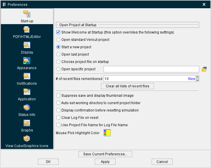
Start-up tab
The features on the Start-up tab enable you to specify the Vericut project file (.VcProject) that you want displayed when you start the next Vericut session, the number of "recent files" that you want Vericut to remember.
Show Welcome at Startup (this option overrides the following settings) — When toggled "on", this will display the Welcome Screen when Vericut is opened. Having this feature active means the next four features will not be active at Startup.
Open standard Vericut project — When toggled "on", the standard Vericut project is displayed upon startup. The standard Vericut project is either vericut.VcProject, or vericutm.VcProject, in the "library'" folder of your Vericut installation depending on the way environment variable, CGTECH_DEFAULT_UNITS, is set.
Start a new project — When toggled "on", the Vericut session opens and displays the New Vericut Project window enabling you to specify information related to the new project file to be created. This is the default preferences setting for the software. See New Project section of Vericut Help for information on the New Vericut Project window.
Open last project — When toggled "on", the new Vericut session opens with the same project file that was open when you closed the previous Vericut session.
Choose project file on startup — When toggled "on", Vericut displays the Open Project window at startup enabling you to select a project file.
Open a specific project — When toggled "on", designates your selected project file as the file the software will always open with.
# of recent files remembered — Use this feature to specify the number of "Recent Files" that you want Vericut to remember and display.
Clear all lists of recent files — Use this feature to clear all "Recent Files" lists. This includes the "Recent Files" lists in the File menu in the main Vericut window, Report Template window, and in the Inspection Sequence window.
Suppress save and display thumbnail image — When toggled “on” (checked), the saving of a thumbnail image when the project file is saved, and the display of the thumbnail image in the Open Project file selection box, are both suppressed.
Auto-set working directory to current project folder — When toggled “on” (checked), Vericut automatically sets the Working Directory to the folder that the “current” project file was located in.
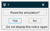
Display confirmation before resetting simulation — When toggled “on” (checked), generates a confirmation window when the simulation is reset. Choose Yes to reset and No to close the window. You can also set Do not display this notice again to On (checked) to reset the simulation without having to interact with this window again.
Clear Log File on reset — When toggled “on” (checked), the Log File will be cleared whenever you do a Reset Model.
Use Project File Name for Log File Name — Once this feature is toggled on (checked), the user will no longer see Vericut.log in the working directory. Instead there will be a project_name.log instead. The setting of this feature is saved in the preferences file.
Mouse Pick Highlight Color — Use the  (Color Palette) icon to specify a color for the “Mouse Pick” indicator
  . The right side of the (Color Palette) icon shows the current color for the “Mouse Pick” indicator. To change the color of the “Mouse Pick” indicator, click on the (Color Palette) icon to display the color palette window shown below.
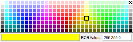
Click on a color in the color palette window, to specify the color for the “Mouse Pick” indicator. The color palette will close and the right side of the  (Color Palette) icon in the Preferences window: Start –up tab will update to reflect the selected color.
To close the color palette window without changing the color, click on the  in the upper right corner of the color palette.
Perform refine display in the background — When this feature is toggled off (not checked) Vericut waits for the refine display to finish before another user action is processed. Thus if you simulate something for a bit, with a small-ish cut tolerance (.003 on the standard Vericut part), and then zoom in close enough to get the good refine display image, such that refine display takes a noticeable amount of time (let’s say a few seconds), then you’ll notice that once you stop rotating the view you’ll need to wait until the view updates before the next rotate action is processed. This can create a kind of jerky motion that makes it hard to get the view orientation desired.
When this feature is toggled “on” (checked), the view updates in two stages; first a quick update happens, then a symbol appears in the lower right corner of the desktop as shown in the picture below;
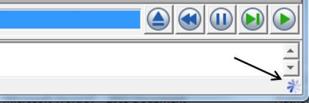
While this symbol is visible Vericut is refining the display using multiple processor threads. You can continue to do view manipulations of the quick and dirty image and the refine display will reset and begin again. If you settle on a view orientation long enough the refine will finish and you will see a nice crisp image.
PDF/HTML/Editor tab
The features on the PDF/HTML tab enable you to specify the Adobe Reader and/or Internet Browser that you want Vericut to use to display online Help.
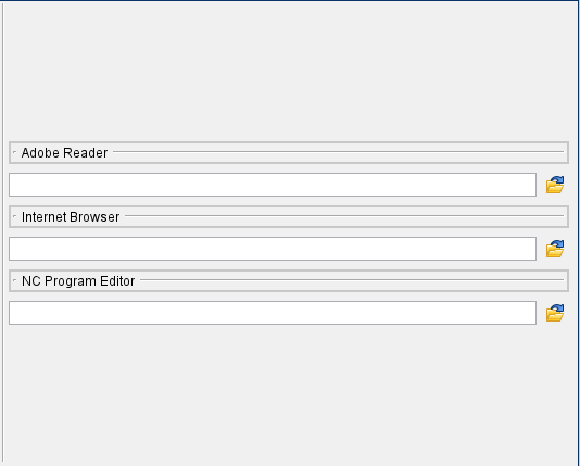
Adobe Reader — Enter the path/filename in the Adobe Reader text field, or click on the  (Browse) icon and use the Open file selection window that displays, to specify the path/file name of the Adobe Reader that Vericut is to use to display online Help.
📝 NOTE: This feature is only available on Windows computers.
Internet Browser — Enter the /path/filename in the Internet Browser text field, or click on the (Browse) icon and use the Open file selection window that displays, to specify the /path/filename of the internet browser that Vericut is to use to display online Help.
NC Program Editor — Enter the /path/filename of the NC program editor that you want to use in the NC Program Editor text field , or click on the (Browse) icon and use the Open file selection window that displays, to specify the /path/filename of the NC program editor that you want to use. This feature replaces the environment variable CGTECH_TPEDITOR.
All three of the above settings are stored in the Preferences File. For more information on the Preferences File, see Vericut File Descriptions section of Vericut Help.
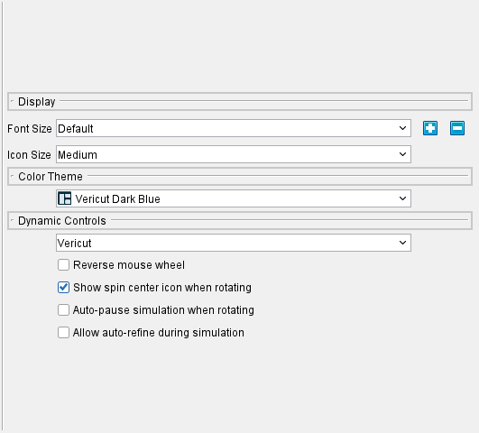
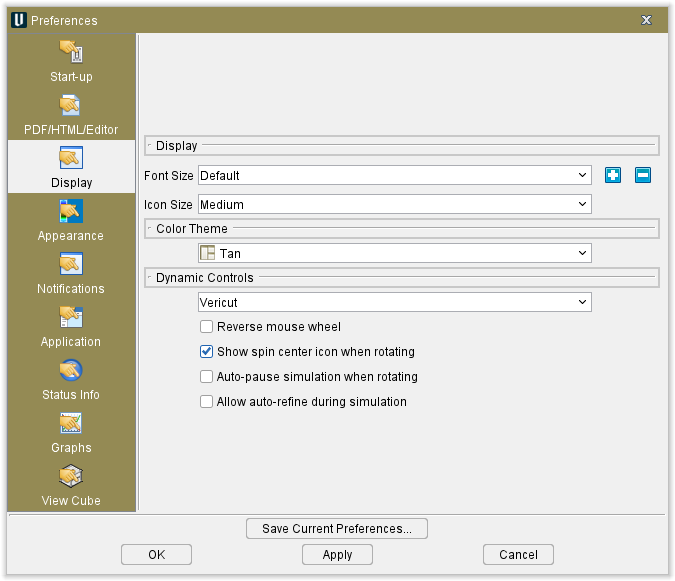
Display tab
The features on the Display tab enable you to specify display characteristics (Font Size, Icon Size, Color Theme, Dynamic Controls and Reverse mouse wheel) that you want to use.
Display Features
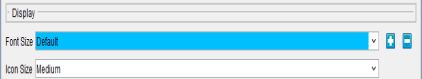
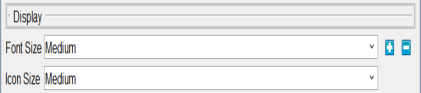
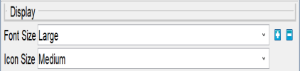
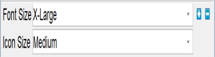
Font Size — The Font Size features enable you to change the size if the font for all text used in Vericut (menus, Vericut logger, windows, screen tips, etc.) Select the desired text size from the pull-down list. The following pictures show the difference text size displayed for each of the Font Size choices.
-
Default —
-
Medium —
-
Large —
-
X-Large —
![]() (Text Larger) — Use the Text Larger icon to make the text in Vericut menus, Vericut logger, windows, screen tips etc. larger. Each time you click on the Text Larger icon, the text gets incrementally larger to a maximum font size of approximately “24 point”.
(Text Larger) — Use the Text Larger icon to make the text in Vericut menus, Vericut logger, windows, screen tips etc. larger. Each time you click on the Text Larger icon, the text gets incrementally larger to a maximum font size of approximately “24 point”.
Max Font Size —
![]() (Text Smaller) — Use to make the text in Vericut menus, message logger, windows, etc. smaller. Each time you click on "Text Smaller", the text gets incrementally smaller to a minimum font size of approximately "6 point".
(Text Smaller) — Use to make the text in Vericut menus, message logger, windows, etc. smaller. Each time you click on "Text Smaller", the text gets incrementally smaller to a minimum font size of approximately "6 point".
Min Font Size —
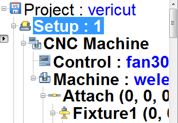
Icon Size — The icons used throughout Vericut are available in three different sizes. The following features enable you to select the icon size used in Vericut. A checkmark next to the feature indicates the current selection.
Icon Small/Medium/Large — Use this pulldown menu feature to change the size of the displayed icons. See below for a side by side comparison of icon sizes.
![]()
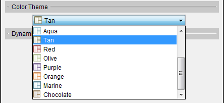
Color Theme
The Color Theme feature enables you to select a “favorite” color for the display of the Vericut Main window and dialogs. Select the desired color from the Color Theme pull-down list. Color Theme options include: light gray, gray, dark gray, Vericut light blue, Vericut dark blue, aqua, tan, red, olive, purple, Vericut yellow, marine, chocolate, dark mode, and gold.
Vericut Main Window
Sample Dialog
Dynamic Controls
The Dynamic Controls option enables you to use the same mouse actions while in Vericut, that are required to perform dynamic pan, zoom or rotate in each of the supported CAD systems. This parameter is saved in the Preferences file.
-
CATIA — Use the CATIA mouse action conventions for dynamic pan, zoom and rotate.
-
Creo — Use the Creo mouse action conventions for dynamic pan, zoom and rotate.
-
EdgeCAM — Use EdgeCAM mouse action conventions for dynamic pan, zoom and rotate.
-
GibbsCAM — Use GibbsCam mouse action conventions for dynamic pan, zoom and rotate.
-
hyperMILL — Use the hyperMILL mouse action conventions for dynamic pan, zoom and rotate.
-
MasterCAM — Use the MasterCAM mouse action conventions for dynamic pan, zoom and rotate.
-
NX — Use Siemens NX mouse action conventions for dynamic pan, zoom and rotate.
-
Power MILL — Use the Power Mill mouse action conventions for dynamic pan, zoom and rotate.
-
SOLIDWORKS — Use the SOLIDWORKS mouse action conventions for dynamic pan, zoom and rotate.
-
Top Solid — Use the Top Solid mouse action conventions for dynamic pan, zoom and rotate.
-
Top Solid 7 — Use the Top Solid 7 mouse action conventions for dynamic pan, zoom and rotate.
-
Vericut — Use the Vericut standard mouse action conventions for dynamic pan, zoom and rotate. See Dynamic Zoom, Pan and Rotate section of Vericut Help for additional information.
Reverse Mouse Wheel — Toggle On/Off to reverse the action of mouse wheel motion.
Show spin center icon when rotating — Toggle On/Off to display the spin center icon during rotations.
Auto-pause simulation when rotating — When toggled on (checked), causes the simulation to halt if you begin rotating displays in the Graphics Area.
Allow auto-refine during simulation — When toggled on (checked), Vericut will enhance visual representations in the Graphics Area during simulation.
Appearance tab
The features on the Appearances tab enable you to specify colors for graphically displayed design elements (fixtures, stock, design, and machine components) that you want to use.
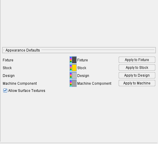
Appearance Defaults
Fixture — use this feature to set the display color for fixture elements.
Stock — use this feature to set the display color for stock elements.
Design — use this feature to set the display color for design elements.
Machine Component — use this feature to set the display color for machine component elements.
Allow Surface Textures — toggle this feature on (checked) to be able to apply surface finishes to models and components.
Apply to buttons — use the button on the same line as the element (for instance: Stock line and Apply to Stock button) to make the color show up in the graphics window immediately.
For all color selections, Use the  (Color Palette) icon next to each of the features to specify a color for the particular feature.
The right side of the (Color Palette) icon shows the current color for the feature. To change the color of the feature, click on the (Color Palette) icon to display the color palette window shown below.

Click on a color in the color palette window, to specify the new color for the feature. The color palette will close and the right side of the  (Color Palette) icon next to the feature will update to reflect the selected color.
To close the color palette window without changing the color, click on the  in the upper right corner of the color palette.
Notifications tab
The features on the Notifications tab are used to designate which email you would like to receive notifications and when you would like to receive them.
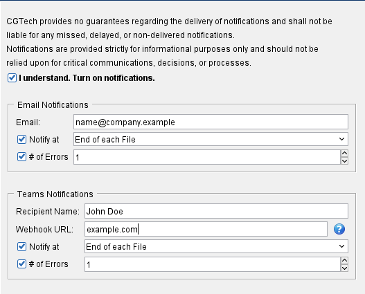
I understand. Turn on notifications. — Enables all other toggles on this window.
Email Notifications group
Email — Use this field to enter your chosen email address for receiving notifications.
Notify at — Toggle this feature on (checked) if you wish to receive notifications after every time the program is run. Then use the adjacent pulldown field to choose when notifications will be received. You can choose between End of each File, End of each Setup, or End.
# of Errors — Toggle this feature on (checked) if you wish to receive notifications after a specific number of errors have generated in the simulation. Then use the adjacent field to select the desired numbers of errors. You can either enter the desired number manually or use the arrows to incrementally increase or decrease the current set number.
Teams Notifications group
Recipient Name — Use this field to manually enter your Teams name.
Webhook URL — Use this field to provide your Teams app's specific url to be sure that only you are receiving the notifications. The adjacent ![]() button opens a Help page that explains how to find your Webhook URL if you do not know how to find one on your own.
button opens a Help page that explains how to find your Webhook URL if you do not know how to find one on your own.
Notify at and # of Errors both work identically to the same features described in the Email Notifications group.
Application tab
The features on the Application tab are used to select various default options for your software.
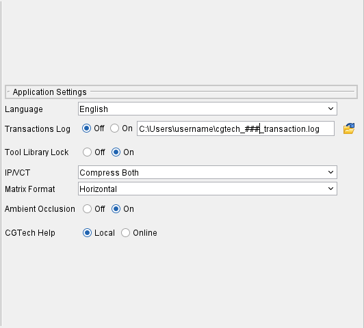
Language — Use this dropdown menu to specify which language you want the software to run in. Current options include: English, Chinese, Czech, French, German, Italian, Japanese, Korean, Portuguese, and Spanish.
Transactions Log — When toggled on (checked), this feature stores a complete log of your Vericut sessions in a location of your choice as designated via the location field to the right of the toggle. When toggled off (not checked), no log will be saved.
Tool Library Lock — When toggled on (checked), this feature locks tool library files to prevent manipulation. When toggled off (not checked), no lock will be applied.
IP/VCT — Use this pulldown field to change the amount of compression used for IP and VCT files. Options to choose between include:
-
No Compression — Turns off compression.
-
Compress IP Only — Applies compression to IP but not VCT files.
-
Compress VCT Only — Applies compression to VCT but not IP files.
-
Compress Both — Applies compression to both IP and VCT files.
Matrix Format — Use this pulldown field to change the layout of the matrix in the model position tap. Choose between Horizontal and Vertical layouts.
Ambient Occlusion — When toggled on (checked), approximates how bright light should be shining on specific surface parts.
CGTech Help — Toggle between accessing a Local saved copy of Vericut's Help documentation or an Online version that updates frequently.
Status Info tab
The features on the Status Info tab enable you to control the way the Status panel displays.
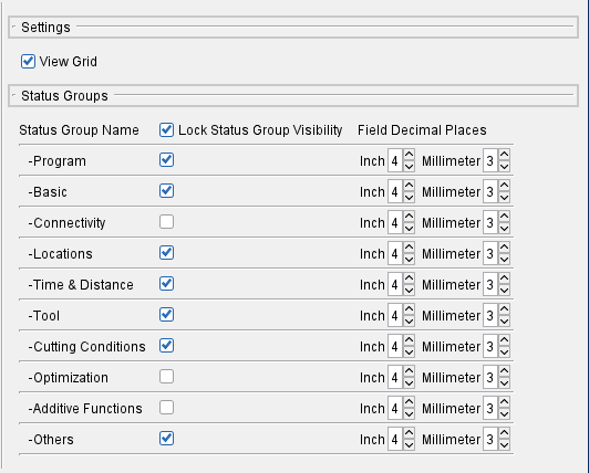
View Grid — This feature is on (checked) by default, the Status window data is neatly arranged into tables having visible grid lines. Turning this option off (unchecked) omits the grid lines to provides a more “spacious” Status window appearance.
Status Group Name — This column specifies the status group. This column cannot be edited.
Lock Status Group Visibility — Use the toggles in this column to control whether or the field is visible. More info about each of these Groups can be found in the Status Panel page of the Help.
Field Decimal Places — Use the fields in this column to control how many decimal places display for inch and millimeter measurements. By default, Vericut sets the display to 4 decimal places for both.
Graphs tab
The features on the Graphs tab enable you to activate various features of the Graphs panel by default.
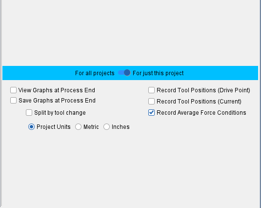
For all projects / For just this project — Use this switch to choose between applying your preferences globally or only to the current project you have loaded.
-
For all projects shows the graph preferences shared between all projects that also have this toggled, similar to the rest of the preferences in the other tabs.
-
For just this project shows only the graph settings for the currently opened project. When a project is saved, these settings will also be saved. They will not apply to other projects. This setting is toggled on by default.
View Graphs at Process End — When toggled on (checked), opens the Graphs window after Optimize Control has been applied and the simulation is run. This feature is available on all Modes except for Air Cuts Only.
Record Tool Positions (Drive Point) — When toggled on (checked), this saves tool positions to your .csv file which increases the file size but can be useful for certain projects. This adds “Driven Point” position and axis information columns to CSV output data.
Record Tool Positions (Current) — When toggled on (checked), this saves tool positions to your .csv file which increases the file size but can be useful for certain projects. This adds “Current” position and axis information columns to CSV output data.
Save Graphs at Process End — When toggled on (checked), saves the Graphs at the conclusion of simulation. This feature is available on all Modes except for Air Cuts Only.
Split by tool change — When toggled on (checked), Vericut saves individual CSV files for each tool that was analyzed or optimized. This option is available when "Save Graphs at Process End" is toggled on (checked). This feature is available on all Modes except for Air Cuts Only.
Record Average Force Conditions — When toggled on (checked), this saves force conditions to the .csv file. This option is toggled on by default.
Project Units — Select between metric and inches options to set which format units the Graphs window will utilize.
View Cube tab
The features on the View Cube tab enable you to turn the View Cube On/Off/, specify View Cube window size and View Cube color settings.
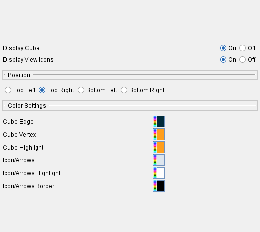
Display Cube — Use this feature to turn the display of the View Cube On or Off.
Display View Icons — Use this feature to turn on or off the display of the view icons that enable you to quickly switch between Workpiece, Machine, and Profile views. See View Attributes window for additional information on View Type.
Position — Use to select which corner of the Graphics Area the cube will appear in.
Color Settings — The Color Settings feature enables you to specify a color for each of the View Cube features described below.
Use the  (Color Palette) icon next to each of the View Cube features to specify a color for the particular feature.
The right side of the (Color Palette) icon shows the current color for the View Cube feature. To change the color of the feature, click on the (Color Palette) icon to display the color palette window shown below.

Click on a color in the color palette window, to specify the new color for the feature. The color palette will close and the right side of the  (Color Palette) icon next to the View Cube feature will update to reflect the selected color.
To close the color palette window without changing the color, click on the  in the upper right corner of the color palette.
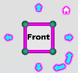
Cube Edge — Use this feature to specify a color for the View Cube’s edges as shown in the picture below.
Cube Vertex — Use this feature to specify a color for the View Cube’s vertices as shown in the picture below.
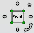
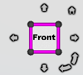
Cube Highlight — Use this feature to specify a highlight color for the View Cube’s edges and vertices. Holding the cursor over an edge or vertex will change the color of the entity to the highlight color so that you can see exactly which entity you are about to select as shown in the pictures below.
| Highlighted Edge | Highlighted Vertex |
|---|---|
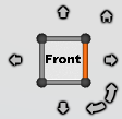 |
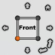 |
Icon/Arrows — Use this feature to specify a color for the View Cube’s icons and arrows as shown in the picture below.
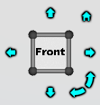
Icon/Arrows Highlight — Use this feature to specify a highlight color for the View Cube’s icons and arrows. Holding the cursor over an icon or arrow will change the color of the entity to the highlight color as shown in the pictures below. Notice how the Home icon is white because it is being hovered over while the arrows remain blue.
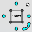
Icon/Arrows Border — Use this feature to specify a border color for the View Cube’s icons and arrows. Holding the cursor over an icon or arrow will change the color of the entity to the highlight color as shown in the pictures below.
![]()
Icon/Arrows Border — Use this feature to specify a border color for the View Cube’s icons and arrows. Holding the cursor over an icon or arrow will change the color of the entity to the highlight color as shown in the pictures below.
![]()
Putting it all together you get a View Cube window that looked like the picture below.