Edgecam-to-Vericut Interface (ECV)
Overview
The Edgecam Interface is a licensed software tool that facilitates the seamless transfer of manufacturing data from Edgecam to Vericut
Software Requirements: Edgecam Interface
Licensing Requirements
CGTech Licensing:
Edgecam Interface
Installation & Configuration: Edgecam Interface
Using an Installer
To install the Edgecam-to-Vericut Interface (ECV), download the latest Vericut Software Release and run the edgecam_interface_install.exe, then follow the step-by-step prompts to complete the installation.
You can download the installer from the Vericut website:
Request Latest Vericut Software Release
Environment variables: Edgecam Interface
To enable the Edgecam Interface to locate the necessary Vericut files, the following environment variables are available:
Environment Variables: Description & Example
CGTECH_INSTALL
Purpose: Defines the Vericut installation folder.
Example: For Vericut 9.7, set to: C:\Program Files\CGTech\Vericut 9.7
CGTECH_PRODUCTS
Purpose: Specifies the folder for the operating system running Vericut (windows64).
Example: For Vericut 9.7, set to:
C:\Program Files\CGTech\Vericut 9.7\windows64
LSHOST
Purpose: Defines the name of the license server computer.
Example: localhost
CGTECH_SINGLE_PLATFORM (Optional)
Purpose: Specifies if Vericut is running on a single platform.
Example: CGTECH_SINGLE_PLATFORM=YES
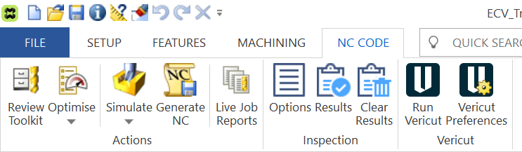
Set up a Vericut icon: Edgecam Interface
To access the Vericut Interface the Run Vericut ![]() and Vericut Preferences
and Vericut Preferences commands need to be added to the Edgecam Ribbon Bar.
Steps to add the Vericut commands to the Edgecam Ribbon Bar:
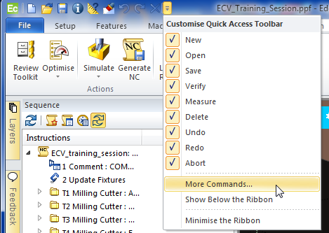
1. Select Customize Quick Access Toolbar > More Commands
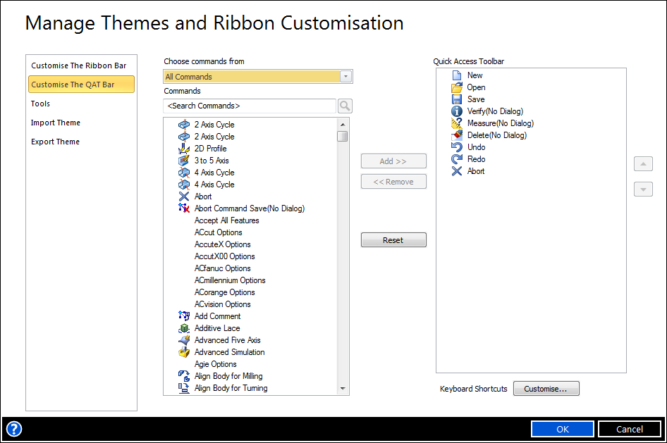
2. Select Customize The Ribbon...
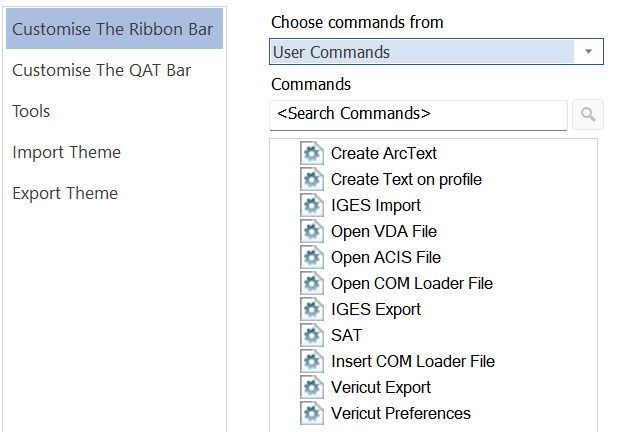
3. Select Choose commands from: > User Commands
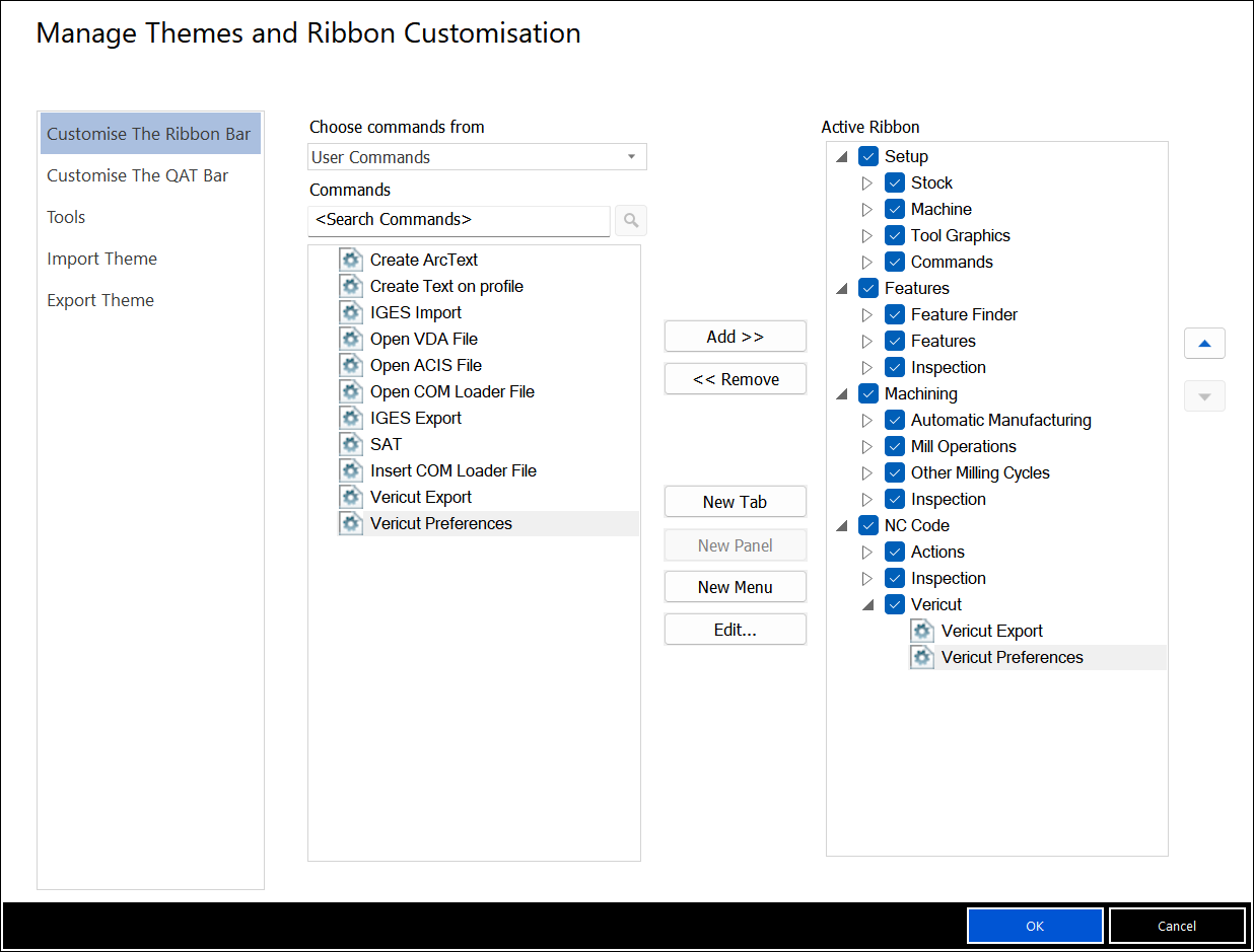
4. Select Active Ribbon > NC Code >
5. Select New Panel
6. Edit Name window > Name: Vericut
7. Select OK
8. Select Vericut Export from the Commands column
9. Select Add to move it to the Active Ribbon column
10. Do the same for Vericut Preferences
11. Select OK
12. From the Edgecam Ribbon, select Vericut Export, right mouse pick Edit Appearance
13. Button Text: Run Vericut
14. Button Image:
Browse C:\Program Files\CGTech\Vericut x.x.x\windows64\edgecam\version\icons\Vericut.ico
15. Check Always large image (32*32)
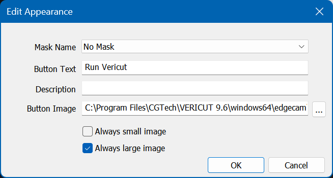
16. Select OK
17. Set up image for Vericut Preferences
18. Select OK
Microsoft Redistributables: Edgecam Interface
The Edgecam-to-Vericut Interface (ECV) may require the installation of Microsoft Redistributables, specifically the Windows C++ run-time libraries. These libraries ensure compatibility and proper functioning of the interface, allowing seamless data transfer between Edgecam and Vericut for manufacturing simulation.
Note: A runtime library is a collection of low-level compiler support routines and functions that are used by virtually all programs compiled with GCC (GNU Compiler Collection) and can be downloaded here.
Documentation: Edgecam Interface
Overview: The Edgecam interface exports manufacturing data from Edgecam to Vericut, ensuring a seamless transition for simulation. It automatically configures the necessary Vericut setup requirements and launches the software, ready to process.
Vericut Setup Requirements:
To run a successful session in Vericut, the following steps must be completed:
1. Select a VMC (Vericut Machine Configuration) – Define the machine setup for simulation.
2. Select and Orient Stock, Fixture, and Design Models – Ensure correct positioning of components.
3. Select NC Programs & Subroutines – Load the necessary machining programs.
4. Define Cutting Tools – Specify the tools used in the machining process.
5. Define Work Offsets Tables – Configure coordinate systems for accurate machining.
Accessing the Edgecam-to-Vericut Interface
Overview
The Edgecam-to-Vericut Interface consists of two windows:
Run Vericut ![]() window and Vericut Preferences
window and Vericut Preferences window
Run Vericut: This window contains features that enable you to specify settings needed by the Edgecam-to-Vericut Interface to export a specific Edgecam part and associated machining data to a Vericut project file, save the settings and then run the project file in Vericut.
Vericut Preferences: This window contains features that enable you to specify how you want the Vericut window to be displayed and specify a list of Project Template files and a list of Setup Template files that will be displayed and available for selection in the Vericut window. It also contains features that enable you to specify what features that you want displayed in the Vericut window and what the default values for those features should be.
To activate the Vericut Interface, select Run Vericut ![]() icon from the ribbon
icon from the ribbon
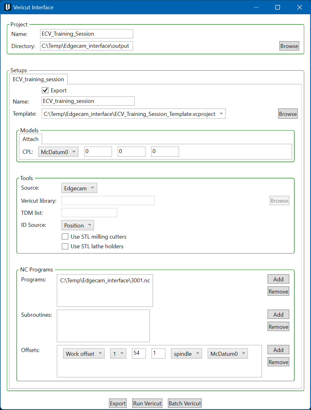
When you trigger ECV, you should see a window similar to this:
Important Note:
The Edgecam interface requires an active NC Manufacturing file to function properly with Vericut.
License Handling
- The interface checks out a license when opened.
- The interface checks in the license when closed.
Project
The Project section contains settings that apply to the entire project.
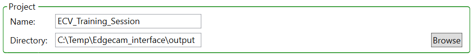
Name: Use to specify the name of the Vericut project file to be exported. The project name will appear in Vericut, is used for the names of exported files, and may be used for the output directory. Enter the name for the Vericut in the text field. The default project name is the name of the Edgecam part.
Directory: Use to specify the full path to the output directory that files for the Vericut project will be written to. Enter the full path in the text field or click on the Browse button and use the Browse for Folder window that displays to specify the path to the output folder. The default value is built from values specified in the Vericut Preferences window.
Note: The directory will be created if it does not already exist, but the parent directory must already exist.
Tip: In both the Run Vericut window and the Vericut Preferences window, holding the cursor over many of the features will display a short description of what the feature is used for. For features with a text box, hold the cursor over the text box. For features with a check box, hold the cursor over the feature’s label. For features that use a pull-down list, hold the cursor over the pull-down list.
Setups
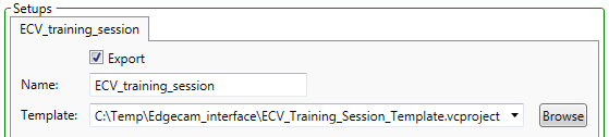
The tab heading is the name of the Edgecam sequence that these settings apply to. The name will be enclosed in a red box if any of the settings for the associated setup are not valid.
Export; When toggled on (checked), the setup will be exported to the Vericut project file. This is the default. When toggled off (not checked) the setup will not be exported. This condition is useful to enable exporting only those sequences that you are currently working on. At least one setup must be exported to the Vericut project file. When an Edgecam part contains only one sequence, and thus one setup, the export checkbox is automatically toggled on checked but is not be displayed except when you are in Full display mode.
Name: Use to specify the name of the Vericut setup. The setup name will appear in Vericut, and is used for the names of some exported files. The name can be modified in the Name text field. The default setup name is the name of the Edgecam sequence.
Template: A Template is an existing Vericut project file to be used for the current setup. The setup template file contains information used by Vericut to display and simulate the machine used for the current setup. Select the setup template from the pull-down list of templates previously specified in the Vericut Preferences window that matches the machine used for the current sequence. If the appropriate setup template is not found in the pull-down list, click on the Browse button and use the Setup Template file selection window to specify the setup template. The setup template is always displayed if there is no default template, or if there is more than one template to choose from.
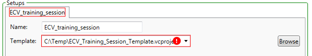
Invalid Settings in the Vericut window: When a setting in the Vericut window is not valid, it will be enclosed in a red box and a white exclamation mark in a red circle will be displayed. If the invalid setting is in the Setups section of the Vericut window, the tab showing the setup name will also be enclosed in a red box. I the case where there are multiple setups, all setups that have invalid settings will have the tab showing the setup name enclosed in a red box. See the picture below. If you hold the cursor over the enclosed area, an explanation of the problem will be displayed as shown in the picture below.
Making Multiple Selections in the Edgecam-to-Vericut Interface: To select multiple objects in the Edgecam-to-Vericut Interface, try these techniques:
Select multiple files in sequence: Click the first object in the sequence, then press and hold the
Select additional individual files: Press and hold the
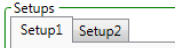
The Setup features are applicable to a specific setup. An Edgecam part can contain one or more sequences. For each sequence in the part, a Vericut setup will be written to the Vericut project file.
The settings for each setup are displayed on a separate tab. The tab heading is the name of the Edgecam sequence that these settings apply to. Click on the tab to change to a different setup.
Models
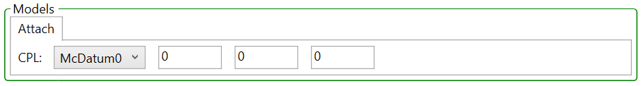
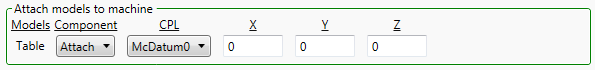
Attach models to machine: This section specifies how stock, fixture, and design models for the Edgecam part are to be attached to the Vericut machine. The resulting project file will direct Vericut to transform the Edgecam models so that the attach CPL is aligned with the attach component (same position and orientation) of the machine.
Attachments for Milling
Note: For Milling Attachments, the Interface only supports 1 Attach Component, the models from Edgecam will be exported to the first Attach Component found in the Vericut machine file.
Attachments for Turning
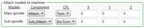
Models: The group of stock, fixture, and design models that this attachment applies to. The possible values are: - Table: - Models attached to the table in milling. - Main spindle: - Models attached to the main spindle in turning. - Sub-spindle: - Models attached to the sub-spindle in turning.
Component: The name of an attach component in the Vericut machine file that the stock, fixture, and design models should be aligned with. Only displayed when there is more than one attach component in the Vericut machine file.
CPL: A CPL from the Edgecam part. For milling the default attach CPL is the Edgecam mating CPL when available; for turning the default attach CPL is the spindle CPL. Otherwise a CPL whose name matches the name of the Vericut attach component, possibly followed by the name of the sequence is chosen.
X, Y, Z: The X, Y, and Z offsets from the attach component in the Vericut machine file to the point where the Edgecam stock, fixture, and design models will be aligned. The default is taken from the Edgecam mating offset when available, otherwise all three coordinates default to zero.
Coordinate Systems: CPLs in an Edgecam part are transferred to a Vericut project as coordinate systems, which are hidden until the user selects them in the Vericut View Axes dialog. For each setup, only CPLs which are referenced either in the corresponding Edgecam sequence, or by a G-Code offset in the Edgecam- Vericut interface for that setup, are transferred to the Vericut project.
Geometric Models: The Edgecam- Vericut interface transfers the geometric models for stock, fixtures, and design for the part in Edgecam to the Vericut project.
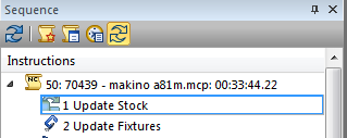
Stock: All stock models are output to all setups. Note that the Edgecam- Vericut interface does not consider which fixtures are removed by an Update Stock instruction.
Fixtures: Only active fixtures are output to a setup. An active fixture is one which has been added by an Update Fixture instruction in the corresponding sequence. Note that the Edgecam- Vericut interface does not consider which fixtures are removed by an Update Fixture instruction.
Design: Edgecam only supports one design model, which is output to all setups.
Tolerances for Geometric Models:
Parametric models: These are generated by the Edgecam- Vericut interface from parametric data provided by Edgecam. A fixed tolerance is used to generate these models. Because these models are typically small, no significant performance advantage would be gained by using a
coarser tolerance.
Non-Parametric models: These are generated directly by Edgecam as STL files, using the Output Tolerance field specified in the Edgecam Machine Parameters dialog for the sequence.
Model Tolerance: The tolerance of stock and fixture models can be controlled through the Edgecam GUI, but the tolerance of other STL models cannot be changed. The STL models are generated by Edgecam, and Edgecam does not provide an API to allow our interface to control the tolerance of the STL models.
The tolerance for a target STL model is fixed at 0.01mm. The tolerance for tool and holder STL models is taken directly from the source model. The tolerance for stock and fixture models can be controlled through the Edgecam GUI under File > Preferences > General > Tolerances > Display.
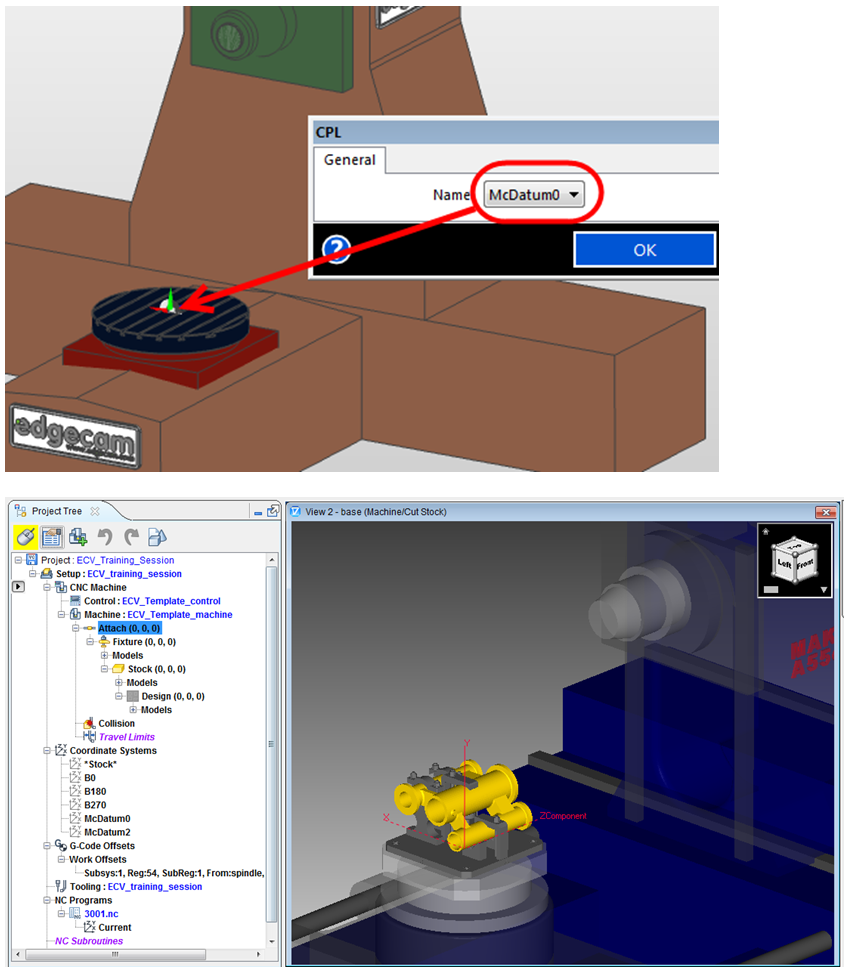
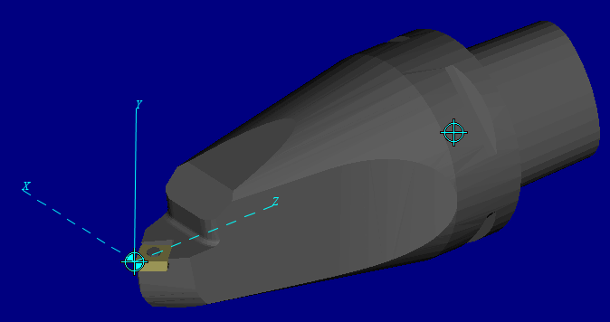
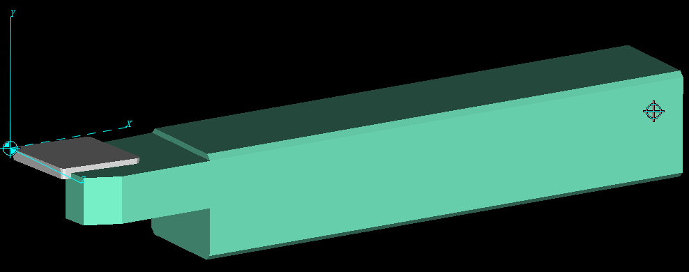
The Stock, Fixture and Design models will be positioned from the “Attach CPL” to the Vericut Component “Attach” as shown below. The McDatum0 CPL represents the Vericut Attach component location in Edgecam.
Tools
This section contains settings that control where the tools for the tool library of the current setup are extracted from.
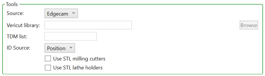
Source: Use the Source pull-down list to specify the where tool information should be obtained from. Choose one of the following:
- None: No tools will be exported.
- Edgecam: Tools will be extracted from the Edgecam part file.
- Vericut: Tools will be taken from the specified tool library.
- Merge: Tools will be extracted from both the Edgecam part and the specified Vericut tool library.
- TDM: Tools will be extracted from the specified Tool Data Management (TDM) tool list.
Vericut library: This feature is only active when Source is set to Vericut or Merge. Enter the path/filename of the Vericut tool library file in the text field or click on the Browse button and use the Vericut Tool Library file selection window that displays to specify the path/filename.
TDM list: This feature is only active when Source is set to TDM. Enter the name of the TDM tool list to be used, when generating tools for the exported Vericut setup, in the TDM text field.
ID Source: Specifies what to use as the ID for tools:
- Position: Use the position of the tool in the turret.
- Description: Use the description of the tool, or the comment if the description is empty.
- Comment: Use the comment for the tool.
Use STL milling cutters / Use STL lathe holders: Use to specify whether or not STL models will be used for the holders of milling or turning tools. When toggled on (checked) and STL models are available in Edgecam part file STL models are exported. When toggled off (not checked) or STL models are not available in the Edgecam part file parametric models are exported.
Note: X Gauge, Y Gauge and Z Gauge values are exported from Edgecam to the Vericut Tool Manager > Gage Point field
NC Programs
The NC Programs features enable you to add or remove NC programs, NC Subroutines, and G-Code offsets to be used for the current setup. This section is always displayed regardless of the Display mode set in the Vericut Preferences window.
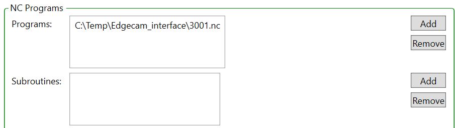
Programs: Use to specify the NC program files to be used for the current setup.
Subroutines: Use to specify the NC Subroutine files to be used for the current setup.
Add Selecting the Add button displays the file selection window enabling you to add file(s) to the list.
Remove After highlighting one, or more, files in the list, select the Remove button to remove the selected file(s) from the list.
Offsets
Optional list of G-Code offsets. The features in this section enable you to define Work Offset tables used to define the NC program origin. Available tables are Program zero, Work offset, and Base work offset
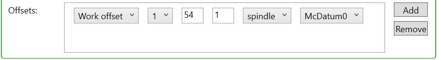
Table name for offset: Select the table name for the offset from the pull-down list. The following tables are available:
Program zero: The Program Zero table is used to specify the programmed zero location of a G-Code NC program file taking Tool Length Compensation into consideration.
Base work offset: The Base Work Offset table is used to specify the location from which work offsets are based.
Work offset: The Work Offsets table is used to store the work coordinate system offset (fixture offset) values. Note: A Work offset must be defined.
Vericut subsystem: Select the Vericut subsystem from the pull-down list.
G-code register number: Enter the G-Code register number in the text field. This field is only active when G-Code offset type is set to Program zero and Work offset.
G-code subregister number: Enter the G-Code subregister number in the text field. This field is only active when G-Code offset type is set to Work offset.
From component: Select the component that represents the "from" point for determining the offset from the From component pull-down list. Vericut will use the origin of the specified component.
To coordinate system: Select the coordinate system name that represents the "to" point for determining the offset from the To coordinate system pull-down list. The coordinates of the coordinate system origin are used as the "to" point.
Tip: Hold the cursor over any of the information fields in the offset record for information about what the field represents.
Add: Use this button to add G-Code Offset records in the Offsets list
Remove: After highlighting one, or more, G-Code Offset records in the Offsets list, select the Remove button to remove the selected G-Code Offset records(s) from the list.
Note: Select between the information fields or an inactive field to highlight the record. See Making Multiple Selections in the Introduction to the Edgecam-to-Vericut section above for additional information.
Vericut Preferences
The Vericut Preferences dialog shown allows control over the default values for the export settings, and over which settings are displayed by the Run Vericut dialog. These preferences apply to all Edgecam parts. The preferences need to be setup when the Edgecam-Vericut interface is installed, and typically do not need to be edited often. Customers need not be aware of the preferences if they are setup by customer support.
Options
The project section controls preferences for settings that apply to an entire project.
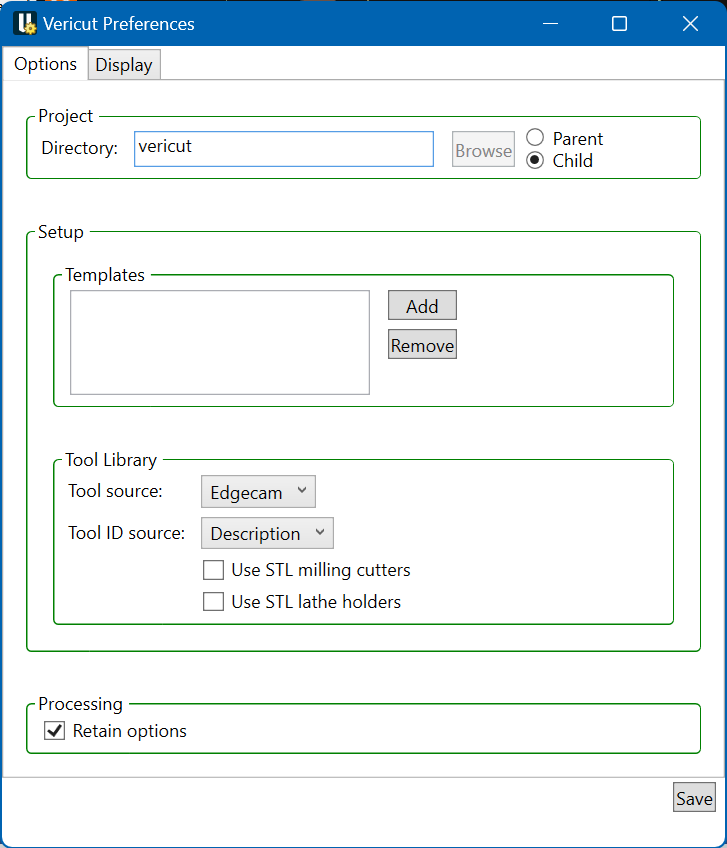
Directory
Specifies the part of the default value for the output directory. The full path of the output directory is built from two parts, a parent and a child, which are combined to form the path parent/child. If the Parent box is checked, then the value specified is used as the parent and the Edgecam part name is used as the child. If the Child box is checked, then the value specified is used as the child and the directory of the Edgecam part is used as the Parent.
Setup
The setup section controls preferences for settings that apply to each setup of a project.
Templates
Specifies a list of Vericut project files that can be used as setup templates. The field to left of each filename specifies which machine (really the name of the post-processor file for a machine) that the template can be used with. A single project file can be used with multiple machines by adding a separate entry in the list for each machine. The Vericut dialog will present only those templates that match the machine for the current setup.
Tool Library
Specifies default settings for the tool library settings.
Tool Source: Use the Source pull-down list to specify the where tool information should be obtained from. Choose one of the following:
- None: No tools will be exported.
- Edgecam: Tools will be extracted from the Edgecam part file.
- Vericut: Tools will be taken from the specified tool library.
- Merge: Tools will be extracted from both the Edgecam part and the specified Vericut tool library.
- TDM: Tools will be extracted from the specified Tool Data Management (TDM) tool list.
Tool ID Source: Specifies what to use as the ID for tools:
- Position: Use the position of the tool in the turret.
- Description: Use the description of the tool, or the comment if the description is empty.
- Comment: Use the comment for the tool.
Use STL mill holders / Use STL lathe holders:
Use to specify whether or not STL models will be used for the holders of milling or turning tools. When toggled on (checked) and STL models are available in Edgecam part file STL models are exported. When toggled off (not checked) or STL models are not available in the Edgecam part file parametric models are exported.
Retain options:
The “Retain options” check box, if you hover over the text you will see a tool tip “Retain project options between sessions.” If the box is checked (the default), any changes to the project options (i.e. the options for exporting the project) are written into the Edgecam part, and if the part is subsequently saved then the project options are also saved inside the part. If the part is exported again in the future, the project options are loaded from the Edgecam part before showing the dialog to the user. If the box is not checked, then the project options are not read from the part and the dialog will show the options as if the part had never been exported before. Any changes to the project options will not be saved into the Edgecam part.
Display
The display mode, along with a series of "Show" checkboxes, control which settings are displayed by the Vericut dialog Options
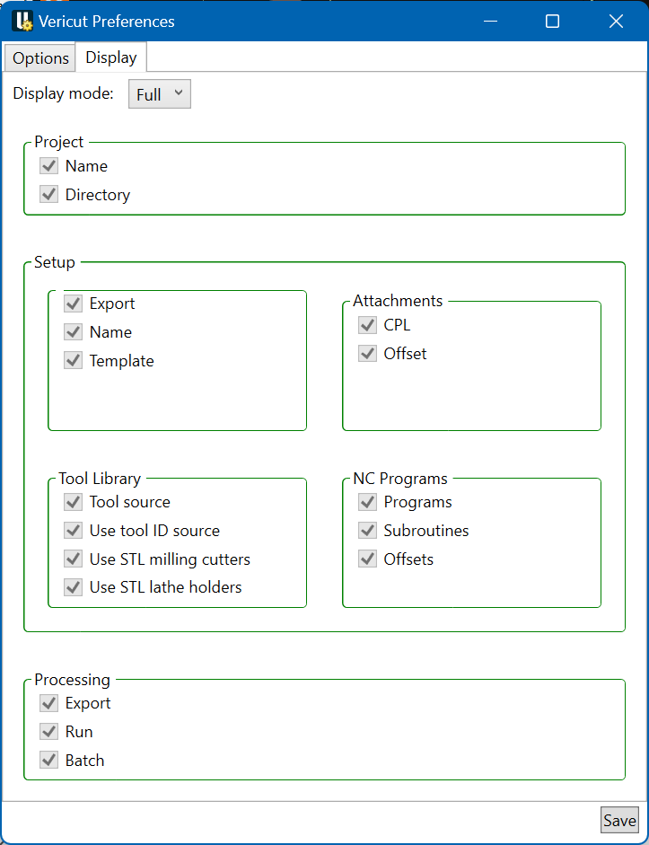
Display mode:
Minimal
Only necessary settings are displayed, ignoring the "Show" preferences.
Custom
Settings that are checked are displayed, along with all necessary settings.
Full
All settings are displayed, ignoring the "Show" preferences. While the Full mode is useful for becoming familiar with the Edgecam-Vericut interface, either the Minimal or Custom mode should be used in production. A setting is considered necessary if the current value is not valid, if no default is available, or if more than one valid default is available. The "Show" preferences control which settings are displayed in the Custom display mode.
Save
The processing section controls preferences for running Vericut
Generate buttons
The processing section contains settings that control how Vericut is run.
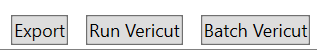
Actions:
The actions to be performed are determined by pressing one of the buttons in the bottom right corner of the dialog.
Export:
Saves the settings to the Edgecam part, and then exports the part to a Vericut project. Does not run Vericut.
Run Vericut:
Saves the settings to the Edgecam part, exports the part to a Vericut project, and then runs Vericut on the resulting project.
Batch Vericut:
Use to specify the how you want to run Vericut. Then toggled on (checked), Vericut will be run in batch mode. When toggled off (not checked), Vericut will be run in interactive mode.
Preferences
Preferences File Also known as 'prefs' file, stores all user specified 'global' settings for interface operation. The settings stored are called 'global' because they are responsible for overall look & feel and operational behavior of the interface. They are not tied to any specific Edgecam project.
By default, the 'Preferences' file is generated at:
C:\Users\username\AppData\Roaming\CGTech\Edgecam Interface
Example: