Configure Setup menu
Location:
Project Tree > Setup branch (Configure “on”)
The Configure Setup menu is used to set various features related to machining simulation and G-Code simulation.
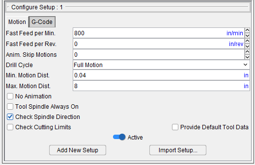
Motion tab — Features on the Motion tab enable you to provide important settings related to the motion displayed during the simulation, such as how often the display is updated (to reduce processing time), setting the minimum and maximum range of the Animation Speed slider, etc.
G-Code tab — Features on the G-Code tab provide important settings for G-Code simulation, such as: the G-Code programming method, when cutter compensation (CDC) codes are processed, NC program scanning, etc.
Active — When toggled "on" (checked), the setup is set as "active". When toggled "off" (not checked) the setup is set as "inactive".
Add New Setup — Add New Setup appends a new setup after the current setup. All settings from the current setup are copied to the new setup. Once the new setup is added, it becomes the current setup.
Import Setup — Opens the Import Setup window, enabling you to copy a setup from another project file and append it after the current setup.
Configure Setup menu, Motion tab
Location:
Project Tree > Setup branch (Configure “on”)
Features on the Motion tab enable you to provide important settings related to the motion displayed during the simulation, such as how often the display is updated (to reduce processing time), setting the minimum and maximum range of the Animation Speed slider, what checks are made during cutting.
Fast Feed per Min. — The maximum Feedrate which material should be removed (or added). Motions that remove (or add) material with feedrates exceeding this value are considered potentially unsafe because they could cause tool breakage, machine malfunction, part damage, or incorrect additive bead. Material removed (or added) under excessive feedrate conditions is shaded in the Error color (typically red) and causes a "Fast feed rate" error.
Fast Feed per Rev. — When in FPR mode and the Fast Feed (FPR) value is non-zero, the fast feed rate will be checked against the Fast Feed (FPR) value. Otherwise: The fast feed rate will be checked against the Fast Feed (FPM) value.
For Tapping and Threading, the fast feed will be checked against the Fast Feed (FPM) value. To apply multiple FPR fast feed values, set Vericut-MODAL FASTFPR = “X.X,” where “X.X” is the value you need to set.
📝 NOTES:
-
Tapping and Threading (although in FPR mode), will not use the FPR value because this setting is typically much higher than normal FPR settings.
-
The default for the Fast Feed (FPR) is zero. If zero, it will not be used allowing existing jobs to continue running.
- You can use the Vericut MODAL Record to set Fast Feed values.
Anim. Skip Motions — Use to specify the number of animated tool motions that Vericut should skip before updating the display. Enter "0" to display each tool motion. Enter a value between "1" and "1024" to represent the number of cuts to skip before display updates. Skipping cuts increases animation speed since the display is not constantly updated. The cut model is unaffected.
💡 Tip: You can also use the Animation Speed Slider to set, or modify, the Skip Motion value. See Animation Speed Slider in the Getting Started section of Vericut Help for additional information.
Drill Cycle — Controls when and how to simulate canned tool axis cycles (e.g. G8n, "CYCLE"). While Vericut simulates most popular cycle motions, there are also capabilities to add more and change how existing cycles are interpreted.
-
Ignore — Ignores cycle motions- the tool moves to each cycle position without performing cycle motions.
-
Bottom Only — Simulates cycle motions for a hole with one full depth motion- pecking or chip-breaking motions are not simulated.
-
Full Motion — Simulates all cycle motions, including pecking or chip-breaking motions.
-
No Motion — Processes drill cycles and displays material removal without any tool animation.
📝 NOTE: When the "Bottom Only" or "Ignore" options are used, certain motions (and checks) are ignored. This means that there will be no RAPID checks, no material removal, no limit checks, no collision checks, no redraws, etc. Because of its importance, checks related to "RAPID to the R-plane" motions are included when "Bottom Only" is selected, but not when "Ignore" is selected.
Need help troubleshooting cycle motion errors? For assistance with diagnosing error messages and conditions, contact Vericut technical support via our website, just click on the support link.
Min. Motion Dist. — Use to specify a minimum motion distance value to be used for defining the range of the Animation Speed Slider (ref. Animation Speed Slider in the Getting Started section of Vericut Help for additional information).
Vericut interpolates between the Min. Motion Dist. value, and the Max. Motion Dist. value, to determine the value of the Animation Speed Slider at the selected slide bar position. The Animation Speed value is expressed as a percentage of the total range.
Max. Motion Dist. — Use to specify a maximum motion distance value to be used for defining the range of the Animation Speed Slider (ref. Animation Speed Slider in the Getting Started section of Vericut Help for additional information).
Vericut interpolates between the Min. Motion Dist. value, and the Max. Motion Dist. value, to determine the value of the Animation Speed Slider at the selected slide bar position. The Animation Speed value is expressed as a percentage of the total range.
No Animation — Enables you to reduce processing time. When toggled "on" (checked), the graphics display is not updated until either processing is complete or you Stop the processing. At that time the cut model is displayed in it "final" state or the state that it was in when processing was stopped. You can also toggle No Animation on/off using the No Animation icon, ![]() , in the Vericut toolbar.
, in the Vericut toolbar.
Tool Spindle Always On — When toggled “on” (checked), Vericut will assume that the spindle is always on and will not check for spindle status (on/off) or output error messages related to cutting with the spindle off.
Check Spindle Direction — When toggled “on” (checked), Vericut check for spindle direction against the "valid" direction of the tool.
For turning tools, "valid" direction is based on the turning tool orientation. Spindle direction, (CW or CCW), is determined looking down the Z-axis of the spindle. It is assumed that revolving stock material should come onto the insert in the direction of positive Y-axis of the tool component. If spindle direction is wrong, or spindle speed is not defined, an error is reported to Vericut logger. Only one error per spindle is reported for each operation turning the spindle on or off.
The error is reported only if turning tool removes material from stock. For air moves, no errors are reported. Also, if an insert removes material in a motion that crosses the spindle Z-axis, no error is reported (in this case, one part of the insert is always on the correct side, while the other part is on the wrong side, therefore there is no preferable spindle direction).
For milling tools, the direction of the tool spindle (either spindle component or tool component attribute) is checked with the "valid" direction of the tool in the spindle. Tool spindle direction (CW / CCW) is defined looking down (negative Z) the tool axis. For revolved milling cutters, "valid" direction is based on the setting of Spindle Direction (clockwise or counterclockwise) in the tool definition. For inserted milling cutters, "valid" direction is based on the insert thickness direction.
If the direction of the spindle does not match the direction of the tool, then an error is reported whenever the tool removes material. The tool removes material in the error color (similar to the behavior for turning spindle direction error). The check is done and the error reported only when the tool removes material. Motion that does not remove material does not report an error.
The check is done for G-Code only.
Active — Toggle this feature on (slider to the right) to activate the setup. Toggle off (slider to the left) to deactivate.
Configure Setup menu, G-Code tab
Location:
Project Tree > Setup branch (Configure “on”)
Features on the G-Code tab provide important settings for G-Code simulation, such as: the G-Code programming method, when cutter compensation (CDC) codes are processed, and NC program scanning.
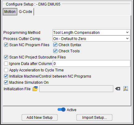
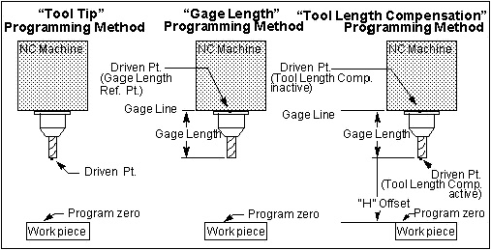
Programming Method — Describes the relationship between cutting tools and what is being driven by tool path file motion commands. (Take care NOT to describe the relationship between cutting tools and the driven point controlled by a CAM system.)
-
Tool Tip — XYZ values represent tool tip positions (center of the tool tip) at all times.
📝 NOTE: Tool length compensation codes (G43ZnHn/G49) do not appear in tool tip programmed tool paths. If these codes are present, use the Tool Length Compensation programming method. -
Gage Length — XYZ values represent gage point positions. The gage point is typically the spindle face, where the centerline of the tool intersects the machine gage line. Gage length values must be supplied using Gage Offset in Tool Manager, or via entries in a Gage Offset table.
-
Tool Length Compensation — With comp. active (e.g. G43ZnHn) XYZ values represent tool tip positions relative to program zero. With comp. cancelled XYZ values represent machine gage point positions relative to machine zero. Use an Input Program Zero table to describe where the part zero is. Vericut automatically calculates "H" offset values, or enters values in a Tool Length Compensation table. For proper tool loading on a 3-D machine supply gage offset values as described above for Gage Length programming method.
Process Cutter Comp. — This field determines whether or not we turn on Cutter Compensation “CDC” when specified in a program (for example: G41, G42). In addition, this field determines how we should default the “Cutter Comp Value” if it is not specified.
The “Cutter Comp Value” is the amount to adjust the toolpath (to the right or left) when CDC is active. For example: The program specifies to use Cutter Comp ID 4. The program will look for this ID in the Cutter Compensation table for the current Tool (See Tool Manager section for details). If it doesn’t exist, we can then either default the Cutter Comp Value to zero or to the full radius of the Tool.
📝 NOTE: The Cutter Comp Value is shown in the Status window in the “Others” section.
Options:
-
Off — Do not turn on CDC when specified and default the Cutter Comp Value to zero if ID is not found.
-
On – Default to Zero — Turn on CDC when specified, and default Cutter Comp Value to zero if ID is not found.
-
On – Default to Full Radius — Turn on CDC when specified, and default the Cutter Comp Value to full radius if not found.
📝 NOTE: The On/Off feature only applies to CDC. It does not apply to the compensation that occurs with Milling Pocket Cycles.
📝 NOTE: The resulting Cutter Comp Value is used by both CDC and Milling Pocket Cycles. See also the macro: CycleMillPocketToolRadiusLogic.
This GUI option can be overridden with the ProcessCutterComp macro.
The ProcessCutterComp macro will be disabled if “Disable ProcessCutterComp” is turned on within the G-Code Outputs window.
Scan NC Program Files — When toggled “On” (checked), performs a "scan pass" on NC program files to identify jump destinations for looping-branching logic. NC programs with this type of logic must be scanned for proper simulation in Vericut. Vericut scans all main and sub-program files looking for branch destination points. Any program file that contains subroutines (the actual subroutine, not the call to the subroutine), IF statements, GOTO statements, While statements, FOR statements, DO statements, REPEAT statements, CASE statements, or any other type of branch statements need to be scanned. This means all subroutine files will be scanned regardless of their content.
Check Syntax — When toggled “On” (checked), Check Syntax automatically runs at the start of processing.
Check Tools — When toggled "On" (checked), Check Tools scans for tools that are used but have not been defined. If a tool list exists, the tool found in the NC program will be cross referenced using that list. An error message will be produced for each undefined tool. This feature is toggled off (unchecked) by default.
📝 NOTE: This check is only done when the programs are scanned.
📝 NOTE: If the tool change is done within a subroutine, then along with M6 calling the tool change subroutine, M6 should also call the macro ToolChange OT=REPORT. This will allow this feature and the “Build Tool List” feature to work. See also: ToolChange2 OT=REPORT
Scan NC Project Subroutine Files — When toggled “On” (checked), Vericut will scan NC Project Subroutine Files. This is the default in order to maintain compatibility with existing jobs. When toggled "Off" (not checked), Vericut will not scan NC Project Subroutine Files.
📝 NOTES:
- Vericut will still scan the machine and control subroutine files.
- It is only valid to toggle this field Off when the file contains no branching (IF, DO, FOR, WHILE, GOTO, ...) and the name of the subroutine is the same as the name of the file.
Ignore Data after Column — When toggled "On"(checked), specifies the G-Code data column number to begin ignoring remaining data in the block. Use this feature when unmarked comments are permitted in designated columns of the G-Code data. Enter the number of the last valid G-Code data column in the text field next to this feature.
Apply Acceleration to Cycle Time — When toggled "On", uses the Accel/Decel parameters, as set on the Accel/Decel tab in the Configure Component menu for Component Type: All Motion Axes (ref. Accel/Decel tab in the Configure Component menu, Component Type: All Motion Axes section of Vericut Help) when calculating the Time value displayed in the Status window.
Initialize Machine/Control between NC Programs — Enables you to specify whether or not to reset the control's states, variables, etc. between NC program files during processing. When toggled "On" (the default), Vericut resets these values between NC program files. This condition is consistent with prior releases. Toggle "Off" to retain these values between NC program files.
Machine Simulation On — When toggled "On", simulates machine tool motions when a 3-D machine is displayed in a machine view.
Initialization File — Use this feature to specify the Setup Initialization File to be used. A Setup Initialization File is a text, or subroutine, file used to initialize variables used in the setup. The Setup Initialization File is processed at the same time as the "Start of Processing" event.
Click on the  (Add Setup Initialization File) icon to display the Setup Initialization Files file selection window and use it to specify the \path\filename of the Setup Initialization File to be used.
Use the ![]() (Clear Setup Initialization File) to clear the Initialization File text field.
(Clear Setup Initialization File) to clear the Initialization File text field.
Use the ![]() (Edit Setup Initialization File) to open the specified Setup Initialization File in a text editor window (ref. Text File in the Machine/Control tab section of Vericut Help for information on the text editor's features) to enable viewing and/or modifying it.
(Edit Setup Initialization File) to open the specified Setup Initialization File in a text editor window (ref. Text File in the Machine/Control tab section of Vericut Help for information on the text editor's features) to enable viewing and/or modifying it.
See Variables panel section of Vericut Help for information on monitoring and tracking Setup Variables.
See Initialization File in the Getting Started section of Vericut Help for additional information on Initialization Files.