Feature/History
Location:
X-Caliper tab > Feature/History group >  ( Feature/History )
The Feature/History command button is used to display related cut feature (mathematical description) and NC program history. The historical data includes: NC program file name, record number, and NC program record text responsible for cutting the feature. This function is useful to spot-check machined features, and determine the source of an error cut or additive bead placement identified in red by Vericut.
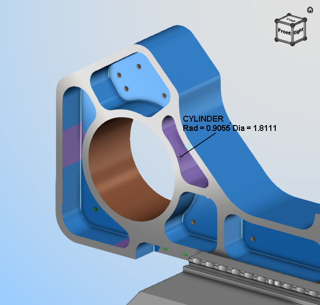
When using the Feature/History command button, simply click on any surface to gather data which will be displayed on the model with text and a leader as shown below:
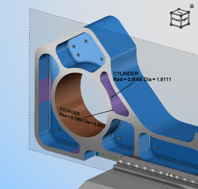
Left mouse button on the text displayed in the View and there are options to toggle on the display of other information on that feature:
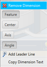
The text displayed in the View for Feature/History features can be oriented using Show Annotation Plane functionality in the X-Caliper Dimensions group to place the text on a plane.
The information for that feature is also display in the Vericut Logger panel as shown below:
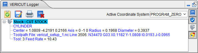
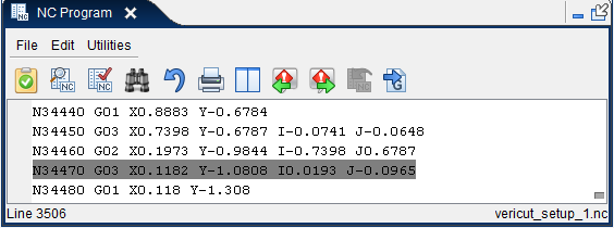
The Tool Path section of the record displays the name of the NC progam and which line of code in the NC program where the feature was created or cut. If the NC Program panel is open when you create the X-Caliper record, the line of code in the NC program is automatically highlighted. If the NC program panel is opened after the X-Caliper records was created, selecting or highlighting any section of a logged record will simultaneously highlight the line of code in the NC Program panel where the feature was created or cut as shown below:
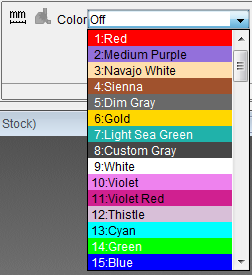
Color — The Color pull-down list appears in the X-Caliper Settings group when Feature/History is selected; it enables you to view the entire cut or additive path that created the selected feature in the selected color. To activate the Color option, select one of the colors from the pull-down list. When you select a feature in the graphics area, Vericut highlights the "history" (aka the cut) that created the feature with the selected color. To turn off the Color option, select "Off" from the pull-down list.
The following are geometric features identified by Vericut, listed alphabetically:
5-Axis Torus Sweep Surface — (Selection point, Normal vector) a surface cut by the corner radius of a bull endmill during a multi-axis "fanning", or NURBS motion.
Additive Stock — (Selection point, Normal vector) Uncut stock material that was deposited by an additive machining operation.
AUTO-DIFF model — (X, Y, Z value and surface normal) an uncut surface on a model displayed after an auto-difference Solid method comparison.
Circle — (X, Y, Z center, axis vector and radius) a surface cut by a circular motion.
Cone — (X, Y, Z center, axis vector and side angle) a hole bottom cut by an angle tip drill, corner cut by a tapered endmill, or chamfer cut by a turning operation.
Cylinder — (X, Y, Z center, axis vector and radius) an inside corner cut by 2 linear motions having an interior angle less than 180 degree, fillet cut by a bull or ball endmill moving perpendicular to the tool axis, or diameter cut by a turning operation.
Design Model — (Selection point, Normal vector) an uncut surface of a design model.
Diameter — (Center point, Axis vector, Radius, Diameter) a straight cylindrical diameter cut by a turning operation.
Ellipse — (X, Y, Z center, axis vector, major and minor focal distances) a ramping or plunging surface cut by the bottom of an endmill with a flat, or partially flat, bottom.
Elliptical Solid of Revolution — (X, Y, Z center, axis vector, tool, and NC program record) generated on the outward portion of a canted circle sweep.
Face — (Selection point, Normal vector) a flat machined surface left on the end of a part by a turning or grinding operation.
Fillet — (Center point, Axis vector, Minor Radius, Major Radius) a fillet left on a diameter by the radius of the cutter during a turning operation.
Fixture model — (X, Y, Z value and surface normal) generated on an uncut surface on a fixture model.
Helical Surface — (X, Y, Z center, axis vector, major radius, length of travel, number of rotations, NC program file, line number and NC program record, feed rate, and tool) a surface cut by a helical motion.
Holder Collision Area — (X, Y, Z value and surface normal) a holder/stock collision area cut stock model. Data also includes NC program file, record number and tool ID.
Plane — (X,Y,Z value and surface normal) a flat machined surface. Cylinders or circles cut using linear motions can also return this identity.
Profile Sweep — (Selection point, Normal vector) a surface cut by a non-rotating tool, such as a broach, defined via Profile model.
Ruled surface — (X,Y,Z value and surface normal) a surface cut by a multi-axis motion.
Sphere — (X, Y, Z center and radius) a surface cut by the end of a ball endmill.
Stock model — (X, Y, Z value and surface normal) an uncut surface on a stock model.
Taper — (Center point, Axis vector, Angle) a conic surface created by a turning tool moving at an angle along the turning axis.
Tapped Hole — (Right/Left Hand Thread identification, Center point, Major Diamater, Pitch) - threaded surface cut by a tapping operation.
Threaded Surface — (Right/Left Hand Thread identification, Selection point, Normal, Pitch) - threaded surface cut by a threading operation.
Torus — (X, Y, Z center, axis vector, major and minor radius) a fillet in a corner cut by a bull endmill, or fillet left on a diameter by the radius of the cutter during a turning operation.
Torus sweep — (X, Y, Z center, axis vector and major radius) This feature is typical of an angled (ramping or plunging) surface cut by a bull endmill.