Siemens NX-to-Vericut Drilling and Fastening Interface (NX2VDAF)
Overview
NX2VDAF is a licensed software program that provides a Siemens NX to Vericut Drilling and Fastening (VDAF) data transfer connection.
Software Requirements: Siemens NX VDAF Interface
Licensing Requirements
CGTech Licensing:
NX Interface
Installation & Configuration: Siemens NX VDAF Interface
User Configuration
No manual configuration required, The interface is pre-configured for seamless operation.
Installation Path
The interface installation files are located at:
C:\Program Files\CGTech\Vericut 9.6\windows64\nx2vdaf\NX_CR_version
To access version details, use:
C:\Program Files\CGTech\Vericut x.x.x\windows64\commands\nx_cr_version_2vdaf.bat
Environment variables: Siemens NX Interface
To enable the Siemens NX VDAF Interface to locate the necessary Vericut files, the following environment variables are available:
Environment Variables: Description & Example
CGTECH_INSTALL
Purpose: Defines the Vericut installation folder.
Example: For Vericut 9.7, set to: C:\Program Files\CGTech\Vericut 9.7
CGTECH_PRODUCTS
Purpose: Specifies the folder for the operating system running Vericut (windows64).
Example: For Vericut 9.7, set to:
C:\Program Files\CGTech\Vericut 9.7\windows64
LSHOST
Purpose: Defines the name of the license server computer.
Example: localhost
UGII_VENDOR_DIR
Purpose: Used to specify the directory where NX Interface files are stored.
Example: UGII_VENDOR_DIR=
C:\Program Files\CGTech\Vericut 9.7\windows64\nx\NX_CR_2212
CGTECH_SINGLE_PLATFORM (Optional)
Purpose: Specifies if Vericut is running on a single platform.
Example: CGTECH_SINGLE_PLATFORM=YES
Set up a VDAF icon: Siemens NX VDAF Interface
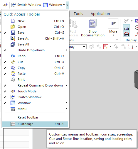
To add an icon to the Toolbar
If you wish to have an icon ![]() on an NX toolbar…
on an NX toolbar…
-
Select Toolbar Options
-
Customize
-
Search for VDAF
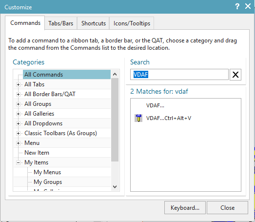
-
Drag and Drop command to desired location
-
Select Close
Microsoft Redistributables: Siemens NX VDAF Interface
The Siemens NX-to_VDAF Interface may require the installation of Microsoft Redistributables, specifically the Windows C++ run-time libraries. These libraries ensure compatibility and proper functioning of the interface, allowing seamless data transfer between Siemens NX and VDAF for manufacturing simulation.
Note: A runtime library is a collection of low-level compiler support routines and functions that are used by virtually all programs compiled with GCC (GNU Compiler Collection) and can be downloaded here.
Documentation: Siemens NX VDAF Interface
The Siemens NX-to-VDAF Interface (NX2VDAF) exports the Siemens NX models which represent the VDAF Skin, Structure, Fixture and design points to VDAF.
Accessing the Siemens NX VDAF Interface
To connect Siemens NX with VDAF, follow these steps:
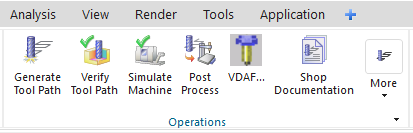
1. Use the VDAF icon
Select the VDAF icon from the Siemens NX ribbon
2. Alternately, you can hold down the Ctrl key, hold down the Alt key and click the O key
(Ctrl + Alt + O)
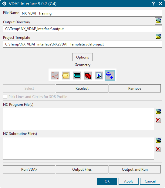
When you trigger NX2VDAF, you should see a window similar to this:
License Handling
- The interface checks out a license when opened.
- The interface checks in the license when closed.
Files
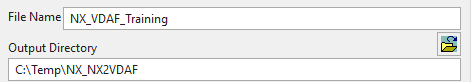
File Name — Enter the "base" name for Vericut Drilling and Fastening Simulation files that will be created. By default, the base name of the NX .prt file is used.
Output Directory — Enter the path to the directory where you want the Vericut Drilling and Fastening Simulation files output (.vdafproject, .tls. CGTPart.stk, CGTStock.stk), or use the "Browse" ![]() button to display a file selection window and use it to specify the path.
button to display a file selection window and use it to specify the path.
Project Template
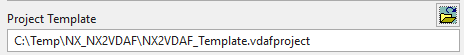
Project Template — Enter the /path/filename of the "template" .vdafproject file that you want loaded in the text field, or use the "Browse" ![]() button to display a file selection window and use it to specify the /path/filename. A "template" .vdafproject file is a previously defined Vericut Drilling and Fastening Simulation project file.
button to display a file selection window and use it to specify the /path/filename. A "template" .vdafproject file is a previously defined Vericut Drilling and Fastening Simulation project file.
Options
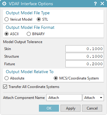
Output Model File Type — Use to specify the type of model files that are to be passed to Vericut Drilling and Fastening Simulation. Choose either Vericut Model (Vericut polygon file) or STL (Stereolithography model file).
Output Model File Format — Use to specify the file format of the model files. Choose either ASCII or Binary.
NOTE: "Binary" Vericut polygon files are platform specific.
Model Output Tolerance — Use to specify tolerance values for Skin, Structure and Fixture models.
Output Model Relative To — Model files are output relative to a specific coordinate system. Use to specify whether model files will be output to the Absolute or MCS/Coordinate System.
Absolute — This choice is typically used for CLSF files because the CL file MSYS record takes care of tool point location transformation. If Absolute is selected, the following is output in the setup file for this program group:
- Models are output relative to absolute.
- Vericut Process Matrix is turned-on.
- A Vericut Drilling and Fastening Simulation Csys is created for each MCS in each Program Group, attached to the Skin component.
MCS/Coordinate System — The MCS/Coordinate System choice outputs the models relative to the MCS of the first operation in the program group, or relative to the selected coordinate system (new), if one exists. This choice is typically used for G-Code processing since there is no MSYS equivalent in the G-Code data. It is sometimes used by CLSF users when they only have one setup, and want the models located relative to the MCS, rather than absolute. If MCS/Coordinate System is selected, the following is output in the setup file for this program group:
-
Models are output relative to the selected Program Group's MCS, or …
-
Models are output relative to the selected coordinate system.
-
Vericut Process Matrix is turned-off
-
A Vericut Drilling and Fastening Simulation CSYS is created for each MCS in each Program Group, attached to the stock component.
MCS/Coordinate System output is sometimes used for a single-position CLSF where the user wants the models in the same coordinates as the MCS.
Transfer All Coordinate Systems — When toggled "on" (checked), NX2VDAF transfers all NX coordinate systems to Vericut Drilling and Fastening Simulation.
Attach Component Name — Enter the name of the Vericut Drilling and Fastening attach component that is to be used for the current program group in the Attach Component Name text field or select it from the Attach Component pull-down list (described below).
Attach Component List — The Attach Component List contains a list of all Attach components available in the current Setup Template. Select the appropriate attach component from the pull-down list.
Geometry
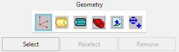
Geometry — By default, the NX2VDAF interface automatically selects models associated with your NC operations. However, the following options can be used to select alternate geometry to use in the simulation:
![]() (Skin) — Click this option to select geometry to represent the skin. Use the features in the Select Skin window to select the skin geometry. Use the Objects features to select geometry in the NX graphics. Use the Filters features to assist with the geometry selection. You can also enter the name of the appropriate skin geometry in the Select by Name text field located in the Other Selection Methods section of the window.
(Skin) — Click this option to select geometry to represent the skin. Use the features in the Select Skin window to select the skin geometry. Use the Objects features to select geometry in the NX graphics. Use the Filters features to assist with the geometry selection. You can also enter the name of the appropriate skin geometry in the Select by Name text field located in the Other Selection Methods section of the window.
![]() (Structure) — Click this option to select geometry that represents the skin. Use the features in the Select Structure window to select the structure geometry. Use the Objects features to select geometry in the NX graphics. Use the Filters features to assist with the geometry selection. You can also enter the name of the appropriate structure geometry in the Select by Name text field located in the Other Selection Methods section of the window.
(Structure) — Click this option to select geometry that represents the skin. Use the features in the Select Structure window to select the structure geometry. Use the Objects features to select geometry in the NX graphics. Use the Filters features to assist with the geometry selection. You can also enter the name of the appropriate structure geometry in the Select by Name text field located in the Other Selection Methods section of the window.
![]() (Fixture) — Click this option to select geometry that represents the fixture used to hold the skin/structure for the drilling and fastening operations. Use the features in the Select Fixture window to select the fixture geometry. Use the Objects features to select geometry in the NX graphics. Use the Filters features to assist with the geometry selection. You can also enter the name of the appropriate fixture geometry in the Select by Name text field located in the Other Selection Methods section of the window.
(Fixture) — Click this option to select geometry that represents the fixture used to hold the skin/structure for the drilling and fastening operations. Use the features in the Select Fixture window to select the fixture geometry. Use the Objects features to select geometry in the NX graphics. Use the Filters features to assist with the geometry selection. You can also enter the name of the appropriate fixture geometry in the Select by Name text field located in the Other Selection Methods section of the window.
![]() (Fastener Locations) — Click this option to select geometry that represents the fastener locations for the drilling and fastening operations. Use the features in the Select Fastener window to select the fastener locations geometry. Use the Objects features to select geometry in the NX graphics. Use the Filters features to assist with the geometry selection. You can also enter the name of the appropriate fastener locations geometry in the Select by Name text field located in the Other Selection Methods section of the window.
(Fastener Locations) — Click this option to select geometry that represents the fastener locations for the drilling and fastening operations. Use the features in the Select Fastener window to select the fastener locations geometry. Use the Objects features to select geometry in the NX graphics. Use the Filters features to assist with the geometry selection. You can also enter the name of the appropriate fastener locations geometry in the Select by Name text field located in the Other Selection Methods section of the window.
![]() (Datum Points) — Click this option to select geometry that represents the datum points for the drilling and fastening operations. Use the features in the Select Fastener window to select the datum point geometry. Use the Objects features to select geometry in the NX graphics. Use the Filters features to assist with the geometry selection. You can also enter the name of the appropriate datum point geometry in the Select by Name text field located in the Other Selection Methods section of the window.
(Datum Points) — Click this option to select geometry that represents the datum points for the drilling and fastening operations. Use the features in the Select Fastener window to select the datum point geometry. Use the Objects features to select geometry in the NX graphics. Use the Filters features to assist with the geometry selection. You can also enter the name of the appropriate datum point geometry in the Select by Name text field located in the Other Selection Methods section of the window.
About selecting geometry: In general, click the desired Geometry icon, then click Select and select the corresponding NX geometry. A window also displays containing standard NX "Class Selection" tools to assist you in selecting geometry. Geometry items can be selected in any order, for example: skin-structure-fixture, fixture-skin-structure, etc. NX highlights selected geometry. Selections for each of the geometry options can be re-selected or cleared by selecting the corresponding geometry option, then clicking Reselect or Remove, respectively. Reselect and Remove are only available when geometry was previously selected.
NOTES:
1. Non-solid models composed of surfaces, faces, etc. must form a watertight skin to be useful as solid models in Vericut Drilling and Fastening Simulation. If gaps or overlaps exist in NX geometry, the resulting solid may have holes, or portions (possibly all) of the model may fail.
2. All models transferred to NX2VDAF relative to the WCS. Pick Lines and Circles for SOR Profile — When toggled "on" (checked), this feature enables you to select connected lines and circles in NX which will be transferred into Vericut Drilling and Fastening Simulation as a Solid of Revolution (SOR). The lines and circles must lie in the XY plane of the WCS. They will be rotated around the Y axis of the WCS to create a Solid of Revolution (SOR).
NC Program File(s) & NC Subroutines File(s)
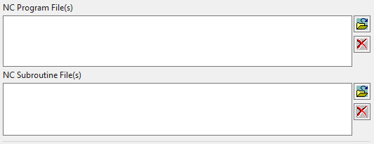
NC Program File(s): Displays a list of NC Program files that will be passed to VDAF. NC Sub Programs File(s): Displays a list of NC Sub Program files that will be passed to VDAF.
![]() Add — Use to add NC program/sub files to the NC Program/Sub Program File(s) list. When Select Existing NC Program is selected, NXV displays a standard file selection window enabling you to select existing files. When Automatically Output NC Program/Sub Program is selected, the configured NC code is output and added to the list.
Add — Use to add NC program/sub files to the NC Program/Sub Program File(s) list. When Select Existing NC Program is selected, NXV displays a standard file selection window enabling you to select existing files. When Automatically Output NC Program/Sub Program is selected, the configured NC code is output and added to the list.
![]() Remove — Use to remove the highlighted NC program file(s) from the NC Program File(s) list.
Remove — Use to remove the highlighted NC program file(s) from the NC Program File(s) list.
Generate buttons
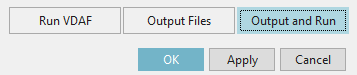
Run VDAF — launches Vericut Drilling and Fastening Simulation with the files created by Output Files.
Output Files — outputs all files, for all Program Groups, including the selected models, tool library files, updated project and setup files, and the "operations" file that assembles all of this information into a Vericut Drilling and Fastening Simulation "project" file.
See Operations File in the Getting Started section of Vericut Drilling and Fastening Simulation Help for information on the Operations File (or Ops File).
Output and Run — Use Output and Run to output the files needed by Vericut Drilling and Fastening Simulation and then launch Vericut Drilling and Fastening Simulation in the same step.
OK — Saves values that you set in the NXV windows as attributes the NX part file and closes the NXV Vericut window.
Apply — Saves values that you set in the NXV windows as attributes the NX part file and leaves the NXV Vericut window open to enable you to continue.
Cancel — Closes the NXV Vericut window without saving any of the settings in the NX part file.
Preferences
Preferences File
Also known as ‘prefs’ file, stores all user specified ‘global’ settings for interface operation. The settings stored are called ‘global’ because they are responsible for overall look & feel and operational behavior of the interface. They are not tied to any specific NX project. By default, ‘Preferences’ file is generated at C:\Users\username\nx2vdaf_version_user.prefs.
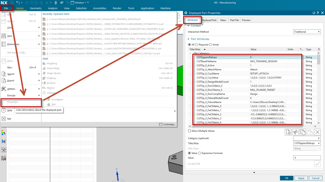
NX2VDAF Attributes
Values configured in the NX2VDAF dialog are stored directly within the NX part file. When the part is saved and subsequently reopened, these attributes values are automatically restored in the NX2VDAF interface.
NX stores part-specific attributes under the following menu path:
NX → File → Properties