CAD Model Converter
Location:
Utilities tab >  (CAD Model)
The CAD Model Converter converts (translates) CAD models in various formats to Stereolithography (STL) or Vericut Polygon model files. This converter is used to import complex castings, clamps, fixtures, and other 3-D design models into Vericut. Converted data can also be used with AUTO-DIFF to verify the machined part is as expected.
CAD model data can be converted interactively in Vericut (Utilities tab > CAD Model), via batch processing, or as a stand-alone utility outside of Vericut by running the CAD Model Converter "cad2v" command file located in the "commands" directory of your Vericut installation.
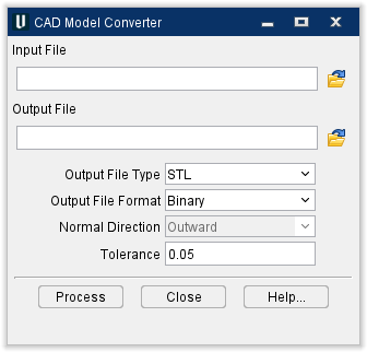
Input File — The name of the file containing the CAD data to be converted (CATIA V4, CATIA V5, STEP, SAT, CGR, 3DXML). Enter the /path/filename in the Input File text field or click on the  (Browse) icon to display the Select Input File file selection window and use it to specify the /path/filename.
Output File — The name of the file to receive the converted geometry. Enter the /path/filename in the Output File text field or click on the (Browse) icon to display the Select Output File file selection window and use it to specify the /path/filename.
Output File Type — The type of output file to be created. Options are: Vericut or STL.
Output File Format — The format of the output file. Options are: BINARY or ASCII.
Normal Direction — The direction in which surface normal vectors point, as viewed in the CAD system. Feature only applicable to Vericut output file types. Options: OUTWARD or INWARD.
Tolerance — Use to specify the amount of chordal deviation allowed in 3-D space from the CAD data when creating the converted surface. The converted surface is approximated using "facets", or triangles.
Process — Processes (converts) the CAD data according to the current window settings.
Close — Closes the CAD Model Converter window.
Help — Displays this Help page. (You can also use the F1 key to display this Help page.)