Configure Tooling menu
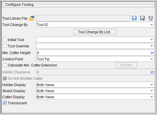
Tool Library File — The Tool Library File features enable you to open an existing, and save the current Tool Library file (ref. Tool Library Files section of Vericut Help). The /path/filename of the current Tool Library file is displayed.
 (Open File) — Use to open an existing Tool Library file. Use the file selection window that displays to select the desired Tool Library file. Most features on this window are standard file selection window features that enable you to navigate through directories, filter files, and type, or select, /path/filenames. A description of features specific to Vericut can be found in the Introduction to Vericut File Selection Windows in the Getting Started section of Vericut Help.
![]() (Save File) — Saves (updates) the current Tool Library file. Vericut will save the Tool Library file if you have sufficient permissions to save the file in its present folder. Otherwise, the Save Project File As window will display enabling you to specify a location to save where you have write permissions.
(Save File) — Saves (updates) the current Tool Library file. Vericut will save the Tool Library file if you have sufficient permissions to save the file in its present folder. Otherwise, the Save Project File As window will display enabling you to specify a location to save where you have write permissions.
![]() (Save As File) — Opens the Save As File window enabling you to save the current Tool Library file with a new name or in a new location. Most features on this window are standard file selection window features that enable you to navigate through directories, filter files, and type, or select, /path/filenames. A description of features specific to Vericut can be found in the Introduction to Vericut File Selection Windows in the Getting Started section of Vericut Help.
(Save As File) — Opens the Save As File window enabling you to save the current Tool Library file with a new name or in a new location. Most features on this window are standard file selection window features that enable you to navigate through directories, filter files, and type, or select, /path/filenames. A description of features specific to Vericut can be found in the Introduction to Vericut File Selection Windows in the Getting Started section of Vericut Help.
![]() (Tools) — Opens the Tool Manager window enabling you to create and maintain Vericut Tool Library files containing descriptions of cutting tools, or tool assemblies.
(Tools) — Opens the Tool Manager window enabling you to create and maintain Vericut Tool Library files containing descriptions of cutting tools, or tool assemblies.
Tool Change By — Controls how Vericut receives descriptions of cutting tools.
-
Cutter Desc. — Process parametric cutter descriptions in the NC program file. Examples: CUTTER and Vericut-TC comment records.
-
Vericut TC — Process by PPRINT/Vericut-TC cutter statements in the NC program file.
-
Tool ID — Process NC program records that reference tool or pocket numbers and retrieve associated tools from a Tool Library file. Examples: TnM6 (G-Code NC programs), LOADTL or LOAD TOOL, and TURRET. When using Tool Change by Tool Number, The tool number is matched with the pocket number (ex: tool #5 in pocket #5).
-
List — Processes tools by the lists they are a part of.
-
File Name — Tool changes are done by a tool from the current Tool Library file as specified for each NC program file in the list.
-
NX CLS Tool Name — This option is only applicable when NC Program Type is set to NX CLS. Tool Name refers to the tool identifier in the TOOL PATH/ statement in the NX CLS file.
Initial Tool — When toggled on (checked), Vericut loads an initial tool from the current Tool Library file. This action occurs automatically when the Project file is loaded, the NC program is rewound, or the model is reset. Choose the ID of desired tool from the Initial Tool pull-down list.
This feature is useful when simulating NC programs for machines that have a tool loaded at the time tool processing is started, and therefore do not have information about the first tool.
You can also use this feature to preload multiple tools in a milling machine (e.g. tool change carousel), via selecting Initial Tool, but leaving the corresponding field blank. If you specify a tool number, then that tool is forced in to all tool component positions.
📝 NOTES:
-
This feature should not be used if you are using multiple NC program files.
-
This action also occurs when a "Turret" type component is present, such as commonly used with turret lathe setups.
Tool Override — When toggled on (checked), Vericut overrides the current cutter description with a specified tool from the current Tool Library file. This action occurs immediately. Choose the ID of desired tool from the Tool Override pull-down list. Vericut uses the override tool until you select a different tool ID or clear the Tool Override checkbox. When cleared, the tool that would have been in use becomes the active tool.
Min. Cutter Height — Default height used when the current tool description does not specify height, or when specified height is less than this value. This feature only affects milling cutters.
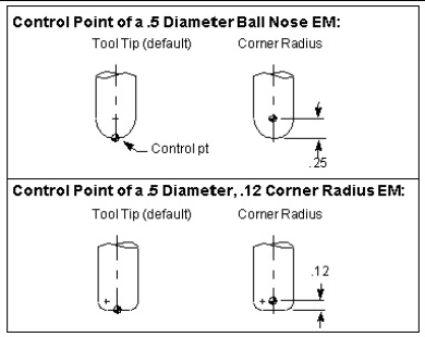
Control Point — Controls how milling tools are driven. By default, Vericut drives the tool tip. Material is removed based on NC program motion commands and the tool shape, relative to the control point. Options:
-
Tool Tip — Point located at the bottom-center of the cutter.
-
Corner Radius — Point located a distance equal to the cutter corner radius up from the tool tip. With ball nose end mills, this point is commonly referred to as the "ball center".
📝 NOTE: The Corner Radius option is only applicable to APT.
📝 NOTES:
-
If Corner Radius is used with non-ball nosed end mills, the offset is calculated along the tool axis, from the tool tip to the center of the first arc encountered in the tool profile. Corner Radius is only applicable to APT.
-
To specify a milling tool control point other than the tool tip or corner radius, define tools via the Tool Manager and specify a control point offset via the tool's Properties.
This feature is not applicable to turning tools. Instead, define tools via the Tool Manager and specify a control point offset via tool Properties.
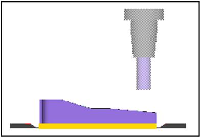
Calculate Min. Cutter Extension — When toggled on (checked), Vericut calculates the minimum height required to avoid shank/holder collisions with the stock and all fixtures in a Workpiece view, for standard Vericut.
📝 NOTE: This feature only applies to milling cuts. It cannot be used for turning cuts.
When toggled on, all holders move down to the bottom of the cutter. The first holder and any holders above it are processed independently, so one sees both the first and subsequent holders move down to the same location and the cutter will not be seen. As cutting starts, the holders move up as needed to avoid a collision with stock.
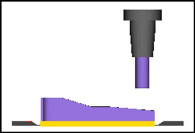
If potential holder collisions are detected during the simulation, Vericut extends the cutter to avoid the collision and adds this amount to the calculated height. The calculated extension amount is automatically applied to the existing Gage Point Z value.
📝 NOTES:
-
The calculated minimum cutter extension could end up being shorter that the cutter height defined in Tool Manager. If this is not acceptable, use the Do Not Shorten Cutter feature to prevent Calculate Min. Cutter Extension from calculating a minimum cutter extension value that is shorter than the cutter length defined in Tool Manager.
-
When these calculations are being performed, tool holder collisions are not reported since Vericut extends the cutter to avoid the collision.
If desired, you can include additional clearance in the calculation via specifying Holder Clearance. The final calculated height for each tool is displayed in the Log file Tool Summary section under the "Min" column heading.
Update — The Update button enables you to view and save tool values adjusted by Calculate Min. Cutter Extension at any time in the simulation. When simulating with Calculate Min. Cutter Extension toggled on (checked) pause the simulation at any time and press the Update button. Vericut will display all of the tools and their adjusted values that have been calculated to the current point in the simulation, in the Vericut Logger.
A message window will also display giving you the opportunity to save the adjusted tool values to the tool library file. Responding Yes will save the values to the tool library file and close the window. Responding No will close the window without saving.
In either case, press the Play button to resume the simulation and the calculation of Min.Cutter Extension values from the point that that you paused the simulation. You will be given the opportunity to save all of the adjusted tool values at the end of the simulation, the same as if you had not used the Update button.
Holder Clearance — Use to specify a clearance value to be added when calculating the minimum cutter extension (see above). The clearance value is also included in the Log file minimum height values.
📝 NOTE: This feature is only active when Calculate Min. Cutter Extension is toggled "On".
Do Not Shorten Cutter — This feature enables you to control the way that Calculate Min. Cutter Extension works. When toggled "on" (checked), Calculate Min.
Minimum cutter extension calculations begin with the cutter height defined in Tool Manager. If potential holder collisions are detected during the simulation, Vericut extends the cutter to avoid the collision and adds this amount to the defined height. Using this method prevents Vericut from changing the cutter height to be shorter than originally defined in Tool Manager.
Cutter Display — Use the Cutter Visibility features to specify whether or not cutters are visible, and in what views. A check indicates “visible” in the view. The setting applies to all cutter components in the setup.
-
Blank — Cutters are not visible in any view.
-
Workpiece View — Cutters are only visible in a Workpiece View.
-
Machine View — Cutters are only visible in a Machine View.
-
Both — Cutters are visible in any view.
Holder Display — Use the Holder Visibility features to specify whether or not holders are visible, and in what views. A check indicates "visible" in the view. The setting applies to all holder components in the setup.
-
Blank — Holders are not visible in any view.
-
Workpiece View — Holders are only visible in a Workpiece View.
-
Machine View — Holders are only visible in a Machine View.
-
Both Views — Holders are visible in any view.
Shank Display — Use the Shank Visibility features to specify whether or not shanks are visible, and in what views. A check indicates "visible" in the view. The setting applies to all holder components in the setup.
-
Blank — Shanks are not visible in any view.
-
Workpiece View — Shanks are only visible in a Workpiece View.
-
Machine View — Shanks are only visible in a Machine View.
-
Both Views — Shanks are visible in any view.
Translucent — When toggled "on" (checked), visible cutters and holders are displayed in translucent mode. When toggled "off" visible cutters and Holders are displayed in solid mode.
| Translucent mode | Solid mode |
|---|---|
 |
 |