View Orient window
Locations:
View tab >  (Orient)
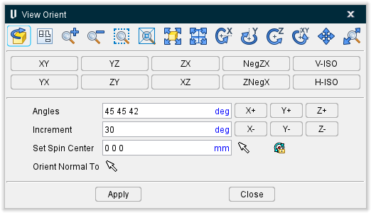
The Orient command button opens the View Orient window enabling you to orient the view, including: rotate, zoom, pan, reverse, etc. You can view machining from any angle or distance, and change the view at any time during the simulation. Views of the workpiece, NC machine are oriented in the same manner, as described by the sections that follow. In general, click in a view to make it active, then change view orientation as required. View rotations are described with respect to the "view coordinate system".
📝 NOTE: When accessed from the Tool Manager, View Orient window has identical functionality but orientation changes will be displayed in the Tool Manager window, Tool Display Area rather than the main window Graphics Area.
Dynamic Viewing Options:

These options use mouse actions to dynamically orient the object in view. Mouse actions are different, depending on the active option-see the table below for details. Dynamic viewing options are also available on the Vericut Toolbar.
| Toolbar Icon: | Name: | Action: |
|---|---|---|
| Reverse | Reverses viewing direction, as if you stood behind the object | |
| Snap to Orthogonal View | Snaps the current view to the closest orthogonal view. | |
| Zoom In | Zooms in by 20%. | |
| Zoom Out | Zooms out by 20%. | |
| Zoom to Box | Left-click and move mouse to trap area to zoom into (press <Esc> to interrupt rubber-banding) | |
| Zoom Box in New View | Similar to Zoom (standard mode) described above except a new view is created to display the zoomed area. | |
| Fit | Fits object in active view | |
| Fit All | Fits objects in all views | |
| Dynamic X Rotation | Horizontal rotation- drag mouse up/down in direction to rotate | |
| Dynamic Y Rotation | Vertical rotation- drag mouse left/right in direction to rotate | |
| Dynamic Z Rotation | Screen plane rotation- drag mouse left to rotate CCLW, right for to rotate CLW | |
| Dynamic XY Rotation | Horizontal/vertical combined rotation- drag mouse up/down/left/right in direction to rotate | |
| Dynamic Pan | Pan/translate- drag mouse in the direction pan | |
| Dynamic Zoom | Zoom/magnify- drag mouse up to zoom in, down to zoom out |
Use the following mouse features to manipulate the view with a single mouse button.
-
Dynamic Rotate — Left mouse button, drag.
-
Dynamic Pan — Right mouse button, drag.
-
Dynamic Rotation — Rotate the thumbwheel toward you to make the displayed image larger, away from you to make the displayed image smaller.
The following keys provide instant access from the keyboard to dynamic viewing options (press and hold keys while dragging):
-
Dynamic Zoom — <Ctrl>, drag
-
Dynamic Pan — <Shift>, drag
-
Dynamic XY — <Ctrl> + <Shift>, drag
Mouse actions are the same as described above.
↘️ Shortcuts:
-
You can quickly fit, reverse, or orient the model in one of the defined views by right-clicking in the view and then selecting Fit, Reverse, or Select View from the menu that displays.
-
Use the thumb wheel on the mouse to Zoom to Box. Click on the thumb wheel and drag the mouse to define the box to zoom to. The zoom takes place when you release the thumb wheel.
Standard drawing view buttons
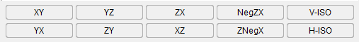
These buttons orient the object in the selected standard drawing view and automatically fits the object in the view.
Rotation Options:
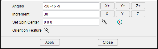
Angles — Absolute rotation about the view coordinate system X Y Z axes, respectively. The three values are separated by spaces.
Increment — Degrees of incremental rotation to apply when a rotation button is pressed (see below).
Rotation buttons (X+/X-, Y+/Y-, Z+/Z-) — axis and direction in which to apply incremental rotation specified by the Increment value.
Set Spin Center — Specify a point to be used as the center of rotation during dynamic rotations. Click in the Spin Center text field so that it becomes active, then either enter XYZ values (separated by spaces) in the field and click on the Apply button or click on a position on an object (not the background) in the view to specify the Spin Center point. The values are applied to the "active" view. If a workpiece view is the active view, the coordinates are relative to the origin of the workpiece coordinate system. If the "active" view is a machine view, the coordinates are relative to the origin of the machine coordinate system.
Press ![]() to display the Spin Center marker
to display the Spin Center marker  and activate the point for the active view. To de-activate Spin Center point, press the button again. You can specify a different rotation point for each view. When you close the View Orient window, the Spin Center markers will no longer be displayed but the activated Spin Centers will remain active. When you use one of the dynamic rotation features described above in a view with an active Spin Center, the Spin Center point will be used as the center of rotation instead of the view coordinate system origin.
↘️ Shortcut: You can quickly change the spin center location by right-clicking on the position on an object (not on the background) in the view where you want the spin center located, and then left-click on Spin Center in the menu that displays. The spin center will be located at your pick point.
Orient On Feature — Resets the view to the normal of the feature selected in the graphics area. The modified view is centered on the position of the selection vector. Click on the Orient on Feature button ![]() so that it becomes activated. Click on a feature in the Graphics window.
so that it becomes activated. Click on a feature in the Graphics window.
Apply — Use the Apply button to accept the current window settings and leave the View Orient window open for additional work.
Close — Use to close the View Orient window.
Rotate a View
You can rotate views of the workpiece or NC machine to provide optimum viewing. If a Spin Center point is active for a workpiece or machine view, it will be used as the center of rotation for dynamic rotations instead of the view coordinate system origin. Vericut offers several methods of view rotation, as described below.
View orientation does not change the orientation of the model in physical space, only the way that it is displayed in a Vericut view. To change the orientation of the model in physical space, use the Configure Model menu features, in the Project Tree.
To dynamically rotate a view:
-
Click in the view that you want to rotate so that it becomes the "active" view.
-
Use one of the following methods to rotate the objects in a view:
-
You can rotate specifically about the view coordinate system X, Y, or Z axis using the dynamic rotation icons
 in the View tab > Orient or in the Vericut Toolbar. Selecting the icon converts your mouse to the same image as the icon and allows you to click and drag the image along the rotational axis or axes that were selected. You can also access the dynamic rotation icons directly from the View tab.
 -
Press and hold the <Ctrl> + <Shift> keys while left-clicking and dragging the mouse in the direction to rotate. The model rotates in the direction you drag. Note that the speed of rotation varies with the complexity of the model.
-
To rotate a view by angle values (degrees):
-
Click in the view that you want to rotate so that it becomes the "active" view.
-
In the Vericut main menu ribbon click on View tab > Orient to display the View Orient window.
- In the View Orient window, use one if the following methods to rotate the objects in a view:
To enter view coordinate system X Y Z angles: enter the values for X rotation, Y rotation and Z rotation (separated by spaces) in the Angles text field and then press Apply.
For example, "0 0 0" specifies no rotation, or XY "plan" view. "-30 0 0" rotates 30 degrees in the negative direction about the view coordinate system X-axis.
To rotate incrementally by degrees: enter the number of degrees to rotate for each increment in the Increment text field, and then press the desired rotation axis/direction button: X+, X-, Y+, etc.
After a short delay, the view of the model is rotated. Repeat pressing the axis/direction buttons to rotate additional increments.
To rotate a model 180 degrees (reverse) in a view:
-
Click in the view that you want to rotate so that it becomes the "active" view.
-
In the Vericut main menu ribbon click on View tab > Orient to display the View Orient window.
- In the View Orient window, click on the Reverse button.
- You can also click on the
 (Reverse) icon In the Vericut Toolbar.
After a short delay, the view of the model is reversed.
To snap the current view to the closest orthogonal view:
-
Click in the view that you want to rotate so that it becomes the "active" view.
-
Orient the current view so that it is close to the orthogonal view that you want.
- Click on View tab > Orient to display the View Orient window.
- Click on
 and the view will re-orient to the exact orthogonal view.
Changing a View Rotation Point
You can change the center of rotation that will be used for a view during dynamic rotations to provide optimum viewing. By default, dynamic view rotations revolve around the "view coordinate system" origin. Use the procedure described below to change the pint about which a view rotates. If a Spin Center point is active for a workpiece or machine view, it will be used as the center of rotation for dynamic rotations instead of the view coordinate system origin. Vericut offers several methods of view rotation, as described below.
📝 NOTE: View orientation does not change the orientation of the model in physical space, only the way that it is displayed in a Vericut view.
To change a view rotation point:
-
Click in the view that you want to rotate so that it becomes the "active" view.
-
In the Vericut main menu ribbon, click on View tab > Orient to display the View Orient window.
- In the View Orient window, click on the Set Spin Center text field to make it active (becomes highlighted).
- Enter the XYZ values to be used as the Spin Center point in the Set Spin Center text field, or right click on the position on an object (not the background) in the view where you want the center of rotation, and then click Set Spin Center.
📝 NOTE:This option is only available when the View Orient window is open.
You can specify a different rotation point for each view using the above procedure. When you close the View Orient window, the Spin Center markers will no longer be displayed but the activated Spin Centers will remain active.
When you use one of the dynamic rotation options  on the View tab, or in the View tab > Orient window, in a view with an active Spin Center, the Spin Center point will be used as the center of rotation instead of the view coordinate system origin.
Zoom View
You can magnify (zoom in) or reduce (zoom out) the view of a workpiece or NC machine. Vericut offers several methods of zooming, as described below.
To dynamically zoom:
-
Click in the view that you want to "zoom" in so that it becomes the "active" view.
-
Use one of the following methods to zoom in/out on objects in a view:
-
In the View Orient window (View tab > Orient) click on the
 (Dynamic Zoom) icon and then left click in the view and drag the mouse up to zoom in (magnify), or down to zoom out (reduce). Click on the Dynamic Zoom icon again to quit the zooming action.
 -
In the Vericut Toolbar, click on the View tab then click the
(Dynamic Zoom) icon and then left click in the view and drag the mouse up to zoom in (magnify), or down to zoom out (reduce). Click on the Dynamic Zoom icon again to quit the zooming action. - You can press and hold the <Ctrl> key on your keyboard while left-clicking and dragging the mouse up to zoom in (magnify), down to zoom out (reduce).
- You can use the mouse wheel to control the zoom feature when the mouse is hovering over an active view window. Scrolling down with the mouse wheel zooms in, scrolling up zooms out.
-
To zoom by "rubber banding" a target area (static zoom):
-
Click in the view that you want to "zoom" in so that it becomes the "active" view.
-
Use one of the following methods to zoom in on objects in a view:
-
In the View Orient window (View tab > Orient), click on the Zoom button to zoom in on the objects in the "active" view and display the results in the "active" view. If you want to zoom in on objects in the "active" view but display the results in a new view, toggle Zoom creates new View "on" (checked) before clicking on the Zoom button. Now proceed with step 3.
-
In the Vericut Toolbar, click on View tab then select the
 (Zoom to Box) icon or the
  (Zoom Box in New View) icon. Only one of the two icons will appear in the Toolbar. Right click on the icon to toggle between the two icons (modes). Now proceed with step 3.
-
-
Left click in the view to anchor a corner of the zoom box.
- Drag the mouse to stretch the box around the area to zoom.
-
When the target area is surrounded, left click again to indicate the opposite corner of the box.
Vericut will zoom in on the area enclosed by the box. -
To cancel the rubber banding press the <Esc> key on your keyboard.
To zoom in or out by steps (approx. 20% each step):
- Click in the view that you want to "zoom" in so that it becomes the "active" view.
-
Use one of the following methods to zoom in, or zoom out, by steps:
-
In the View Orient window (View tab > Orient in the Vericut main menu ribbon), click on the Zoom In button to zoom in on the objects in the "active" view. Each time that you click on the Zoom In button, the objects in the view will be magnified by about 20%.
-
Click on the Zoom Out button to zoom out on the objects in the "active" view. Each time that you click on the Zoom Out button, the size of the objects in the view will be decreased by about 20%.
-
In the Vericut Toolbar, click on the View tab then select the
 (Zoom In) icon to zoom out on the objects in the "active" view. Each time that you click on the Zoom In icon, the size of the objects in the view will be magnified by about 20%.
 -
Click on the
 (Zoom Out) icon to zoom out on the objects in the "active" view. Each time that you click on the Zoom Out icon, the size of the objects in the view will be decreased by about 20%.
-
💡 Tip: While manipulating views it may be helpful to display coordinate systems associated with models and tool paths.
Panning (shifting) a View
You can pan (shift) views to see different portions of the workpiece or NC machine. Vericut offers several methods of panning, as described below.
To dynamically pan:
-
Click in the view that you want to "pan" in so that it becomes the "active" view.
-
Use one of the following methods to pan the objects in a view:
-
In the View Orient window toolbar, click on the
 (Dynamic Pan) icon and then drag the mouse in the direction that you want to pan.
-
In the Vericut Toolbar, click on the
(Dynamic Pan) icon and then drag the mouse in the direction that you want to pan. -
Press and hold the <Shift> key on your keyboard while left-clicking and dragging the mouse in the direction that you want to pan.
-
To pan by picking "from" and "to" positions (static pan):
-
Click in the view that you want to "pan" in so that it becomes the "active" view.
-
Click on a position in the view to indicate the pan "from" point.
- Move the mouse and click again to indicate the pan "to" point.
- The objects in the view will shift from the "from" point position to the "to" point position.
To cancel the operation while positioning for the move "to" point, press the <Esc> key on your keyboard.
Fitting Models in a View
A "Fit" operation resizes the workpiece, Form, and/or NC machine so the entire model can be seen in the view.
To fit a model in a single view:
-
Click in the view that you want to "fit" in so that it becomes the "active" view.
-
Use one of the following methods to pan the objects in a view:
-
In the View Orient window (View tab > Orient in the Vericut main menu ribbon), click on the Fit button to fit the selected view.
-
In the Vericut Toolbar, go to the View tab left-click on the
 (Fit) icon to fit the selected view.
-
To fit all views:
-
Click in the view that you want to "fit" in so that it becomes the "active" view.
-
Use one of the following methods to pan the objects in a view:
-
In the View Orient window (View tab > Orient in the Vericut main menu ribbon), click on the Fit All button to fit the selected view.
-
In the Vericut Toolbar, go to the View tab and right click on the
(Fit) icon to fit all views.
-
Reverse a View
Location:
View tab >  (Reverse)
You can reverse views of the workpiece and NC machine at any time. The affect is as if you walked behind the computer screen and viewed the model from the opposite side.
Reversing the view does not change the orientation of the model in physical space, only the way that it is displayed in a Vericut view. To change the orientation of the model in physical space, use the Configure Model menu features, in the Project Tree.
To reverse a view:
-
Click in the view that you want to "reverse" in so that it becomes the "active" view.
-
Use one of the following methods to reverse the display of the objects in a view:
-
In the View Orient window (View tab > Orient in the Vericut main menu ribbon), click on the Reverse button to reverse the objects in the selected view.
-
In the Vericut Toolbar, go to the View tab and left-click on the
 (Reverse) icon to reverse the display of the objects in the selected view.
-
After a short delay, the view of the model is reversed.