IGES Converter
Location:
Utilities tab >  (IGES)
Introduction to the IGES Converter
The IGES Converter converts (translates) IGES solid and surface geometry to Stereolithography or Vericut Polygon model files. This converter is used to import complex castings, clamps, fixtures, and other 3-D design models into Vericut. IGES data can also be used with AUTO-DIFF to verify the machined part is as expected.
IGES data can be converted interactively in Vericut, via batch processing, or as a stand- alone utility outside of Vericut by running the IGES Converter "iges2v" command file located in the "commands" directory of your Vericut installation.
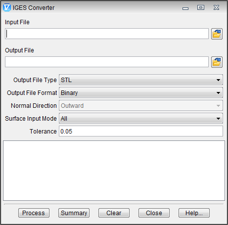
IGES Converter window
Tips:
-
When expecting to use IGES data for solid models in Vericut, ensure that surface normal vectors point Unidirectionally outwards in the CAD model prior to outputting the IGES data.
-
The Stock Consistency Check option is recommended for use with converted IGES models used to represent a stock workpiece.
Input File — The name of the file containing the IGES data to convert. Enter the /path/filename in the Input File text field or click on the  (Browse) icon to display the Select Input File file selection window and use it to specify the /path/filename.
Output File — The name of the file to receive converted geometry. Enter the /path/filename in the Output File text field or click on the (Browse) icon to display the Select Output File file selection window and use it to specify the /path/filename.
Output File Type — The type of output file to be created. Options are: Vericut or STL.
Output File Format — The format of the output file. Options are: BINARY or ASCII.
Normal Direction — The direction in which surface normal vectors point, as viewed in the CAD system. Feature only applicable to Vericut output file types. Options: OUTWARD or INWARD.
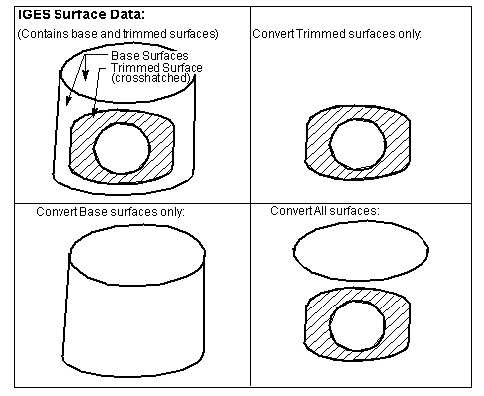
Surface Input Mode — Controls which IGES surfaces to convert. Options:
-
ALL — Convert all surfaces. With this mode, base surfaces associated with trimmed surfaces are only converted as trimmed surfaces; not in addition to trimmed surfaces.
-
BASE — Convert base surfaces only.
-
TRIMMED — Convert trimmed surfaces only.
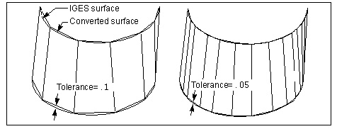
Tolerance — Use to specify the amount of chordal deviation allowed in 3-D space from the IGES surface when creating the converted surface. The converted surface is approximated using "facets", or triangles.
Process — Process (convert) the IGES data according to the current window settings. Converted geometry is written to the Output file. Error and informational messages from the process are sent to the IGES Converter window message area, and to a log file named "iges2v.log" created in the working directory.
Summary — Prints a summary of the Input file contents to the IGES Converter window message area.
Clear — Clears the IGES Converter window message area.
Close — Closes the IGES Converter window.
Help — Displays this Help page. (You can also use the F1 key to display this Help page.)
IGES data and version support
Vericut's IGES Converter converts the IGES data types listed below. The IGES Converter does not convert 2-D geometry data; however, this geometry is used to determine boundaries and trimming curves. Only 3-D surfaces, solids, and their supporting geometry are converted.
100: Circular arc
102: Composite curve
104: Conic arc (parabola, ellipse, hyperbola)
106: Copious data
108: Plane (bounded)
110: Line
112: Parametric spline curve
114: Parametric spline surface
116: Point
118: Ruled surface
120: Surface of revolution
122: Tabulated cylinder
124: Transformation Matrix
126: Rational B-spline curve
128: Rational B-spline surface
130: Offset curve
140: Offset surface
142: Curve on parametric surface
144: Trimmed parametric surface
150: Block
152: Right angular wedge
154: Right circular cylinder
156: Right circular cone frustum
158: Sphere
160: Torus
162: Solid of revolution
164: Solid of linear extrusion
168: Ellipsoid