Export CAD Model Settings
Location:
File tab > ![]() (Export CAD Model Settings)
(Export CAD Model Settings)
The Export CAD Model Settings command button opens the Export CAD Model window enabling you to specify various options related to exporting CAD models.
Apply — Saves the Export Model window settings.
Output — Processes and exports the Vericut model according to the Export Model window settings.
Close — Closes the Export Model window.
Settings tab
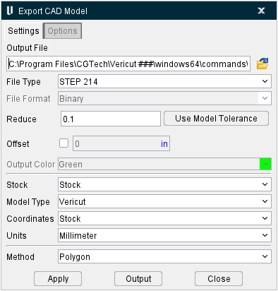
Output File — Use this feature to specify the file that is to receive exported model data. Enter the /path/filename in the Output File text field or click on the  (Browse) icon and use the Export Model File selection window to specify the /path/filename.
File Type — Use to specify the type of file to export. Options are: Vericut, STL, IGES, CATIA V5, ACIS, CATIA V4 and STEP.
File Format — Use to specify the format in which STL or Vericut model data is exported. Options are: ASCII or Binary.
Reduce — Toggle on (checked) to reduce file size. Feature is on by default. See the Open window for Models section for more information.
Use Model Tolerance — Use to populate the Reduce field with the model's preset tolerance.
Offset — Toggle on (checked) to offset file size. See the Open window for Models section for more information.
Output Color — Use to specify the color that is stored in the IGES file for the exported model. (Only active when File Type = IGES)
Stock — When multiple Stock components are defined, this option enables you to select which one to export.
Model Type — Use this dropdown menu to select the file type for the model. Options include: Vericut (default), AUTODIFF Gouge, AUTODIFF Excess, Die Sink, and Die Sink Burned Material. The File Format supported for AUTODIFF and Die Sink choices are STL, Vericut and all CAD formats. Only the “Polygon” method is supported when AUTODIFF or Die Sink is selected and the File Format is a CAD format.
Coordinates — Coordinate system in which model data is exported. Options are: Stock (stock component origin) or Active System (See Project tab > Active Coordinate System).
Units — Unit measurement system in which model data is exported. Options are: Inch or Millimeter.
Method — Controls the method of processing Vericut model geometry into the specified data format. Features and Patches, Features Only and Turned Features Only are only active when File Type = IGES, CATIA V5, ACIS, CATIA V4, or STEP. Slices is only active when File Type = IGES. Polygon is only active when File Type = CATIA V5, ACIS, CATIA V4, or STEP.
-
Features Only — Groups similar machined features into like IGES data entities. This option is recommended for cut models with distinct differences between machined features, for example: aerospace structural components, pocketed parts, parts with strengthening ribs/walls and stepped floors, etc.
-
Turned Features Only — Exports the turned, or "revolved", representation of the cut model. Turned models are exported as an IGES file and contain the 2-D turned profile and surface of revolution.
-
Slices — Exports the cut model such that resulting IGES output is a set of composite curves representing slice profiles of the cut stock.
-
Polygon — Saves a Polygon (faceted) representation of the cut stock model in one of the CAD model formats: STEP, CATIA 4, CATIA 5, ACIS.
Apply — Saves the Export Model window settings.
Output — Processes and exports the Vericut model according to the Export Model window settings.
Close — Closes the window without making any changes.
Options tab
The Options tab allows you to specify info related to the Slices method and, as a result, is only available when the Method feature is set to Slices.
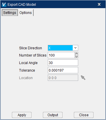
Slice Direction — Use this dropdown menu to select where the slices will happen along the X, Y, or Z axis.
Number of Slices — Use this field to set the number of slices.
Local Angle — Use this field to set the angle in degrees at which slices will be performed.
Tolerance — Use to set the value at which this process should ignore collisions.
Location — Use this field to specify the XYZ coordinates. You can also use the mouse icon to manually select the coordinates by clicking on the graphics window.
Tips on exporting models:
-
Make sure that Model Export Cut Mode in the Settings window: Properties tab (Project tab > Settings dropdown menu > Properties) is toggled "On" (checked).
-
Make sure that Display Holders in Workpiece View in the Project Tree > Configure Tooling menu > Holder Visibility feature is toggled "Off".
- Make sure that Visibility is set such that models of fixture components are not visible in the Workpiece View. See Model menu > Model Definition > Component Attributes tab for more information.
- When you cut the model a message similar to "For best AUTO-DIFF, Optimization and Model Results, set Cut Tolerance to 0.XXXX, due to small tool features" will appear in the logger. Use this information as a starting point for setting Cutting Resolution values Settings window: Properties tab (Project tab > Settings dropdown menu > Properties).
- To export a higher quality model, reduce the Cutting Resolution.
- You can section cut models, then export what remains in the sectioned view. This can be helpful to export portions of complex models on computers with limited resources.