CNC Machine Connectivity
Location:
Utilities tab >  (Machine Connectivity)
The Machine Connectivity command button opens the CNC Machine Connectivity window which enables Vericut users to connect to real CNC machines, further enhancing a Vericut simulation to achieve a more accurate Digital Twin of the real asset on the shop floor. CNC Machine Connectivity consists of several modules that help in double checking the machine setup prior to running the NC program on the real machine, connecting directly to the CNC machine to view how the machine is running, and replaying archived data in Vericut from when serialized parts were machined to investigate when a problem occurs.
CNC Machine Connectivity contains the following:
CNC Machine Connect — Consists of both Precheck options
-
Precheck — Compare critical data from the real CNC machine to that same data in a VMC within Vericut prior to running the NC program. Precheck can be ran to compare the parameters, initial machine location, work offsets, tool length offsets, and NC program(s) and subroutines from what was simulated in Vericut to what is setup on the CNC machine.
-
CNC Precheck — Allows Precheck capability down at the CNC machine to be performed by the Operator to verify key aspects of machine setup previously verified in Vericut. CNC Precheck will act as a “go/no go” gauge for the Operator to check just before pressing cycle start to start machining the part; there is no visual comparison of the data compared within CNC Precheck. This application provides convenient red and green lights to highlight if the 5 key items (parameters, initial machine location, work offsets, tooling offsets, NC program) match or if a difference is found. CNC Precheck is a standalone application that is included with Precheck and can be installed on as many shop floor Windows computers or Windows tablets as needed. Notifications can be sent automatically to the appropriate people via Microsoft Teams, text, and/or email of CNC Precheck comparison results.
-
CNC Machine Monitoring — Allows for a live connection to an active CNC machine to display its current status. Vericut will display the machine positioning per the NC program running on the physical CNC machine along with the active tool. Additional information pertaining to the status of the CNC machine can be displayed in the HUD (Heads Up Display) in the View as well as in the Status window.
-
Postcheck — Compare data archived from the real CNC machine to what was simulated in Vericut. Use to verify how the NC program ran on the real CNC machine and use to investigate out of spec parts.
Currently, this CNC Machine Connectivity works with the following controllers:
FANUC 0i, 30i, 31i, 32i, 35i

Makino Pro 5, Pro 6 (FANUC based)

DMG Mori w/ CELOS, w/ FANUC (FANUC based)

DMG Mori w/ FANUC 0i, 30i, 31i, 32i, 35i (pre CELOS) (FANUC based)

Okuma OSP-P300, OSP-P300A, OSP-P500
This connection works with the following machine monitoring solutions to connect, gather, and utilize information from the real CNC machine. You must have machine monitoring software in place for CNC Machine Connectivity to work.
| Machine Monitoring Company | Software | Website |
|---|---|---|
| Scytec | DataXchange | https://scytec.com/ |
Connection
Host — This is the address to connect to the machine monitoring software. Do not include the ‘http://’ in front of the address. An IP address alias (name) can also be entered if correctly defined correctly (connect.cgtech.com)
Port — This is the port number for the connection to the machine monitoring software.
Connect — Use to connect once the Host and port fields are populated. Once a connection has been made, "Connection was successfully established with (machine monitoring software name)." displays at the bottom of the window. If the connection was unsuccessful, "Unable to connect to (machine monitoring software name), please check the host address and port number." displays.
CNC Machines — Displays a list of available CNC machines being monitored via the machine monitoring software. Select the specific CNC machine name you want to connect to.
📝 NOTE: A successful connection is necessary for Precheck, CNC Machine Monitoring, and Postcheck to work.
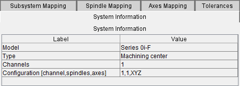
Configuration
System Information — Displays information from the machine monitoring software about the CNC machine and controller
-
Model — Displays the model of the controller on the CNC machine.
-
Type — Displays the type of CNC machine you are connected to.
-
Channels — Displays the number of available path or channels of the CNC Machine.
-
Configuration [channel, spindle, axes] — Displays the channel(s), spindle(s), and axes from the CNC machine you are connected to.
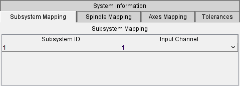
Subsystem Mapping — Displays the number of paths/channels available from the CNC machine controller. In some cases the naming of the Subsystem ID and Input Channel may not exactly match coming from the controller to what is labeled in Vericut. If the controller has just a single channel the Subsystem ID and Input Channel will be automatically aligned to 1:1. If the controller has multiple paths/channels the user must align the correct Input Channel to the correct Subsystem ID the first time the CNC Machine is selected to connect to. This mapping will then be stored in Vericut for that particular CNC Machine for future use.
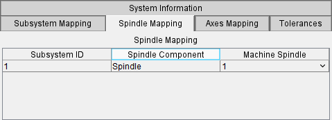
Spindle Mapping tab — Displays the mapping of the Vericut spindle relative to each subsystem to the CNC machine spindle(s). If the CNC machine has more than one spindle the Vericut spindle names will need to be mapped accordingly to align with the CNC machine spindles. If the CNC machine has just a single spindle the Machine Spindle is automatically mapped to 1. This mapping will then be stored in Vericut for that particular CNC Machine for future use.
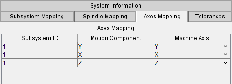
Axes Mapping — Displays the mapping of the Vericut axes relative to each axes to the CNC machine. If the CNC machine axes names match the axes names within Vericut the mapping will automatically align. Should an axes name be different select the appropriate corresponding name from the pulldown list. This mapping will then be stored in Vericut for that particular CNC Machine for future use.
📝 NOTE: In the event that an unnecessary Motion Component is listed from Vericut that is not needed for CNC Machine Connectivity (I.e. DoorTC, ARM, etc.), the Machine Axis field can be left blank. A message will appear in the CNC Machine Connectivity window “Not all axes were mapped. Some motions might not appear during Live Monitoring simulation.” When CNC Machine Monitoring is started but the positioning of Vericut relative to the Axes being streamed will still work.
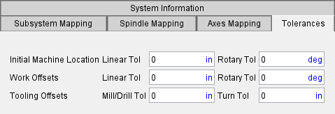
Tolerances tab — Displays tolerances that can be used for the Initial Machine Location, Work Offsets, and Tooling Offsets. These tolerances are not mandatory to use but will likely be needed to allow for variation from the “perfect” data in Vericut to the real setup and tooling on the CNC machine. All tolerances entered is ± value.
-
Initial Machine Location — Displays a linear and rotary tolerance that will be applied when comparing the Initial Machine Location in Vericut to the Initial Machine Location on the CNC machine.
-
Work Offsets — Displays a linear and rotary tolerance that will be applied when comparing the Work Offsets in Vericut to the Work Offsets on the CNC machine.
-
Tooling Offsets — Displays a tolerance for mills, drills, and turning tools that will be applied when comparing the tooling lengths (Gauge Point to Driven Point) in Vericut to the tool lengths on the CNC machine. There is a tolerance for mill and drill type tooling and a separate tolerance for turning tools.
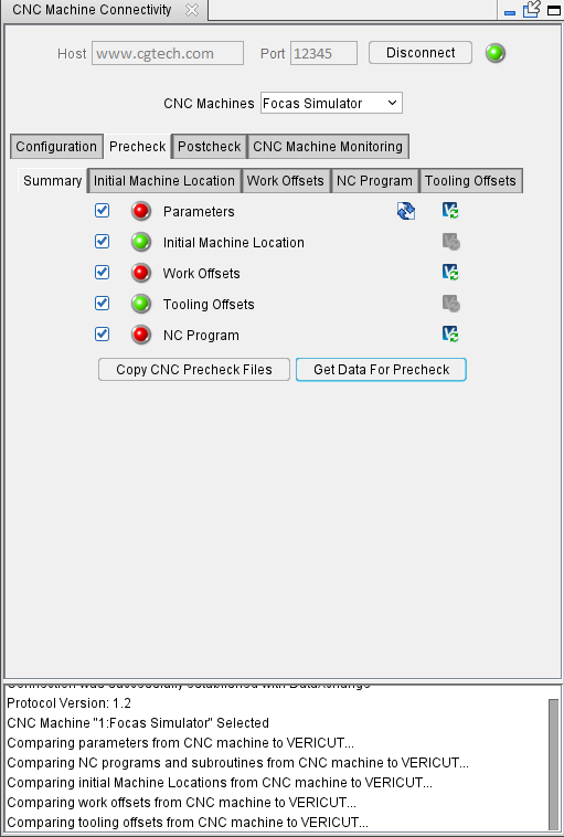
Precheck
Summary — The Summary tab provides a list of the available data points to verify in the Precheck process. The data points can be checked ON/OFF to compare the data on the real CNC machine vs. what is used in the Vericut simulation.
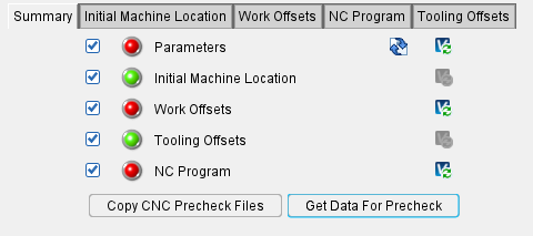
Copy CNC Precheck Files — Press this button to copy a separate version of the active Vericut files for use with CNC Precheck for the shop floor.
📝 NOTE: This set of Vericut files will be put in a separate folder using the .vcproject name. This folder location needs to be in a location where the shop can access the files for use in CNC Precheck.
Get Data for Precheck — Press this button to compare the data points from what was simulated in Vericut to what is currently setup on the CNC machine. CNC Precheck and this Precheck perform the same comparison of data but in this window will display differences in detail and allow for the update of Vericut data in the following tabs.
When the Precheck process is finished, the lights will display the following to indicate what was found during the comparison.
 Dark green — The data point was not checked or data for that item was not found.
 Light green — The data was successfully found in the real CNC machine and matches what is found in Vericut
 Red — The data was successfully found in the real CNC machine but does not match what is found in Vericut
If Precheck detects differences for any of the data points these value comparisons can be viewed on their respective tab.
Parameters — This option compares parameters set in Vericut’s Machine Settings Initialization File (Vericut > Machine/Control tab > Machine Settings > Initialization File) to the parameters set in the real CNC machine. It is important that these values match as they control how the machine behaves and moves.
📝 NOTE: It is strongly recommended that your VMC (Vericut Machine Control) start file for each CNC machine is updated with the latest controller information from Vericut.
-
 Compare Files… — This button becomes active if differences are found in the parameters from Vericut compared to the real CNC machine to display in a comparison program.
 -
 Update Vericut — If differences are found during the Precheck comparison process, the Update Vericut button becomes active to update Vericut with the latest parameters from the real CNC machine.
Initial Machine Location — This option compares the Initial Machine Location set in Vericut’s Offsets window (Vericut > Project tab > Offsets > Machine: Locations > Initial Machine Location) to the current location from the real CNC machine.
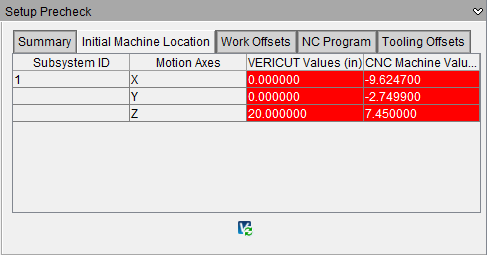
📝 NOTE: This comparison will only highlight differences outside the tolerance values set on the Tolerances tab.
- Update Vericut — If differences are found during the Precheck comparison process, the Update Vericut button updates Vericut’s Initial Machine Location with the current values from the real CNC machine.
Work Offsets — This option compares the Work Offsets set in VEIRCUT’s G-Code Offsets (Vericut > Project Tree > G-Code Offsets) to the current Work Offsets in the real CNC machine.
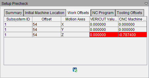
📝 NOTE: This option only compares work offsets set prior to running the NC program. Work Offsets that are created/set while the NC program is running will not be verified as they are not present until after the NC program is started.
📝 NOTE: This comparison will only highlight differences outside the tolerance values set on the Tolerances tab.
- Update Vericut — If differences are found during the Precheck comparison process, the Update Vericut button becomes active to update Vericut with the latest Work Offsets from the real CNC machine.
NC Program — This option compares the NC Program and any subroutine files present in Vericut’s NC Programs (Vericut > Project Tree > NC Programs) to the current NC Program and subroutines in the real CNC machine.
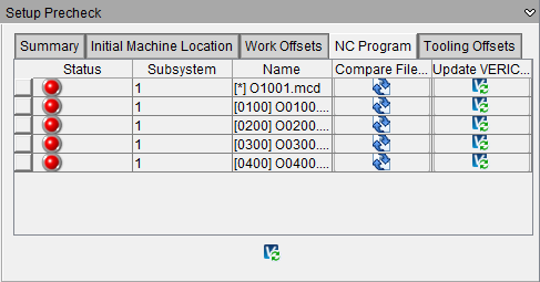
Compare Files… — If differences are found in any of the subroutines this button becomes active to view the files from Vericut and the real CNC machine in a comparison program.
Update Vericut — If differences are found in the NC Program, the Update Vericut button becomes active to update Vericut with the latest NC Program file from the real CNC machine.
Tooling Offsets — This option compares tooling ID’s and tool lengths present in Vericut’s Tool Manager (Vericut > Project Tree > Tooling) that are used in the specific NC Program you're ready to run on the real CNC machine.
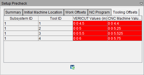
📝 NOTE: This option works with some controllers. In some instances of Fanuc controllers there is no current method to align tool ID’s and their respective tool lengths (Vericut’s Driven Point value).
📝 NOTE: This option works whether tooling in Tool Manager is built from tip to holder or holder to tip. The Update Vericut functionality will update the assembly positions of the appropriate components.
📝 NOTE: This comparison will only highlight differences outside the tolerance values set on the Tolerances tab.
- Update Vericut — If differences are found in any tool used the Update Vericut button becomes active to Update Vericut with the tool offset length from the real CNC machine.
Rerun the Vericut simulation with data from the real CNC machine — Vericut simulation can be rerun with any updated values to reverify the simulation using data currently set on the CNC machine. Precheck is intended to compare and highlight differences from the way the Vericut simulation is setup to what is actually setup on the real CNC machine. Some users may want to use the updated values from the real CNC machine while others may want to update the real CNC machine with data from Vericut.
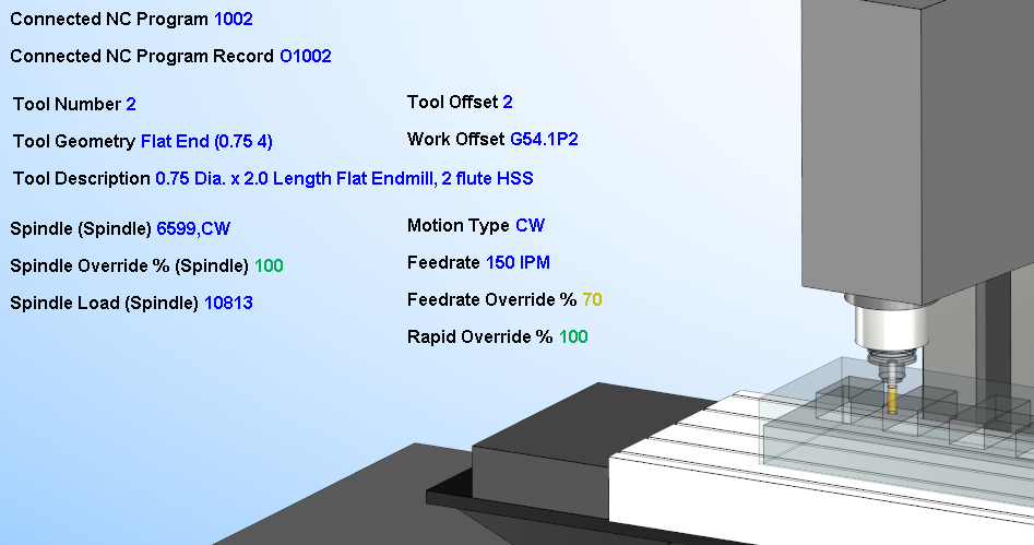
CNC Machine Monitoring
Start CNC Machine Monitoring — Press this button to connect to the physical CNC machine to start positioning Vericut and displaying status information. Vericut will display the machine positioning per the NC program running on the physical CNC machine along with the active tool. Press Stop CNC Machine Monitoring to end the connection. Most other Vericut functionality will be disabled while connected except for being able to zoom and rotate the View.
Additional information pertaining to the status of the CNC machine can be displayed via the following in Vericut:
-
Status window (See Connectivity Group)
Speed (Milliseconds) — Speed value, in milliseconds, to be used to control how fast to poll the server to retrieve data from the CNC machine. Default value is 250.
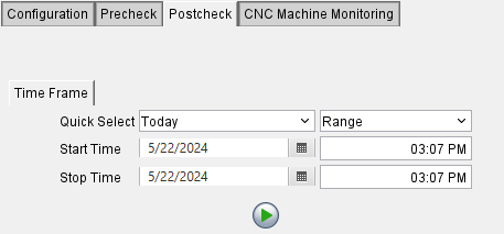
Postcheck
Time Frame — Find specific date and time range to replay archived data from when a specific part was ran on a CNC machine.
-
Quick Select — Select from the Today and Range pulldown lists to preselect a date and time frame. These selections will automatically adjust the Start and Stop Time date and time fields.
-
Start Time — Allows for entry of a specific start date in the date field or select from a calendar, if necessary. The time field allows for a specific start time to be entered, if necessary.
-
Stop Time — Allows for entry of a specific stop date in the date field or select from a calendar, if necessary. The time field allows for a specific stop time to be entered, if necessary.
![]() Play/Start Button — Click the Play Button to start the retrieval of archived data to be replayed in Vericut. The data being retrieved to replay will only be within the start and stop dates and times.
Play/Start Button — Click the Play Button to start the retrieval of archived data to be replayed in Vericut. The data being retrieved to replay will only be within the start and stop dates and times.