Tool Component tab
Accessed from the Tool Definition window, the features on this tab are used to define the shape of a tool component in a tool assembly. Features displayed on the Tool Component tab vary, depending on the tool/tool component type that you selected to add/modify.
See Adding a Tool to a Tool Library section of Vericut Help for additional information about creating tool components.
Tool Component tab (Common Features)
The following features are common to most of the Tool Component tab tool types.
Reference Features — The Reference Features enable you to "reference" a tool component in another tool library file for use in the current tool library file.
Model File Features — The Model File Features enable you to use an existing model or create a new Sweep Solid or Solid of Revolution using the Profile Sketcher to define a tool component.
Tool Display Colors — The Tool Display Colors feature enable you to specify the display color for tool components (cutters, inserts, and holders) in Tool Manager
Reference Features
The Reference Features enable you to "reference" a tool component in another tool library file for use in the current tool library file. The Reference icon appearance changes depending on which tool's Tool Component tab it is accessed from.
![]() for Revolved Cutters, Hole-Making Tools, Waterjet tools, Ultrasonic Knife tools, Polisher tools, Grinder tools, Dresser tools, and Holders.
for Revolved Cutters, Hole-Making Tools, Waterjet tools, Ultrasonic Knife tools, Polisher tools, Grinder tools, Dresser tools, and Holders.
![]() for Mill Inserts and Turning Inserts.
for Mill Inserts and Turning Inserts.
 for Probe Tips.
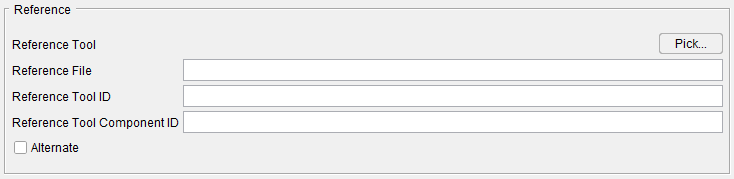
Common Reference features
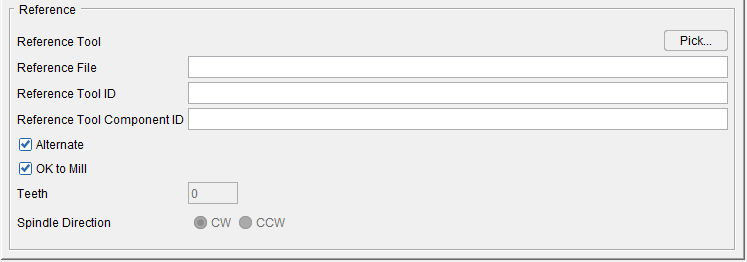
Standard Hole Making Tool Reference features
Reference features:
Pick — Pressing the Pick button displays the Search Tool window enabling you to search existing tool libraries for tools with specific attributes that you want to "reference". See Search Tool window section of Vericut Help for additional information.
Reference File — Enter the /path/filename of the tool library file containing the tool component to be referenced in the text field or use the Pick button to display the Search Tool window and use it to select the tool library file.
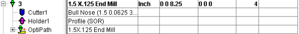
Reference Tool ID — Enter tool ID of the tool component to be referenced in the text field or use the Pick button to display the Tool Search window and use it to select the tool component to be referenced. In the sample tool record in the picture below, the Reference Tool ID is 6
Reference Tool Component ID — Enter tool component ID of the tool component to be referenced in the text field or use the Pick button to display the Tool Search window and use it to select the tool component to be referenced. In the sample tool record in the picture below, the Reference Tool Component ID is Cutter1
Alternate — When toggled "on" (checked) this feature designates the cutter that is being created as an "alternate" or "secondary" cutter for a particular tool assembly. This feature enables you to switch between a "primary" and "alternate" cutter shape, in order to support tools such as back-boring tools.
The AlternateTool macro is used to specify whether to use the "primary" (Override Value = 0) cutter shape or to use the "alternate" (Override Value = 1) cutter shape. See Create and Use Tools with Alternate Cutters in the Using the Tool Manager section of Vericut Help for additional information and examples.
OK to Mill — When toggled “on” (checked), the OK to Mill feature overrides the default check for axial cuts only enabling you to machine with Hole Making Tools, Turn Inserts and Polisher Tools other than along the tool axis.
Teeth — Displays the number of teeth.
Spindle Direction — Toggle between the clockwise options (CW) and the counterclockwise option (CCW).
Model File Features
The Model File features enable you to use an existing model or create a new Sweep Solid or Solid of Revolution using the Profile Sketcher to define a tool component. The features that display will vary depending on the type of tool component. Each of the variations is illustrated in the pictures below.
The Model File feature is accessed using the ![]() (Model File) icon on the Tool Component tab for Mill Inserts, Turn Inserts, Hole Making Tools and Insert models created using the Import CAD Tool window.
(Model File) icon on the Tool Component tab for Mill Inserts, Turn Inserts, Hole Making Tools and Insert models created using the Import CAD Tool window.
Hole Making Tools
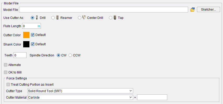
Model File — Enter the /path/filename of the model file or click on the  (Browse) icon to display the Open file selection window and use it to specify the /path/filename of the model file.
Sketcher — Displays the Profile Sketcher window enabling you to edit or create a "swept solid (.swp)" or "solid of revolution (.sor)" model file. This feature is only available the selected file is a SOR or SWEEP file type. To create a new SOR or SWEEP model file, clear the Model File text field and press Sketcher.
Use Cutter As — Use to toggle between Drill, Reamer, Center Drill, and Tap options.
Maximum Material Removal Per Side — Use to specify the maximum amount of material that can be removed by the reamer. This option is only available when Use Cutter As is set to Reamer.
Thread Depth — Use to specify the thread depth. This option is only available when Use Cutter As is set to Tap.
Thread — Use to specify threads per preferred measurement. This option is only available when Use Cutter As is set to Tap.
or Pitch — Use to set the measurements independent of the threads. Only this option or Thread can be set but both cannot be active. This option is only available when Use Cutter As is set to Tap.
Direction — Use to set the rotational direction to the Right or to the Left. This option is only available when Use Cutter As is set to Tap.
Lead Tolerance — Use to set a percentage tolerance. Maximum allowable percentage is 100 and minimum allowable is 0. This option is only available when Use Cutter As is set to Tap.
Forms — Use to specify desired measurement. Current options include Unified (Inch), ISO (metric), Whitworth (British standard), Acme, and Buttress. This option is only available when Use Cutter As is set to Tap.
Flute Length — Use to specify the length of the tool. If Use Cutter As is set to Tap, Flute Length value is counted as a Thread Length value instead.
Color — The Color icon, enables you to specify a color for that particular tool (options currently include Cutter and Shank). The color of the Color icon shows the current color of the tool. To change the color, click on the  (Color Palette) icon to display the color palette window shown below.
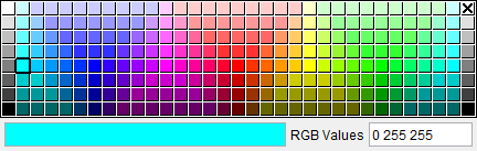
Click on a color in the color palette window, to specify the color for the tool. The color palette window will close and the right side of the  (Color Palette) icon in the Color window will update to reflect the selected color.
To close the color palette window without changing the color, click on the ![]() in the upper right corner of the color palette window.
in the upper right corner of the color palette window.
Teeth — Number of Teeth defined for Hole Making Tool.
Spindle Direction — Use to specify the appropriate spindle rotation direction for the tool. Choose either CW (clockwise) or CCW (counterclockwise).
📝 NOTE: For revolved milling cutters, CW/CCW is defined looking down (negative Z) the tool axis.
Alternate — When toggled "on" (checked) this feature designates the cutter that is being created as an "alternate" or "secondary" cutter for a particular tool assembly. This feature enables you to switch between a "primary" and "alternate" cutter shape, in order to support tools such as back-boring tools.
The AlternateTool macro is used to specify whether to use the "primary" (Override Value = 0) cutter shape or to use the "alternate" (Override Value = 1) cutter shape.
See Create and Use Tools with Alternate Cutters in the Using the Tool Manager section of Vericut Help for additional information and examples.
Cutter Material — Use to specify the material that the cutter is made of. Select the material type from the pull-down list.
Tool Display Colors
The display color for tool components (cutters, inserts, and holders) in Tool Manager and all Vericut views is determined by the conditions described below:
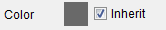
- Tool components (Cutter or Holder) with Color set to a specific color (Inherit toggled “off”) on the Tool Definition window: Tool Component tab are displayed in the specified color both in Tool Manager and in all views in the Vericut graphics area when the component(s) are loaded in the “active” Spindle.
Color — Use the  (Color Palette) feature to specify a color for the tool component.
The right side of the (Color Palette) icon shows the current color for the component. To change the color for the tool component, click on the (Color Palette) icon to display the color palette window shown below.

Click on a color in the color palette window, to specify the color for the tool component. The color palette will close and the right side of the  (Color Palette) icon in the Tool Definition window: Tool Component tab will update to reflect the selected color.
To close the color palette window without changing the color, click on the  in the upper right corner of the color palette.
The cuts made by cutter or insert components are also shaded with this color when Color Method, on the Color window: Cut Colors tab, is set to "Tool Color".
Available colors are defined in the Shade Colors list on the Color window: Define tab.
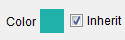
- Tool Holders with Color set to Inherit on the Tool Definition window: Tool Component tab will always be displayed with color number 5 from the Shade Color list on the Color window: Define tab. This applies both to holders displayed in Tool Manager and holders displayed in the Vericut graphics area when the tool is loaded in the “active” Spindle.
- Cutters or Inserts with Color set to Inherit on the Tool Definition window: Tool Component tab will be displayed with the "current" cut color, from the Cut Color Table on the Color window: Cut Colors tab, in the Vericut graphics area when the tool is loaded in the “active” Spindle.
See Color window in the Configuration tab section of Vericut Help for additional information.
Turrets and Tool Chains
The display color for tool components in turrets and tool chains are displayed is determined by the conditions described below:
- Tool components (Cutter or Holder) with Color set to a specific color on the Tool Definition window: Tool Component tab are displayed in the specified color. This applies both to tool components displayed in Tool Manager and tool components displayed in the Vericut graphics area when on a turret or tool chain.
Color — Use the (Color Palette) feature to specify a color for the tool component.
The right side of the (Color Palette) icon shows the current color for the component. To change the color for the tool component, click on the (Color Palette) icon to display the color palette window shown below.
Click on a color in the color palette window, to specify the color for the tool component. The color palette will close and the right side of the (Color Palette) icon in the Tool Definition window: Tool Component tab will update to reflect the selected color.
To close the color palette window without changing the color, click on the in the upper right corner of the color palette.
- Tool Holders with Color set to Inherit on the Tool Definition window: Tool Component tab will always be displayed with color number 5 from the Shade Color list on the Color window: Define tab. This applies both to holders displayed in Tool Manager and holders displayed in the Vericut graphics area when the tool is on a turret or tool chain.
- Cutters or Inserts with Color set to Inherit on the Tool Definition window: Tool Component tab will be displayed with color number 7 from the Shade Color list on the Color window: Define tab when initially loaded into a turret or tool chain or in Tool Manager.
- Cutters or Inserts with Color set to Inherit on the Tool Definition window: Tool Component tab will be displayed with the "current" cut color, from the Cut Color Table on the Color window: Cut Colors tab, when the tool is used to cut. Vericut does not know the tool's sequence until it is used to cut. The tools will then be displayed in this color when on a turret or tool chain.
See Color window in the Configuration tab section of Vericut Help for additional information.
Tool Component tab (Hole Making Tool)
Opened via adding or modifying a Hole -Making tool, this tab is used to describe the shape for the "Cutter" component in a Hole-making tool assembly. Options are available to define the cutter via parametric shapes, profile sketcher, or reference a cutter in another tool assembly.
Tool shape icons — Selecting an icon configures the bottom half of the window to define the selected cutter shape.
 (Drill) — Opens the Drill feature definition panel enabling you to specify the cutter’s characteristics.
 (Reamer) — Opens the Reamer feature definition panel enabling you to specify the cutter’s characteristics.
 (Center Drill) — Opens the Center Drill feature definition panel enabling you to specify feature definition panel enabling you to specify the cutter’s characteristics.
 (Tap) — Opens the Tap Tool feature definition panel enabling you to specify the cutter’s characteristics.
 (Revolve Profile) — Opens the Profile Sketcher window in “solid of revolution” mode enabling you to create Revolved Cutter components by rotating a defined profile around the Z- axis.
See Profile Sketcher window in the Configure Model tab section of Vericut Help.
![]() (General Insert) — Displays the General Insert features panel enabling you to define ISO standard insert shapes.
(General Insert) — Displays the General Insert features panel enabling you to define ISO standard insert shapes.
![]() (Reference) — Displays the Reference Features enabling you to "reference" a tool component in another tool library file for use in the current tool library file.
(Reference) — Displays the Reference Features enabling you to "reference" a tool component in another tool library file for use in the current tool library file.
![]() (Model File) — The Model File Features enable you to use an existing model or create a new Sweep Solid or Solid of Revolution using the Profile Sketcher to define a tool component.
(Model File) — The Model File Features enable you to use an existing model or create a new Sweep Solid or Solid of Revolution using the Profile Sketcher to define a tool component.
See Define a Hole Making Cutter section of Vericut Help for information on creating inserted milling tools.
See Assembly tab section for information on positioning, and orienting, a mill insert component in a milling tool assembly.
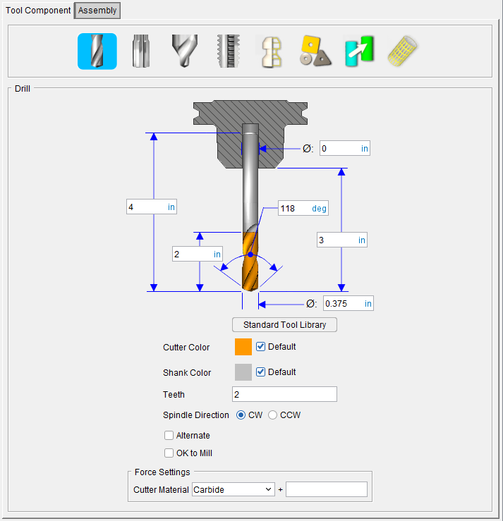
Hole Making Tool, Drill
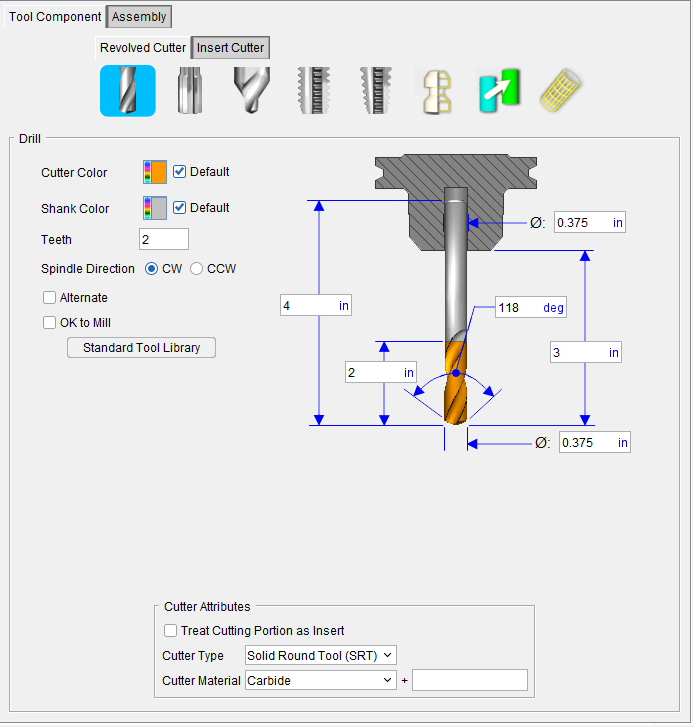
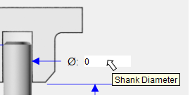
Tip: Hold the cursor over a number field in the tool diagram to see a tip indicating what value the field represents.
📝 NOTE: The acronyms in this section align to the ISO parameters in the ISO 13399 standard.
Height (OAL) — Use to specify the height of the tool.
Flute Length (LU) — Use to specify the length of the portion of the cutter having flutes, or teeth that can remove material. This value is measured from the bottom-most portion of the cutter. Zero assumes the entire cutter length has flutes, or teeth that can cut material. An error similar to "SHANK removed material..." is reported when the non-cutting portion of the cutter removes material. Material removed is shaded using the red Error color.
Shank Diameter (DCON) — Use to specify the diameter of the tool shank.
Drill Point Angle (SIG) — Use to specify the angle of the drill point.
Stick-out Length (LGTA) — Use to specify the length of the tool that sticks out from the holder. This value is measured from the bottom-most portion of the cutter to the bottom-most portion of the holder.
Cutting Diameter (DC) — Use to specify the diameter of the tool.
Standard Tool Library — Displays the Standard Tool window enabling you to select a drill from a Standard Tool Library of drills. Selecting a drill from the Standard Tool Library will automatically enter all of the parameters required to define the drill.
Color — Color that the tool component is to be displayed in Vericut. For additional information, see Tool Display Colors in the Tool Component tab, Common Features section.
Teeth — The number of teeth for the tool is automatically entered based on the Teeth value in the “active” optimization record associated with the tool/tool assembly.
📝 NOTE: You have the ability to manually edit the number of teeth by typing in a value but be aware that if the number of teeth entered does not match the number of teeth specified in the optimization record, the tool will not be optimized.
Spindle Direction — Use to specify the appropriate spindle rotation direction for the tool. Choose either CW (clockwise) or CCW (counterclockwise).
📝 NOTE: For drills, CW/CCW is defined looking down (negative Z) the tool axis.
Alternate — When toggled "on" (checked) this feature designates the cutter that is being created as an "alternate" or "secondary" cutter for a particular tool assembly. This feature enables you to switch between a "primary" and "alternate" cutter shape, in order to support tools such as back-boring tools.
The AlternateTool macro is used to specify whether to use the "primary" (Override Value = 0) cutter shape or to use the "alternate" (Override Value = 1) cutter shape.
See Create and Use Tools with Alternate Cutters in the Using the Tool Manager section of Vericut Help for additional information and examples.
OK to Mill — When toggled “on” (checked), the OK to Mill feature overrides the default check for axial cuts only (hole making) enabling you to machine with a drill other than along the tool axis, for example using a drill tool to chamfer.
See Define a Hole Making Cutter section of Vericut Help for information on creating inserted milling tools.
See Assembly tab section for information on positioning, and orienting, a mill insert component in a milling tool assembly.
Hole Making Tool, Reamer
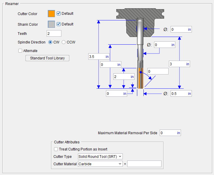
💡 Tip: Hold the cursor over a number field in the tool diagram to see a tip indicating what value the field represents.

📝 NOTE: The acronyms in this section align to the ISO parameters in the ISO 13399 standard.
Height (OAL) — Use to specify the height of the tool.
Neck Length (LB) — Use to specify the length of the tool neck.
Flute Length (LU) — Use to specify the length of the portion of the cutter having flutes, or teeth that can remove material. This value is measured from the bottom-most portion of the cutter. Zero assumes the entire cutter length has flutes, or teeth that can cut material. An error similar to "SHANK removed material..." is reported when the non-cutting portion of the cutter removes material. Material removed is shaded using the red Error color.
Chamfer Height (PLGL) — Use to specify the height of the chamfer at the end of the tool.
Shank Diameter (DCON) — Use to specify the diameter of the tool shank.
Neck Diameter (ND) — Use to specficy the diameter of the tool neck.
Stick-out Length (LGTA) — Use to specify the length of the tool that sticks out from the holder. This value is measured from the bottom-most portion of the cutter to the bottom-most portion of the holder.
Plug Angle (PLGANG) — Use to specify the angle of the chamfer at the end of the tool. Default value is 45. If the Chamfer Height value is 0, Plug Angle will not display the chamfer in the geometry.
Cutting Diameter (DC) — Use to specify the diameter of the tool.
Standard Tool Library — Displays the Standard Tool window enabling you to select a reamer from a Standard Tool Library of reamers. Selecting a reamer from the Standard Tool Library will automatically enter all of the parameters required to define the reamer.
Maximum Material Removal — Use to specify the maximum amount of material that can be removed by the reamer. If this field is set to 0, no material will be removed.
Color — Color that the tool component is to be displayed in Vericut. For additional information, see Tool Display Colors in the Tool Component tab, Common Features section.
Spindle Direction — Use to specify the appropriate spindle rotation direction for the tool. Choose either CW (clockwise) or CCW (counterclockwise).
📝 NOTE: For reamers, CW/CCW is defined looking down (negative Z) the tool axis.
Alternate — When toggled "on" (checked) this feature designates the cutter that is being created as an "alternate" or "secondary" cutter for a particular tool assembly. This feature enables you to switch between a "primary" and "alternate" cutter shape, in order to support tools such as back-boring tools.
The AlternateTool macro is used to specify whether to use the "primary" (Override Value = 0) cutter shape or to use the "alternate" (Override Value = 1) cutter shape.
See Create and Use Tools with Alternate Cutters in the Using the Tool Manager section of Vericut Help for additional information and examples.
OK to Mill — When toggled “on” (checked), the OK to Mill feature overrides the default check for axial cuts enabling you to machine with a Hole Making Tool other than along the tool axis.
See Define a Hole Making Cutter section of Vericut Help for information on creating inserted milling tools.
See Assembly tab section for information on positioning, and orienting, a mill insert component in a milling tool assembly.
Hole Making Tool, Center Drill
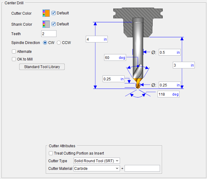
💡 Tip: Hold the cursor over a number field in the tool diagram to see a tip indicating what value the field represents.

📝 NOTE: The acronyms in this section align to the ISO parameters in the ISO 13399 standard.
Height (OAL) — Use to specify the height of the tool.
Chamfer Angle (STA) — Use to specify the angle of the countersink portion of the tool.
Pilot Length (SDL) — Use to specify the length of the pilot drill.
Shank Diameter (DCON) — Use to specify the diameter of the tool shank.
Stick-out Length (LGTA) — Use to specify the length of the tool that sticks out from the holder. This value is measured from the bottom-most portion of the cutter to the bottom-most portion of the holder.
Cutting Diameter (DC) — Use to specify the diameter of the tool.
Pilot Angle (SIG) — Use to specify the angle at the end of the pilot drill.
Standard Tool Library — Displays the Standard Tool window enabling you to select a center drill from a Standard Tool Library of center drills. Selecting a center drill from the Standard Tool Library will automatically enter all of the parameters required to define the center drill.
Color — Color that the tool component is to be displayed in Vericut. For additional information, see Tool Display Colors in the Tool Component tab, Common Features section.
Teeth — The number of teeth for the tool is automatically entered based on the Teeth value in the “active” optimization record associated with the tool/tool assembly.
📝 NOTE: You have the ability to manually edit the number of teeth by typing in a value but be aware that if the number of teeth entered does not match the number of teeth specified in the optimization record, the tool will not be optimized.
Spindle Direction — Use to specify the appropriate spindle rotation direction for the tool. Choose either CW (clockwise) or CCW (counterclockwise).
📝 NOTE: For center drills CW/CCW is defined looking down (negative Z) the tool axis.
Alternate — When toggled "on" (checked) this feature designates the cutter that is being created as an "alternate" or "secondary" cutter for a particular tool assembly. This feature enables you to switch between a "primary" and "alternate" cutter shape, in order to support tools such as back-boring tools.
The AlternateTool macro is used to specify whether to use the "primary" (Override Value = 0) cutter shape or to use the "alternate" (Override Value = 1) cutter shape.
See Create and Use Tools with Alternate Cutters in the Using the Tool Manager section of Vericut Help for additional information and examples.
OK to Mill — When toggled “on” (checked), the OK to Mill feature overrides the default check for axial cuts only (hole making) enabling you to machine with a drill other than along the tool axis, for example using a drill tool to chamfer.
See Define a Hole Making Cutter section of Vericut Help for information on creating inserted milling tools.
See Assembly tab section for information on positioning, and orienting, a mill insert component in a milling tool assembly.
Hole Making Tool, Tap
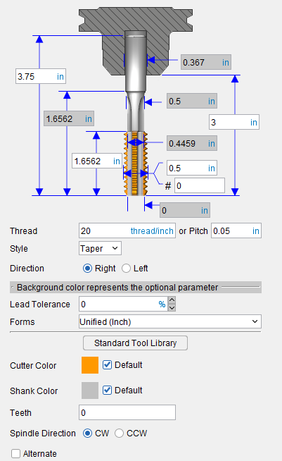
💡 Tip: Hold the cursor over a number field in the tool diagram to see a tip indicating what value the field represents.

Overall Length (OAL) — Use to specify the overall length of the tool.
Usable Length (LU) — Use to specify the distance between the shank and the threaded portion of the tap.
Thread Length (THL) — Use to specify the length of the threaded portion of the tool.
Shank Diameter (DCON) — Use to specify the diameter of the tool shank.
Neck Diameter (DN) — Use to specify the diameter of the tool’s neck area.
Minor Diameter — Use to specify the minor diameter of the thread
Major Diameter (TD) — Use to specify the major diameter of the thread.
Screw Thread Size — Use to specify the major diameter using the “Numeric Size” of the thread, for example #6.
Stick-out Length (LGTA) — Use to specify the length of the tool that sticks out from the holder. This value is measured from the bottom-most portion of the cutter to the bottom-most portion of the holder.
Tip Diameter (TCPD) — Use to specify the diameter if the tool at the tip of the threaded portion of the tool.
Thread — Use to specify the distance between adjacent threads. Enter either the number of threads per threads/inch or by the thread’s Pitch (distance between adjacent threads in mm).
Pitch (TP) — Use to specify the pitch.
Style — Use to specify the style of tap. Choose Taper, Plug or Bottom from the pull-down list.
Direction — Use to specify the direction (hand) of the thread. Choose Right or Left.
Optional Parameters — The following parameters are optional when defining a tap tool:
-
Lead Tolerance — Use to specify the lead tolerance as a percent. The lead tolerance is the amount of advancement for one revolution. For a single start thread the "Lead" equals the "pitch". For a double start thread the "Lead" is twice the "pitch". The tolerance is necessary in some cases because of computer round off and the number of decimal places available which in some cases may not always being "exact".
For example, a ¼"-28 thread:
1/28 = 0.035714, thus what do you program: 0.0357 or 0.0358, diff of 0.0001, for a percent of: 0.0001 / 0.0357 = 0.0028 or 0.28%, or 1% for the Lead Tolerance. -
Forms — Use to specify the thread form. Select the thread form from the pull-down list. Choose one of the following: Unified (Inch), ISO (Metric), Whitworth (British standard), Acme or Buttress.
Standard Tool Library — Displays the Standard Tool window enabling you to select a tap from a Standard Tool Library of tap tools. Selecting a tap from the Standard Tool Library will automatically enter all of the parameters required to define the tap.
Color — Color that the tool component is to be displayed in Vericut. For additional information, see Tool Display Colors in the Tool Component tab, Common Features section.
Teeth — The number of teeth for the tool is automatically entered based on the Teeth value in the “active” optimization record associated with the tool/tool assembly.
📝 NOTE: You have the ability to manually edit the number of teeth by typing in a value but be aware that if the number of teeth entered does not match the number of teeth specified in the optimization record, the tool will not be optimized.
Alternate — When toggled "on" (checked) this feature designates the cutter that is being created as an "alternate" or "secondary" cutter for a particular tool assembly. This feature enables you to switch between a "primary" and "alternate" cutter shape, in order to support tools such as back-boring tools.
The AlternateTool macro is used to specify whether to use the "primary" (Override Value = 0) cutter shape or to use the "alternate" (Override Value = 1) cutter shape.
See Create and Use Tools with Alternate Cutters in the Using the Tool Manager section of Vericut Help for additional information and examples.
See Define a Hole Making Cutter section of Vericut Help for information on creating inserted milling tools.
See Assembly tab section for information on positioning, and orienting, a mill insert component in a milling tool assembly.
Standard Tool window
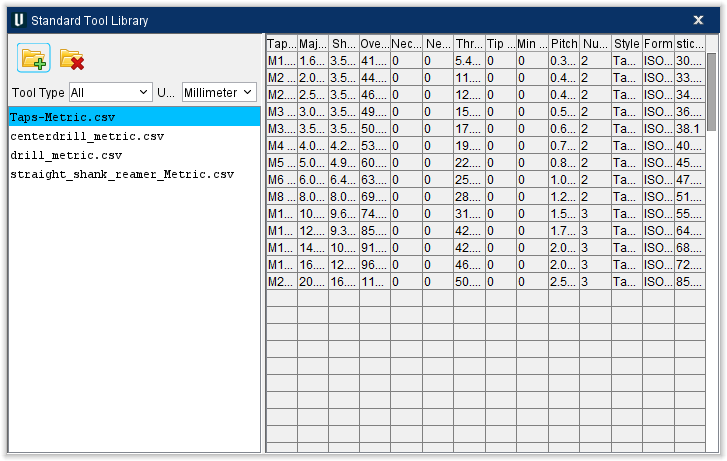
The Standard Tool Library feature, in the Standard Hole Making tool definition windows, displays the Standard Tool window enabling you to display a Standard Tool Library file containing a list of "standard" tools.
Selecting a tool from the Standard Tool Library will automatically enter all of the parameters required to define the tool in the Hole Making Tool definition window.
The following Standard Tool libraries are included in the Library folder of your Vericut installation.
centerdrill_inch.csv
centerdrill_metric.csv
drill_inch.csv
drill_metric.csv
straight_shank_reamer_inch.csv
straight_shank_reamer_Metric.csv
Taps-Inch.csv
Taps-Metric.csv
You can also create your own Standard Tool library. Standard Tool list is populated from information provided in CSV (Comma Separated Values) formatted files.
A tool record, populated with the necessary fields, must be included for each "standard" tool that is to appear in the tool list. Use the included Tool Library files as a guide.
![]() (Add Tool Library File) — Use to display the Open file selection window enabling you to select the Standard Tool Library file to be added to the Standard Tool window.
(Add Tool Library File) — Use to display the Open file selection window enabling you to select the Standard Tool Library file to be added to the Standard Tool window.
 (Remove Tool Library File) — Use to remove the highlighted Standard Tool Library file from the Standard Tool window.
Tool Type — Use to specify the type of Standard Tool. Select one of the following (Drill, Reamer, Center Drill, Tap) from the pull-down list.
Unit — Use to specify the units for the tool. Select Inch or Millimeter from the pull-down list.
Hole Making Tool, General Insert Features
Accessed using the ![]() (General Insert) icon on the Hole Making Tools Tool Component tab, the General Insert features enable you to define "ISO standard", as well as "custom" tool insert shapes.
(General Insert) icon on the Hole Making Tools Tool Component tab, the General Insert features enable you to define "ISO standard", as well as "custom" tool insert shapes.
General Insert Features for Hole Making Tools
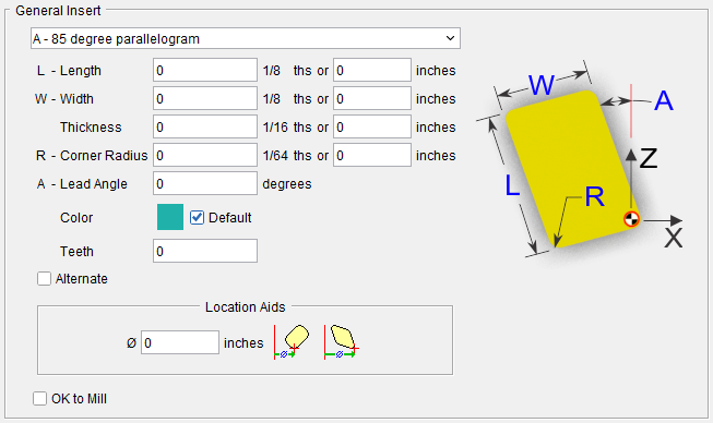
The parameters and diagram will vary depending on the Insert Type selected from the list. Only the parameters required to describe a particular insert type will be displayed. Select the desired insert type from the pull-down list. Below are common letters used in defining a parallelogram's shape listed alphabetically and what value the letter corresponds to:
-
A - Angle (sometimes Lead Angle)
-
D - Diameter
-
L - Length
-
R - Radius (sometimes Corner Radius)
-
T - Tip Angle
-
W - Width Thickness
📝 NOTE: Vericut uses a pre-defined "Relief Angle" of 5 degrees for all tool inserts created with Tool Manager.
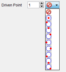
Driven Point — Use to specify the driven point for the insert. You can specify multiple driven points. Use the number box to specify which driven point that you are defining. In the picture below, driven point 2 is being defined. Select the desired driven point location for each driven point from the pull-down list. This feature is only available for Turn inserts.
Color — Color that the tool component is to be displayed in Vericut. For additional information, see Tool Display Colors in the Tool Component tab, Common Features section.
Alternate — When toggled "on" (checked) this feature designates the cutter that is being created as an "alternate" or "secondary" cutter for a particular tool assembly. This feature enables you to switch between a "primary" and "alternate" cutter shape, in order to support tools such as back-boring tools.
The AlternateTool macro is used to specify whether to use the "primary" (Override Value = 0) cutter shape or to use the "alternate" (Override Value = 1) cutter shape. See Create and Use Tools with Alternate Cutters in the Using the Tool Manager section of Vericut Help for additional information and examples.
OK to Mill — When toggled “on” (checked), the OK to Mill feature overrides the default check for axial cuts only enabling you to machine with a Hole Making Tool other than along the tool axis.
Tool Component tab (Knife)
Opened via adding, or modifying, a Knife tool component, this tab is used to describe the shape of an ultrasonic knife tool component in an ultrasonic knife tool assembly.
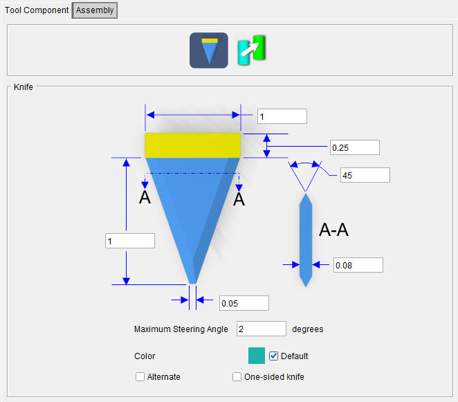
Tool shape icons — Selecting an icon configures the bottom half of the window to define the selected cutter shape.
Options:
![]() (Knife) — Opens the Knife feature definition panel enabling you to specify the ultrasonic knife’s characteristics.
(Knife) — Opens the Knife feature definition panel enabling you to specify the ultrasonic knife’s characteristics.
![]() (Reference) — Displays the Reference Features enabling you to "reference" a tool component in another tool library file for use in the current tool library file.
(Reference) — Displays the Reference Features enabling you to "reference" a tool component in another tool library file for use in the current tool library file.
See Define a Knife Cutter section of Vericut Help for information on creating Knife Cutters.
See Assembly tab section for information on positioning, and orienting, a knife tool component in a Knife tool assembly.
Knife
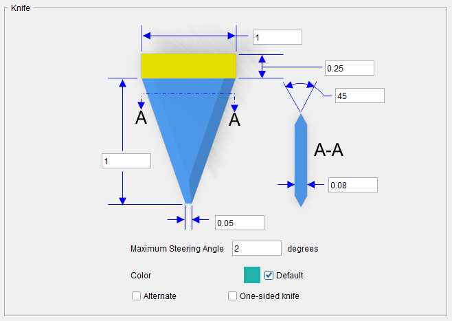
💡 Tip: Hold the cursor over a number field in the tool diagram to see a tip indicating what value the field represents.
Length (L) — Length of the knife blade. This measurement does not include the shank.
Width (W) — Total width of the knife tool.
Tip Width (D) — Width if the knife tool at its tip.
Shank Height (H) — Height of the shank portion of the knife tool.
lade Taper Angle (E: degree) — Taper angle of the knife tool.
Thickness (T) — Thickness of the knife tool.
Maximum Steering Angle — Maximum steering angle for the knife tool. If the knife orientation deviates from the direction of cut by more than this value, an error is output to the logger and the cut trace is colored red. The default value is 2 degrees.
Color — Color that the tool component is to be displayed in Vericut. For additional information, see Tool Display Colors in the Tool Component tab, Common Features section.
Alternate — When toggled "on" (checked) this feature designates the cutter that is being created as an "alternate" or "secondary" cutter for a particular tool assembly. This feature enables you to switch between a "primary" and "alternate" cutter shape, in order to support tools such as back-boring tools.
The AlternateTool macro is used to specify whether to use the "primary" (Override Value = 0) cutter shape or to use the "alternate" (Override Value = 1) cutter shape.
See Create and Use Tools with Alternate Cutters in the Using the Tool Manager section of Vericut Help for additional information and examples.
One-sided knife — When toggled "on" (checked) this feature designates the cutter that is being created as a one-sided, or asymmetric, knife. A one-sided, or asymmetric, knife is flat on one side.
See Define a Knife Cutter section of Vericut Help for information on creating Knife Cutters.
See Assembly tab section for information on positioning, and orienting, a knife tool component in a Knife tool assembly.
Tool Component tab (Holder)
Opened via adding or modifying a Holder tool component, this window is used to describe the shape of a selected "Holder" component in a tool assembly. Options are available to define the holder via parametric shapes, profile sketcher, or reference a holder in another tool assembly. More than one holder can be used in a tool assembly. An error similar to "HOLDER removed material..." is reported when the non-cutting portion of the cutter removes material. Material removed is shaded using the red Error color.
Holder icons — Selecting an icon configures the bottom half of the window with the parameters required to define the holder shape.
Options:
![]() (Block) — Opens the Block feature definition panel enabling you to specify a block as a holder and specify the holders’ other characteristics.
(Block) — Opens the Block feature definition panel enabling you to specify a block as a holder and specify the holders’ other characteristics.
![]() (Cylinder) — Opens the Cylinder feature definition panel enabling you to specify a cylinder as a holder and specify the holders’ other characteristics.
(Cylinder) — Opens the Cylinder feature definition panel enabling you to specify a cylinder as a holder and specify the holders’ other characteristics.
![]() (Cone) — Opens the Cone feature definition panel enabling you to specify a cone as a holder and specify the holders’ other characteristics.
(Cone) — Opens the Cone feature definition panel enabling you to specify a cone as a holder and specify the holders’ other characteristics.
![]() (Revolve Profile) — Opens the Profile Sketcher window in “solid of revolution” mode enabling you to create Revolved Cutter components by rotating a defined profile around the Z- axis.
(Revolve Profile) — Opens the Profile Sketcher window in “solid of revolution” mode enabling you to create Revolved Cutter components by rotating a defined profile around the Z- axis.
See Profile Sketcher window in the Configure Model tab section of Vericut Help.
![]() (Sweep Profile) — Opens the Profile Sketcher window in “sweep solid” mode enabling you to create Cutter components by defining a profile to be swept a specific distance to create the cutter insert.
(Sweep Profile) — Opens the Profile Sketcher window in “sweep solid” mode enabling you to create Cutter components by defining a profile to be swept a specific distance to create the cutter insert.
See Profile Sketcher window in the Configure Model tab section of Vericut Help.
![]() (Reference) — Displays the Reference Features enabling you to "reference" a tool component in another tool library file for use in the current tool library file.
(Reference) — Displays the Reference Features enabling you to "reference" a tool component in another tool library file for use in the current tool library file.
![]() (Model File) — The Model File Features enable you to use an existing model or create a new Sweep Solid or Solid of Revolution using the Profile Sketcher to define a tool component.
(Model File) — The Model File Features enable you to use an existing model or create a new Sweep Solid or Solid of Revolution using the Profile Sketcher to define a tool component.
See Define a Tool Holder section of Vericut Help. for information on creating tool holders.
See Assembly tab section for information on positioning, and orienting, a holder component in a tool assembly.
Holder, Block Holder
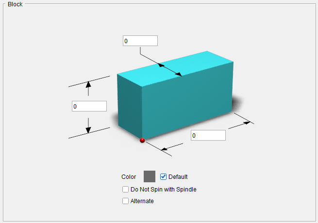
💡 Tip: Hold the cursor over a number field in the tool diagram to see a tip indicating what value the field represents.
Length (L) — Use to specify the length of the block.
Width (W) — Use to specify the width of the block
Height — Use to specify the height of the holder component.
Color — Color that the tool component is to be displayed in Vericut. For additional information, see Tool Display Colors in the Tool Component tab, Common Features section.
Do Not Spin with Spindle — When toggled "on" (checked), indicates that the holder component does not spin.
Alternate — When toggled "on" (checked) this feature designates the holder that is being created as an "alternate" or "secondary" holder for a particular tool assembly. This feature enables you to switch between a "primary" and "alternate" holder shapes.
The AlternateTool macro is used to specify whether to use the "primary" (Override Value = 0) holder shape or to use the "alternate" (Override Value = 1) holder shape.
See Create and Use Tools with Alternate Cutters in the Using the Tool Manager section of Vericut Help for additional information and examples.
See Define a Tool Holder section of Vericut Help for information on creating tool holders.
See Assembly tab section for information on positioning, and orienting, a holder component in a tool assembly.
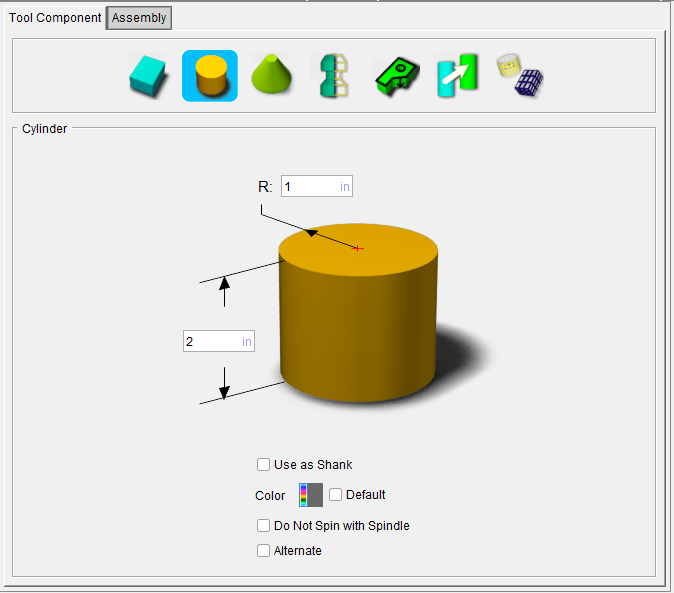
Holder, Cylinder Holder
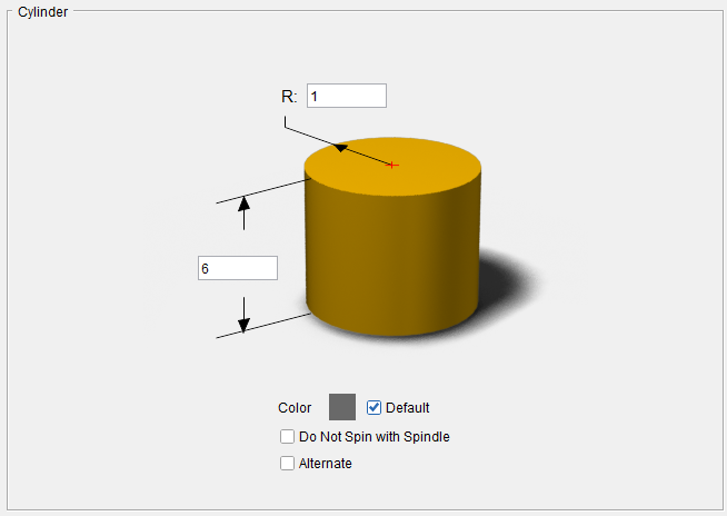
💡 Tip: Hold the cursor over a number field in the tool diagram to see a tip indicating what value the field represents.
Radius (R) — Use to specify the radius of the cylinder.
Height — Use to specify the height of the holder component.
Color — Color that the tool component is to be displayed in Vericut. For additional information, see Tool Display Colors in the Tool Component tab, Common Features section.
Do Not Spin with Spindle — When toggled "on" (checked), indicates that the holder component does not spin.
Alternate — When toggled "on" (checked) this feature designates the holder that is being created as an "alternate" or "secondary" holder for a particular tool assembly. This feature enables you to switch between a "primary" and "alternate" holder shapes.
The AlternateTool macro is used to specify whether to use the "primary" (Override Value = 0) holder shape or to use the "alternate" (Override Value = 1) holder shape.
See Create and Use Tools with Alternate Cutters in the Using the Tool Manager section of Vericut Help for additional information and examples.
See Define a Tool Holder section of Vericut Help for information on creating tool holders.
See Assembly tab section for information on positioning, and orienting, a holder component in a tool assembly.
Holder, Cone Holder
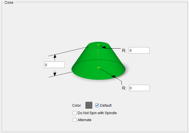
💡 Tip: Hold the cursor over a number field in the tool diagram to see a tip indicating what value the field represents.
Height — Use to specify the height of the holder component.
Top Radius (R2) — Use to specify the radius at the top of the cone.
Bottom Radius (R1) — Use to specify the Radius at the bottom of the cone.
Color — Color that the tool component is to be displayed in Vericut. For additional information, see Tool Display Colors in the Tool Component tab, Common Features section.
Do Not Spin with Spindle — When toggled "on" (checked), indicates that the holder component does not spin.
Alternate — When toggled "on" (checked) this feature designates the holder that is being created as an "alternate" or "secondary" holder for a particular tool assembly. This feature enables you to switch between a "primary" and "alternate" holder shape.
The AlternateTool macro is used to specify whether to use the "primary" (Override Value = 0) holder shape or to use the "alternate" (Override Value = 1) holder shape.
See Create and Use Tools with Alternate Cutters in the Using the Tool Manager section of Vericut Help for additional information and examples.
See Define a Tool Holder section of Vericut Help for information on creating tool holders.
See Assembly tab section for information on positioning, and orienting, a holder component in a tool assembly.