CAMWorks-to-Vericut Interface (CWV)
Overview The CAMWorks-to-Vericut Interface (CWV) is a licensed software utility that enables seamless data transfer from CAMWorks to Vericut. Developed as a SolidWorks macro, this interface operates on top of the CAMWorks application, which itself functions as an integrated add-in within the SolidWorks CAD environment.
Important Note Although, the macro is called from SolidWorks, it will not function if the CAMWorks add-in is not loaded into SolidWorks.
Software Requirements: CAMWorks Interface
Licensing Requirements
CGTech Licensing:
Solidworks Interface
Installation & Configuration: CAMWorks Interface
User Configuration
No manual configuration required
The interface is pre-configured for seamless operation.
Installation Path
The interface installation files are located at:
C:\Program Files\CGTech\Vericut x.x.x\windows64\camworks
Environment variables: CAMWorks Interface
To enable the CAMWorks Interface to locate the necessary Vericut files, the following environment variables are available:
Environment Variables: Description & Example
CGTECH_INSTALL
Purpose: Defines the Vericut installation folder.
Example: For Vericut 9.7, set to: C:\Program Files\CGTech\Vericut 9.7
CGTECH_PRODUCTS
Purpose: Specifies the folder for the operating system running Vericut (windows64).
Example: For Vericut 9.7, set to:
C:\Program Files\CGTech\Vericut 9.7\windows64
LSHOST
Purpose: Defines the name of the license server computer.
Example: localhost
CGTECH_SINGLE_PLATFORM (Optional)
Purpose: Specifies if Vericut is running on a single platform.
Example: CGTECH_SINGLE_PLATFORM=YES
CGTECH_CAMV_ACTIVITY (Optional)
Purpose: By default, activity file is also generated at local 'Application Data' directory inside CGTech/CAMWorks_Interface directory. Example path would be same as that of 'prefs' file. However, by using environment variable CGTECH_CAMV_ACTIVITY user can provide custom path for activity file generation.
Example CGTECH_CAMV_ACTIVITY=C:\Temp
How to add an icon to the CAMWorks Toolbar: CAMWorks Interface
![]()
To set up a Vericut icon in the CAMWorks toolbar, follow these steps:
1. From the SolidWorks toolbar, select the pull-down next to Options icon and select Customize...
![]()
2. Select Commands tab > Toolbars: Macro
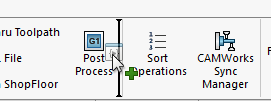
3. Drag and drop New Macro Button  onto the CAMWorks Toolbar
4. Specify the location of the Vericut_Interface.dll
![]()
NOTE: For an Icon you can select:
C:\Program Files\CGTech\Vericut x.x.x\windows64\solidworks\VericutAddin.bmp
5. Select OK
Microsoft Redistributables: CAMWorks Interface
The CAMWorks-to-Vericut Interface (CWV) may require the installation of Microsoft Redistributables, specifically the Windows C++ run-time libraries. These libraries ensure compatibility and proper functioning of the interface, allowing seamless data transfer between CAMWorks and Vericut for manufacturing simulation.
Note: A runtime library is a collection of low-level compiler support routines and functions that are used by virtually all programs compiled with GCC (GNU Compiler Collection) and can be downloaded here.
Documentation: CAMWorks Interface
The CAMWorks-to-Vericut Interface (CWV) is a macro that is designed to work on top of CAMWorks, which already is an add-in working inside SolidWorks. CWV exports the CAMWorks manufacturing data to Vericut. CWV addresses the below Vericut setup requirements and then launches Vericut with the simulation ready to play.
The Vericut simulation requirements are:
1. Select a VMC (Vericut Machine Configuration)
2. Select and orient stock, fixture and design models
3. Select NC Programs & Subroutines
4. Define Cutting tools
5. Define Work Offsets Tables
Accessing the CAMWorks Interface
1. Select the Vericut icon
![]()
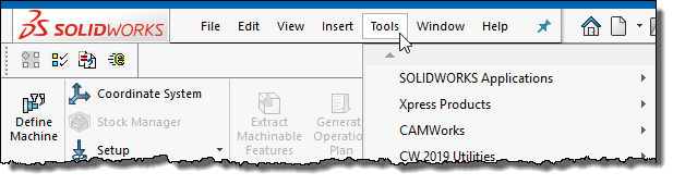
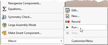
2. Alternately, launch the interface from SolidWorks:
- Click on Tools button into SolidWorks menu.
- Select Macro > Run.
- Browse ‘VERICUT_Interface.dll’.
Important Note: The CAMWorks interface requires an active NC Manufacturing file to function properly with Vericut.
License Handling
- The interface checks out a license when opened.
- The interface checks in the license when closed.
User Interface & Operation
When you trigger CWV, either with the toolbar icon or from the SolidWorks menu, you should see a window similar to this:
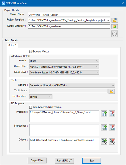
Project
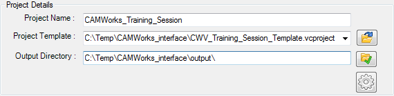
Project Name – Project name for the output Vericut files is entered here. By default, name of the current CAMWorks project file is used.
Project Template – “path/filename” of an existing project template file can be specified here. Alternatively, browse button  can be used, as well, to open file browse & selection window to locate the template file. Each selected file of the session gets added into pull-down list and ultimately to global preference data, hence user can also have option to expand pull-down list and select desired file instead of re-browsing operation.
Output Directory – “\path\” of the directory where user wants to output all Vericut files can be specified here or user can also use the browse button  to open a directory browse & selection window to locate the directory path.
Preferences Dialog – Pressing button  opens up ‘Preferences’ dialog where use can provide global settings related to interface behavior. By pressing ‘Ok’ user can confirm the settings. As soon as user hits ‘Ok’ dialog gets closed and all the settings gets reflected on the interface.
The area below ‘Output Directory’ is used as error logger area, which displays any relevant warning or errors information during operation.
Setup Details
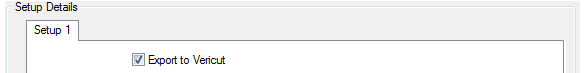
In the case of multiple setups, user can choose not to output particular setup data and export to Vericut by de-selecting this check box. By default, the Export to Vericut checkbox is checked for each setup.
Attachment Details
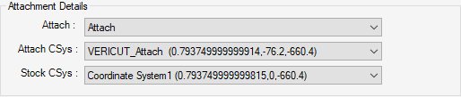
Attach Component – Attach component’s list is populated by parsing machine file, defined in project template file. Selected component acts as “Attach Component” for the stock into Vericut.
Attach CSys – The list displays, names of all the coordinate systems defined into CAMWorks project file. Selected coordinate system would be used to locate stock and fixture models on to machine in Vericut.
Stock CSys – Stock coordinate system is used to reorient stock model into next setup from the current one.
Note: The ‘Attach CSys’ and ‘Stock CSys’ pull-down list consist of all the coordinate systems defined in the Solidworks feature tree and also in all the operation configuration of CAMWorks. In the case of the assembly, coordinate systems defined in all individual parts are also parsed and displayed into these pull-down lists.
Tools
The User has to make a decision from one of the options for tools to export to Vericut from pull down list.
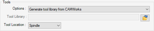
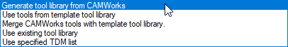
Options:
-
Generate tool library from CAMWorks
With this option selected, the CAMWorks-to-Vericut interface generates a tool library file from the information coming out from CAMWorks and the provided tool template file. Tool template file path-name is obtained from the project template file. -
Use tools from template tool library User can choose to not export any tools from CAMWorks and continue with tools defined in tool template file. As mentioned earlier, tool template file can be defined into project template file.
-
Merge CAMWorks Tools with Template Tool Library: Choose this option to merge the tool library created by the CAMWorks-to-Vericut Interface, with the tool library file stored in the Setup Template, and use the \"merged\" tool library rather than one created by the CAMWorks-to-Vericut Interface.
-
Use existing tool library User can also use existing tool library. Having this option selected, text-box below the pull-down list Tool Library, will get enabled. Here user can browse and select desired file.
-
Use specified TDM list Apart from all above-mentioned options, user can also have option to specify TDM list, which will be exported to Vericut.
-
Tool Location This pull-down list gives user an option to specify whether tools are going to be attached to 'Turret' or 'Spindle'. Choice of 'Turret' or 'Spindle' plays crucial role in deciding orientation of the tools.
NC Programs
‘NC Programs’ section includes three difference sub-sections to specify Programs, Subroutines and G-Code Work-Offsets.
Programs
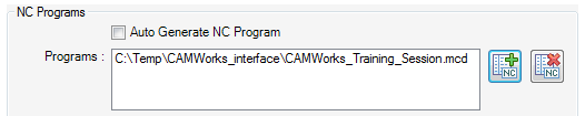
Check button is provided if the user wants to Auto Generate NC programs using post-processors defined in the CAMWorks. As an additional option, user can also locate existing NC programs. ‘NC Programs’ list displays the NC programs those are going to be passed to Vericut. ‘Add’  and ‘Delete’ buttons are provided to add and remove NC programs to the list.
Subroutines
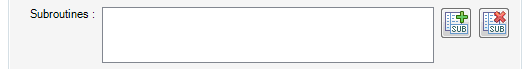
The ‘Subroutines’ list displays the subroutines specified to be passed to Vericut. Similar to NC programs, the ‘Add’  and ‘Delete’ buttons are provided to enable adding/removing subroutines to/from the list.
Offsets
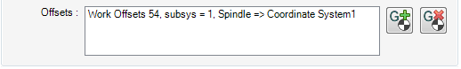
‘Offsets’ list displays the list of currently defined offsets.
Add  – Opens up ‘Offsets’ dialog (as shown in the picture below) giving user an ability to define new offset or to modify existing ones.
Delete  – Deletes the selected offset record from the ‘Offsets’ list.
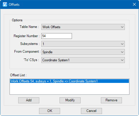
Table Name – The Table name pull-down list contains the following Vericut G-Code tables: ‘Program Zero’, ‘Work Offsets’, and ‘Base Work Offset’. Selected table name is used to identify the type of the offset table to be added or modified.
Register Number – Register number value has to be integer value. In case of invalid entry by the user, an error message in red font appears alongside of the text field. The register number is used by Vericut to access corresponding table data.
Subsystems – Subsystem names are populated from the Vericut machine file, defined into ‘Project’ template file.
‘From’ Component – ‘From’ component list is made of all machine components defined into machine file. Selected component is used for determining origin point of the offset.
‘To’ CSys – ‘To’ CSys list consist of all coordinate systems defined into all CAMWorks operations. It will also include coordinate systems defined into SolidWorks feature tree. In the case of the assembly, coordinate systems defined in all individual parts are also parsed and displayed into this pull-down list. Selected component is used for determining destination point of the offset.
Delete  – Deletes the selected offset record from the 'Offsets' list.
Generate buttons
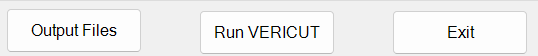
Output Files: If user chooses to output Vericut files without launching Vericut, it can be achieved with the use of ‘Output Files’ button.
Run Vericut: ‘Run Vericut’ button is provided to output all Vericut files and launch Vericut with newly created files. User’s project specific settings are saved into settings file right before outputting files.
Exit: The ‘Exit’ button is provided to exit the interface. But before invoking exiting event, interface updates preference file with latest user changes.
Preferences
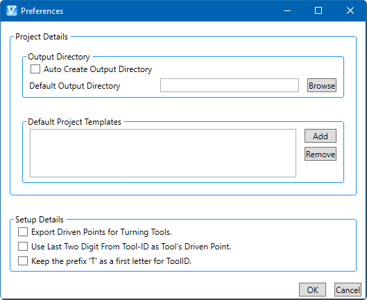
‘Preferences’ dialog mechanism is given to specify global options for interface display & behavior. These user options are global and are applicable to all sessions of the interface following, including the current. User options are stored in local ‘Application Data’ directory.
Example path would be:
C:\Users\username\AppData\Roaming\CGTech\CAMWorks_Interface
Similar to main interface dialog, ‘Preferences’ dialog is also divided into two main parts; Project Details and Setup Details.
Activity File
The CAMWorks -to-Vericut interface will do its best to ensure a valid operation sequence, but when something does go wrong, an entry is added to the Activity File. Any attempt to execute an unsupported operation will also be recorded here. At last, any undesirable behavior of the CAMWorks-to-Vericut Interface software is also recorded here.
The Activity File is located at:
C:\Users*username*\AppData\Roaming\CGTech\CAMWorks\vericut_addin_activity.txt
In the event of reporting a problem to CGTech technical support, it would be desirable to have 'Activity file' along with any example file. This will greatly expedite the process of resolving the problem.
By default, activity file is also generated at local 'Application Data' directory inside CGTech/CAMWorks_Interface directory. However, by using environment variable CGTECH_CAMV_ACTIVITY user can provide custom path for activity file generation.