Project Tab
The Project tab contains various features related to Project Tree, tools, setups, displays, and various other features. All features will be summarized on this page but each hyperlinked feature can be clicked on to see a more detailed description for more information.
Project group
-
Project Tree — opens the Project Tree panel enabling you to manage all files related to running your Vericut project.
-
Tools — opens the Tool Manager window enabling you to manage your tools.
-
Tool Change List — opens the Tool Change List panel enabling you to maintain a list of references that link tool change events to tools stored in the current Tool Library file.
-
Settings — opens the Settings window enabling you to configure various settings for several features.
-
Variables — opens the Variables panel where you can monitor, initialize, and maintain G-Code variables.
-
Offsets — opens the Offsets panel enabling you to add, modify, and delete G-Code Offsets.
Setup group
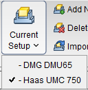
- Current Setup — displays a pulldown list of all available Setups. A check mark is displayed next to the current setup (see below). Clicking on a setup in the list will make it the current one. Inactive setups are displayed in red text.
- Add New Setup — appends a new setup after the current setup. The new setup will become the current setup.
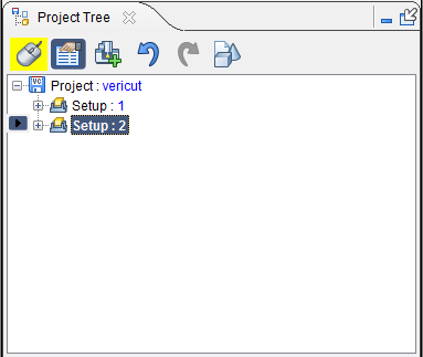 |
Before using Add New Setup, Setup 2 is the “current” setup. |
|---|---|
 |
After using Add Current Setup, Setup 3 is added and becomes the “current” Setup. |
- Delete Current Setup — removes the current setup and makes the next setup in the list the current setup. If the setup at the end of the list is deleted, then the previous setup becomes the current setup. There must always be at least one setup in a project. Therefore, the last remaining setup cannot be deleted.
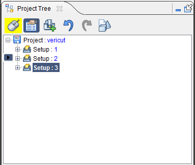 |
Before using Delete Current Setup, Setup: 3 is the "current" setup. |
|---|---|
 |
After using Delete Current Setup, Setup: 3 is deleted and Setup: 2 (the next in the list) becomes the "current setup. |
- Import Setup — opens the Import Setup window enabling you to copy a setup from another project and append it after the current setup.
Simulation Settings group
- No Animation — turns off all animation. This reduces processing time. No Animation can be toggled on or off while the simulation is running. When No Animation is toggled "on", the graphics display is not updated until either processing is complete or you Stop the processing. At that time the cut model is displayed in it "final" state or the state that it was in when processing was stopped. You can also toggle No Animation On/Off using the No Animation icon in the Vericut toolbar.
-
Resolution — controls the quality of cut model display. Increasing resolution displays a more accurate representation of the cut model, and requires more computer resources and processing time to display and manipulate the model. A coarse display resolution is automatically used when dynamically manipulating the model, such as rotation, zooming, etc. When the dynamic action is finished, the display is upgraded to the previous resolution. Options:
-
Manual — A display resolution which allows most models to be manipulated with acceptable performance and display quality.
-
Auto — Automatically sets display resolution based on viewing distance from the model. Resolution automatically increases when you zoom closer to see details on the model, and decreases as you zoom out.
View Controls group
-
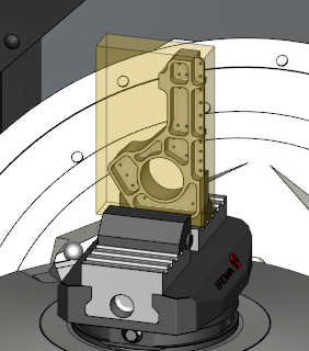
Stock/Design View — displays translucent Stock and solid Design, regardless of the component translucency settings. When the user clicks out of this temporary view state, then the component/model visibility goes back to what it was before that option was engaged. This feature can also be accessed from the View tab. Here is an image of an active Stock/Design view:
-
Section — opens the Section window enabling you to define section planes through a Vericut model in a workpiece view. You can also define a section wedge through a Vericut model in a workpiece view.
- Refine Display — improves the image quality in the Graphics Area.
-
Reverse — inverts the view of the displayed model.
-
Axes — opens the View Axes enabling you to control when various axes and coordinate systems are displayed.
-
 Single View Layout — Use to change the layout of View windows to a single window.
 -
 Two View Layout (Horizontal) — Use to change the layout of View windows to two windows arranged side by side.
 -
 Two View Layout (Vertical) — Use to change the layout of View windows to two windows arranged top to bottom.
 -
 Zoom to Box — Use to zoom into a selected area. Select Zoom to Box then left click in a View area and drag the mouse to create a box. The view automatically zooms into that box once the left mouse is released.
 -
 Zoom Box in New View — Use to zoom into a selected area with the selected area becoming a new View window. Functions identically to Zoom to Box.
 -
 View Orthogonal — Snaps the current view to the closest orthogonal view.
 -
 Fit — Use to maximize the view of the stock workpiece. Select an active view then select Fit. The workpiece in the active view will then fill as much of the window as possible while still fitting entirely within the window frame.
 -
 Fit Selected (All Views) — Similar to Fit, above, but applies to all active views.
Utilities group
-
Active Coordinate System — sets the active CSYS that Vericut uses for simulating NC program motions, X-Caliper measurements, and sectioning models. If Display Active Coord. Sys., in the Project tab > View Axes window, is toggled "on" (checked), a coordinate system with the name of the active coordinate system will display in the Vericut graphics area as shown in the picture below. Only the "active" coordinate system will have the marker displayed at its origin as shown in the picture. By default, the active coordinate system will be set at Machine Origin. Use the Configure Coordinate System menu to create additional coordinate systems.
-
MDI — opens the MDI window enabling you to manually enter and process blocks of G-Code data.
-
Delete Detached Stock — opens the Delete Detached Stock window enabling you to delete or keep pieces of material.
-
Load All Stocks — causes Vericut to load new stock models for Stock components having models defined, but a cut stock model does not exist.