Configuring Other Interfaces
Configuring the Vericut TDM Systems Interface
Vericut has the ability to connect to both TDM databases that TDM Systems currently offers:
-
TDM (commonly referred to as “V4” or TDM “Classic”)
-
TDM Global Line
The determination of which Vericut to TDM Interface to use will depend on which TDM tool data management system you are intending to connect with. Both the TDM Interface and TDM Global Line Interface are separate optional licenses that are necessary to connect to the appropriate TDM database.
Configuration of the TDM Interface (commonly referred to as “V4” or TDM “Classic”)
Vericut connects to the TDM Systems tool management database using a Dynamic Link Library (DLL) supplied by TDM Systems. It is mandatory to use the DLL supplied with your specific TDM installation since the DLL is both specific to the TDM version and to the Oracle database version. The following steps must be followed to configure the installation in order for the TDM icon to activate in Tool Manager.
This TDM Interface will use the following TDM Icon in Tool Manager. By default this icon will be greyed out until your computer is configured per the steps below.
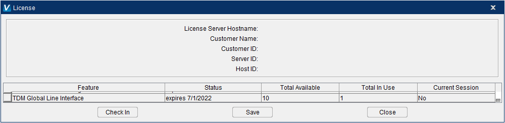
Check to ensure the customer’s license includes the optional TDM Interface license in Vericut. This license is necessary to connect to the TDM database. To do this, launch Vericut > Help ribbon > License. Scroll down and find ‘TDM Interface’. If this license is not listed, contact your local CGTech representative.
The following environment variables need to be set in your local computer:
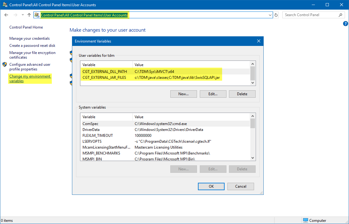
Variable Name: CGT_EXTERNAL_JAR_FILES
Path: c:\TDM\java\classes;C:TDM\java\lib\SwisSQLAPI.jar

CGT_EXTERNAL_JAR_FILES environment variable is setup manually on your local computer to point to the following locations. Both paths are necessary.

  c:\TDM\java\classes

  C:TDM\java\lib\SwisSQLAPI.jar
Variable Name: CGT_EXTERNAL_DLL_PATH
Path: C:\TDM\Sys\iMVCT\x64

CGT_EXTERNAL_DLL_PATH environment variable is setup manually on your local compute to point to the location in TDM where the .dll’s and .ini files are located.
When these edits are completed, Vericut’s TDM Interface can then be invoked from the **Tool Manager > Import ribbon > 
Alternately, the previous method of modifying the vericut.bat file and copying the .dll files and tms.ini files into the appropriate folder will work to successfully configure the TDM Interface to Vericut but it is strongly recommended to use the above configuration process going forward. Please contact TDM or CGTech’s technical support for more information regarding this configuration.
Configuration of the TDM Global Line Interface
Vericut connects to the TDM Global Line tool management database using an https address along with a Username and password. This interface does not need any modification of the vericut.bat or toolman.bat files nor any .dll files or tms.ini files.
This TDM Global Line Interface will use the following TDM Icon in Tool Manager. By default this icon ![]() is active.
is active.
Check to ensure the customer’s license includes the optional TDM Interface license in Vericut. This license is necessary to connect to the TDM database. To do this, launch Vericut > Help ribbon > License. Scroll down and find ‘TDM Interface’. If this license is not listed, contact your local CGTech representative.
Click the TDM Global Line icon to invoke the TDM Global Line Interface.
The first time the TDM Global Line Interface is opened enter the following information into the appropriate fields at the top of the interface:
-
User
-
Password
-
Base URl
Once the correct information is entered click Connect. Upon a successful connection the light will turn green and the User, Password, and Base URl will be stored in an encrypted .config file within Windows.
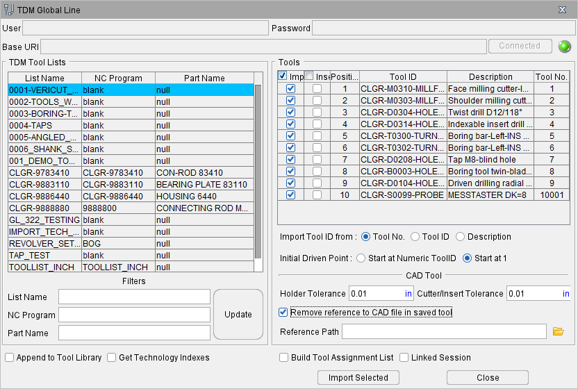
Subsequent activation of the TDM Global Line Interface icon will automatically recall the encrypted User, Password, and Base URl information and populate the appropriate fields. The user only needs to click Connect to use the TDM Global Line Interface.
Configuring WinTool Interface
Vericut has the ability to easily use 3D tooling generated from WinTool, an independent tool database management system. WinTool is an independent tool database management system.
WinTool generates a .tls file for use in Vericut’s Tool Manager. This .tls file can be generated independently from Vericut or from launching the WT-Tool Export executable (for example "C:\Program Files (x86)\WinTool\WT-Vericut-Interface\WT-ToolExport.exe") via the WinTool icon from Tool Manager’s Import ribbon.
The WinTool icon in Vericut’s Tool Manager is inactive, by default. Installation of the WinTool tool data management software is a requirement in order to use the WinTool icon within Tool Manager. The icon will automatically become active if WinTool software is installed and one of the following criteria are met. These criteria are checked in the following order:
-
‘CGTECH_WINTOOL’ environment variable (should be defined during WinTool installation)
-
.exe file path is set in Vericut Tool Manager’s Preference dialog under CAD Tool Import Executables section
- Windows registry (should be defined during WinTool installation)
The WinTool configuration and installation instructions are part of the WinTool install documents by WinTool AG. For further details on the WinTool WT-ToolExport interface see the WT-Vericut-Interface-Manual-E.pdf (for example: C:\Program Files (x86)\WinTool\WT-Vericut-Interface\Docs\WT-Vericut-Interface-Manual-E.pdf) or contact WinTool.
Per the WinTool installation instructions the following line needs to be added to the vericut.bat and toolman.bat files. This line can be added anywhere in the .bat files.
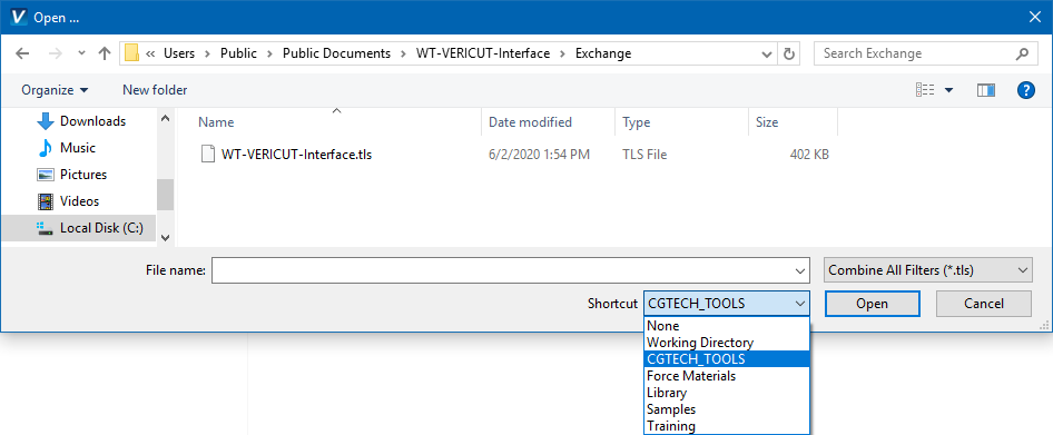
set CGTECH_TOOLS=C:\Users\Public\Documents\WT-Vericut-Interface\Exchange
Adding this variable to the .bat files will provide a Shortcut to the location where the WinTool .tls files are created.
Configuring ZOLLER Interface
The ZOLLER Interface to Vericut allows for configuration for different options depending on the users needs and setup with ZOLLER TMS.
Prioritization/Control of Graphics
The ZOLLER Interface can be configured to control the priority and limitation of graphics to be read from the ZOLLER TMS database. This configuration is optional and ONLY for situations where the user needs to prioritize the order of graphics to be read into Vericut’s Tool Manager that does not follow the default order of graphics.
By default the ZOLLER Interface will look for and read the following graphic file formats for each tool type from the ZOLLER TMS database.
For milling/drilling (spinning) tools:
-
SVG Contour (similar to a DXF)
-
(If SVG Contour does not exist) .STEP/.stp file located in ‘GraphicFile’
For turning tools:
- .STEP/.stp file located in ‘GraphicFile’
The ZOLLER database has the option to contain up to 10 types of graphics files for each tool assembly to read 3D graphics models from. These nine graphics are displayed in the ZOLLER TMS software as shown below in the ZOLLER window.
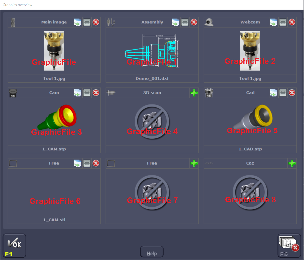
-
Main_Graphics
-
Assembly
- Webcam
- CAM_3D
- Scan_3D
- CAD_3D
- Free
- Free2
- CAZ
The SVG Contour is the 10th graphics file option within ZOLLER TMS. It is a 2D format, similar to a DXF file. It is not displayed in the above ZOLLER TMS dialog nor is it configurable with the environment variables listed below.
If the user needs to prioritize or limit the order of graphics being read in for tool assemblies through the ZOLLER Interface, there are environment variables that can be used to control these preferences. These environment variables are preconfigured in a cgt_zoller.bat file in the installation of Vericut - (installation of Vericut)\windows64\commands\cgt_zoller.bat. This set of default preconfigured variables are what ZOLLER recommends to start with should they be needed.
To utilize this cgt_zoller.bat file, edit the vericut.bat and toolman.bat files and remove the “rem” next to the following line:
rem call "%CGTECH_PRODUCTS%\commands\cgt_zoller"
Removing the “rem” will reference this cgt_zoller.bat file when launching Vericut or stand alone Tool Manager.
Edit the vericut.bat and toolman.bat files in a text editor. It is strongly recommended to make copies of all files described below prior to the edits and changes. The original files can be used for comparison in case there is an issue.
Within the cgt_zoller.bat file:
-
For milling/drilling (spinning) tools - CGTECH_ZOLLER_MILL_TOOL_ORDER
-
For turning tools - CGTECH_ZOLLER_LATHE_TOOL_ORDER
The line labeled “REM -Used variables-…” consists of the exact syntax for each graphic should they be needed. In this line they are listed in the order of the 3 x 3 graphics window shown above.
The order in which the items appear in the list is the order in which the items will be checked. If a GraphicFile name is not listed next to the environment variable it will not be read.
Color Settings for Graphics
STEP models within ZOLLER TMS should be defined with the correct ISO color standards in order for the interface to correctly recognize CUT, NOCUT, NOCUT NOSPIN components correctly.
The following are the ISO color standards:
-
CUT = RGB Value 205 | 205 | 205
-
NOCUT = RGB Value 128 | 128 | 128
-
NOCUT NOSPIN = 141 | 141 | 141
If a user needs to adjust the ZOLLER Interface to read color changes that were made in their ZOLLER TMS, this can be done by utilizing the following environment variables in the cgt_zoller.bat file. There are individual color settings for the CAD and CAM files. The default values displayed next to each variable are the recommended start settings from ZOLLER.
CAD
set CGTECH_ZOLLER_CAD_CUT=255,215,0

set CGTECH_ZOLLER_CAD_NOCUT=165,169,190

set CGTECH_ZOLLER_CAD_SHAFT=75,75,75

set CGTECH_ZOLLER_CAD_NOCUT_NOSPIN=128,64,0
CAM
set CGTECH_ZOLLER_CAM_CUT=255,0,0

set CGTECH_ZOLLER_CAM_NOCUT=0,128,0

set CGTECH_ZOLLER_CAM_SHAFT=255,255,0

set CGTECH_ZOLLER_CAM_NOCUT_NOSPIN=128,64,0
Installing the Model Interface Modules
The Model Interface modules (CATIA V4 Model Interface, CATIA V5 Model Interface, STEP Model Interface, and ACIS Model Interface) enable Vericut to both read and, when combined with Model Export, write the designated model file formats. These modules do not require a CAD/CAM system be available for Vericut to read or write any of the formats. The modules are available for Windows 64 bit platforms. Each module is licensed separately.
Model interfaces are installed from a separate installer executable (not part of the Vericut installer). The Model Interface installer is available for download from Vericut’s website, and it is also distributed on the Vericut 9.7 installation. To download the model interface installer appropriate for your current Vericut installation:
-
Click on the appropriate link below to start the download of the model interface installer for your Vericut version:
https://vericut.com/products/vericut-latest-release -
Unzip the model_interfaces_vx.x.x.zip file (where x.x.x is the Vericut release number) to extract the installer executable to a folder.
To start the installation:
Double-click on installer executable (either the downloaded installer executable from step 2 above, or the installer executable on the Vericut 9.7 DVD) to display the Installer window. Follow the instructions in the Installer to complete the installation process. Make sure to select the correct Vericut installation folder, for example C:\Program Files\cgtech\Vericut 9.7
📝 NOTES:
-
You may need to have the latest Microsoft Windows updates installed (as of August 14, 2009) for the CAD Model Interfaces to work correctly.
-
If you get the following error message "Error loading ACIS libraries!", or no error message at all try installing the Microsoft redistributable C++ run-time libraries. See the Install Microsoft redistributable C++ Run-Time Libraries topic above for additional information. You must have Administrator privileges to do the install.
Vericut's CAD Model Interface modules should now be available if you are licensed to use them.
If errors occur, contact Vericut technical support via our website, just click on the support link.
Commuter Tool
The "CGTech Commuter Tool" is a utility to check out\in (borrow) licenses. A commuter license allows users to borrow a license from their license server to continue to use Vericut while away from their own network. Or when they need or forced to work offline. Commuter licenses can be borrowed for a max of 14 days, and it will be subtracted from number of licenses that are available on the license server. Commuter licenses can be checked back in anytime before the borrow expiration time. Expired borrowed license will be automatically checked into the license server.
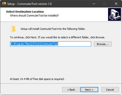
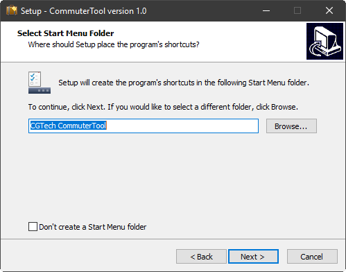
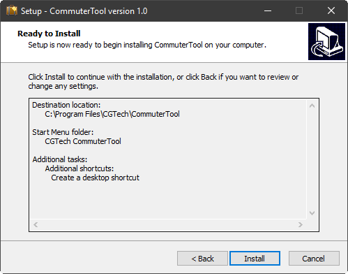
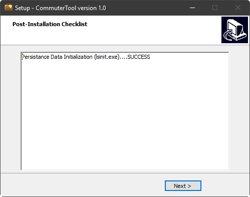
Installation
Run commuter_tool_install.exe
Step through install (📝 NOTE: Administrator rights are required.)
-
Select language
-
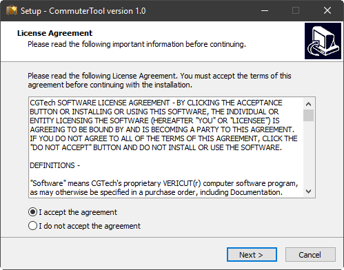
License Panel
-
Install Location Panel
-
Program Menu Group Panel
-
Shortcuts Panel

-
Install… Panel
-
Post-install (lsinit.exe check) Panel
-
Complete Panel

CGTech Commuter Tool
Run commuter tool from start window
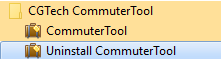
or from Desktop icon ![]()
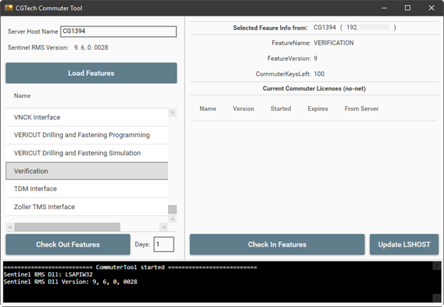
Server Host Name — Specify the server host name or the IP address.
Load Feature — Loads the license keys that are allowed to be commuted.
License keys that are not allowed to be commuted will gray out.
Checking Out Features — This bottom checks out all the different license keys that a user selected Enter the Host Name.
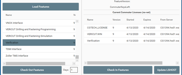
Days — Specifies the number of days a license can be selected, minimum 1 maximum of 14.
Update LSHOST — This will update [Vericut Install Directory]\windows64\commands\cgtenv.bat file to include the line: "set LSFORCEHOST=no-net"
📝 NOTE: Once a commuter license is checked out it will be unavailable on network License Server for the remainder of the days that it was checked out for or until it is manually checked back in to the network License Server.
Checking In Features — Allows user to manually check in borrowed unexpired licenses.
[Vericut Install Directory]\windows64\commands\cgtenv.bat file will be reverted back to its original state if all CGTech commuter licenses have been checked back into the server.
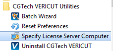
📝 NOTE: If borrowed license Expired user will have to manually edit [Vericut Install Directory]\windows64\commands\cgtenv.bat file or use the Specify License Sever Computer from the CGTECH Vericut Utility xx menu in Windows Start menu.