Attributes (View Attributes window)
Location: View tab >  (Attributes)
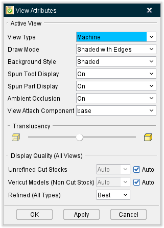
The Attributes command button opens the View Attributes window enabling you to control the attributes of a view, such as: what is seen in a view, light source, shading, etc. In general, click in a view to make it active, then change attributes as required. Each view has its own view attributes. The features on the View attributes window will vary slightly depending on whether the review file was created Vericut Simulation, Vericut Composite Simulation or in Vericut Drill and Fastener Simulation.
View attributes add to visualization power by enabling you to:
-
Change what is seen in a view: workpiece machining, machine motions without machining, or machining a workpiece on a machine.
-
Show machines in shaded or wireframe display.
- Control light direction.
- Change the background, including ability to add walls and a floor in a view of an NC machine.
Each view has its own individually controlled attributes.
Vericut Simulation Review files
VCS and VDAF Review files
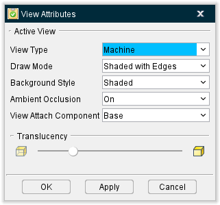
View Type — Controls what is seen in a view. Options are:
-
Workpiece — Displays the stock workpiece and machining that occurs on it. This view supports X-Caliper measurements. This feature is only available for review files created in Vericut Simulation.
-
Form — A Form view displays the form and composite material as it is applied. This feature is only available for review files created in Vericut Composite Simulation.
-
Machine — In Vericut Simulation review files, a Machine view displays the NC machine, when defined. The uncut stock can be seen, however, material removal does not occur in this view type.
In Vericut Composite Simulation review files, a Machine view displays a 3-D composite tape laying machine or robot with a composite tape laying head, the form and the composite material as it is applied.
In Vericut Drill and Fastener Simulation review files, a Machine view displays a 3-D drilling/fastener machine or robot with a drilling/fastener head, the skin and the drilled holes and fasteners as they are inserted. -
Machine — Same as above, except material removal does occur. (Does not support machined part inspection-use a Workpiece view type for this activity.) This feature is only available for review files created in Vericut Simulation.
-
Profile — Displays a 2-D profile view of a turned workpiece in a G-Code NC program simulation, as if it were spinning and sectioned along the turning axis. The profile is created when cutting begins. This feature is only available for review files created in Vericut Simulation.
📝 NOTE: Ensure a Spindle component is defined in the machine and turned on by codes in the G-Code NC program file.
↘️ Shortcut: You can quickly change the View Type by right-clicking in the view, and selecting from the displayed menu. See the Graphics Area Right Mouse Button Shortcut Menus, in the Getting Started section of Vericut Reviewer Help for more information.
See Changing the View Type under Using the View Attributes window, also in the View tab section of Vericut Reviewer Help for additional information.
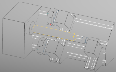
Draw Mode — Controls how machine components are displayed. Options:
-
Shaded with Edges —
-
Shaded —
-
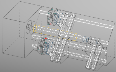
Hidden with Edges Removed —
-
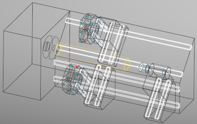
Hidden Edges Shown —
-
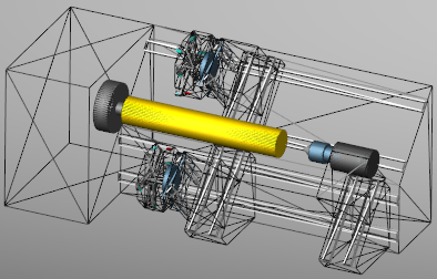
Wireframe —
-
Polygon Wireframe —
↘️ Shortcut: You can quickly change the Draw Mode by right-clicking in the view, and selecting from the displayed menu. See the Graphics Area Right Mouse Button Shortcut Menus, in the Getting Started section of Vericut Reviewer Help for more information.
See Changing How a Machine is Displayed under Using the View Attributes window, also in the View tab section of Vericut Reviewer Help for additional information.
Background Style — Controls the background seen in a view. Options:
-
Flat — The view background is Monochromatic.
-
Shaded — The view background varies from light-to-dark shading.
↘️ Shortcut: You can quickly change the Background Style by right-clicking in the view, and selecting from the displayed menu. See the Graphics Area Right Mouse Button Shortcut Menus, in the Getting Started section of Vericut Reviewer Help for more information.
See Changing the View Background under Using the View Attributes window, also in the View tab section of Vericut Reviewer Help for additional information.
Spun Tool Display — Choose between On and Off options to determine if tools will indicate when they can spin.
Spun Part Display — Choose between On and Off options to if other parts will indicate when they can spin.
Ambient Occlusion — When active, approximates how bright light should be shining on specific surface parts.
View Attach Component — Attaches the view point and line of sight for a view to the selected component. By default, a Workpiece view is attached to a Stock component, thus the workpiece remains stationary while the tool moves about it. Similarly, by default in a Machine view the view is attached to the machine's Base component, thus the machine base appears stationary while its axes move. Whatever component is selected as the attach component becomes stationary in the simulation, while all other objects are simulated as moving relative to that component.
Shortcut: You can quickly change the component the view is attached to by right-clicking in the view, and selecting Attach Component in the menu that displays. See the Graphics Area Right Mouse Button Shortcut Menus, in the Getting Started section of Vericut Reviewer Help for more information.
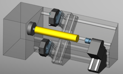
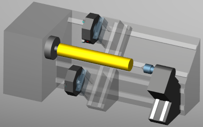
Translucency — Controls when the stock model is displayed as translucent (can be seen through). Slide the slider all the way to the left to make the model completely translucent or slide it all the way to the right to make the model completely opaque.
Display Quality — This feature is only available in Vericut Simulation Review files.
-
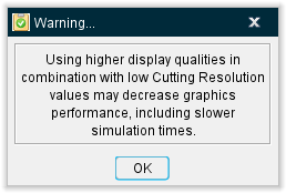
Unrefined Cut Stocks — Use this option to control the quality of cut stocks. This feature is automatically set to Auto but can be toggled off (not checked) to use the dropdown menu to select between options of Best, High, Medium, and Low. Turning off Auto generates the following warning:
-
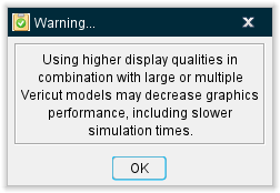
Vericut Models (Non Cut Stock) — Use this option to control the quality of Vericut models. This feature is automatically set to Auto but can be toggled off (not checked) to use the dropdown menu to select between options of Best, High, Medium, and Low.Turning off Auto generates the following warning:
OK — Applies the changes and closes the View Attributes window.
Apply — Applies the changes and leaves the View Attributes window open.
Cancel — Closes the View Attributes window without applying changes.
Using the View Attributes window
Changing the View Type
Vericut Reviewer enables you to see machining in a variety of ways. Each view is capable of displaying the workpiece being machined, the NC machine, or a "combined" view of the workpiece being cut on the NC machine.
To change the view type to display a workpiece, machine, or combined view:
-
Click in the view that you want to change the view type so that it becomes the "active" view.
-
Use one of the following methods to change the type of view:
-
In the View Attributes window (View tab > Attributes in the Vericut Reviewer main menu ribbon), select the desired view type (Workpiece, Machine, or Profile) from the View Type pull-down list.
-
Right click in the view and select View Type > type (Workpiece, Machine, or Profile) from the menu that displays.
📝 NOTE: A 3-D machine must be defined for it to be seen in a Machine view.
Also see Graphics Area Right Mouse Button (RMB) Shortcut Menus section of Vericut Reviewer Help for additional information on the features available when you right click in a view.
Changing How a Machine is Displayed
Vericut Reviewer can display a 3-D machine in many ways: shaded solids, wireframe, hidden lines, etc. How the machine is displayed has no effect on the accuracy of the simulation or collision checking. However, the way that it is displayed can affect performance. The effect varies, depending on your hardware configuration, and complexity of the machine/workpiece.
To change how the machine is displayed:
- Click in the Machine view containing the machine display that is to be changed so that it becomes the "active" view.
- In the Vericut Reviewer main menu ribbon, click on View tab > Attributes to display the View Attributes window.
-
In the View Attributes window, choose the desired Draw Mode for the machine from the pull-down list.
-
Press Apply to apply the change and leave the View Attributes window open for additional work, or OK to apply the change and close the View Attribute window.
Changing the View Background
Vericut Reviewer offers several background types for views. The choice of background has no effect on simulation speed or accuracy, but can make the simulation appear more attractive or realistic.
To change the background in a view:
Choose one of the following methods to change the view background:
Use the View Attributes menu
-
Click in the view that you want to change the background style so that it becomes the "active" view.
-
In the Vericut Reviewer main menu ribbon, click on View tab > Attributes to display the View Attributes window.
- In the View Attributes window, select the desired background style from Background Style pull-down list.
Use a view right mouse button menu
-
Right click in the view that you want to change the background style.
-
In the menu that displays, select Background Style > style (Flat or Shaded). The styles available will vary depending on the View Type. This feature is not available for Profile Views.