Animation Controls

The Animation Controls features, located at the bottom of the Vericut main window, enable you to control and visually monitor certain events related to the simulation. The Animation Controls consist of the following key features:
-
Statuses — Enables you to visually monitor certain events associated with the simulation (status of travel limit checking, collisions, probing, subroutines, cutter compensation, cycles, motion, Optimization, and when Vericut is processing).
-
Simulation Controls — Enables you to start, single step, stop, rewind, and reset the Vericut simulation.
-
Animation Speed Slider — Enables you to control the speed of the simulation.
Each of these Animation Controls features is described in detail in the following sections.
💡 Tip: Use the key F1 for Help on the Animation Controls features. When undocked click anywhere in the Animation Controls features bar to give it focus, then F1. When docked, you can also get to the Help if you click on the Animation Slider to give the Animation Controls bar focus, then F1.
Temporary Messages/Prompts — Many of Vericut’s functions output temporary messages or prompts to assist you with using the feature. These messages and prompts are displayed in the space below the Animations Control features as shown in the picture above.
Statuses
The "Statuses", located on the left hand side of the animation controls, provide constant visible feedback over when Vericut is processing certain events, busy performing a task, or optimizing an NC program file. The function and conditions represented by the color of each status light is described below.

Ready — Indicates Vericut Status.
-
Red — indicates that Vericut is "Busy" processing.
-
Yellow — indicates that Vericut is "Paused" in the middle of a block or cycle.
-
Green — indicates that Vericut is "Ready" for user commands.
Optimize — Indicates Optimization status.
-
Green — indicates Optimization is "On".
-
Yellow — indicates Optimization is in "Learn Mode".
-
Dark Green — indicates that Optimization is "Off".
Collision — indicates the status of collision checking.
-
Red — indicates that a collision occurred on the current block.
-
Yellow — indicates that a collision has occurred during the current session.
-
Green — indicates that Collision Detection is toggled "On".
-
Dark Green — indicates that Collision Detection is toggled "Off".
Limit — indicates the status of travel limit checking.
-
Red — indicates that a travel limit has been exceeded on the current block.
-
Yellow — indicates that a travel limit has been exceeded during the current session.
-
Green — indicates when Overtravel Detection On is toggled "On".
-
Dark Green — indicates that Overtravel Detection On is toggled "Off".
Simulation Controls

The simulation controls, also known as VCR buttons, located on the right end of the Animation Controls features, control interactive tool path simulation. Once Vericut is configured, you will use these controls to start and stop the simulation, as well as begin with a new, uncut workpiece. To see what is associated with a Simulation control icon, simply position the cursor over the icon and a tip appears. In addition, holding the cursor over the Play/Start-Stop Options button  , or the Step / Subroutine Options button
  , turns the lower right corner red indicating that these buttons have a secondary function. Right click on these buttons to access the secondary function. Right click on the button again to dismiss the secondary function. Messages and tips associated with these buttons will display in the bottom right corner of the window next to the Info alert icon
 ![]() .
.
Each of the simulation controls buttons is described below.
Simulation controls:
| Icon | Name | Function |
|---|---|---|
 |
Reset Model | Display a new Vericut model and rewind the NC program file. The Reset Confirmation will display. |
 |
Rewind NC Program | Rewind the NC program file to the beginning (leave the model as is). |
|
Play / Start-Stop Options | Left click — start or re-start NC program processing. Tips: 1. Left click on the Play icon while simulating to stop the simulation just like using the Pause icon. 2. Once you have clicked on the Play icon with the left mouse button, you can pause and start the simulation by using the spacebar. The spacebar will repeat the last mouse click. Right click — displays the Start/Stop Options window that enables you to specify conditions that control the starting, and stopping, of NC program processing. |
 (or press Escape key \<Esc>) |
Pause | Stop processing immediately. If processing stops in the middle of a block or cycle, the yellow “Pause” status light will be displayed. If processing stops at the end of a block, the green “Ready” status light will be displayed. This option is only available when the simulation is active. The Play icon will become the Pause icon. |
|
Step / Subroutine Options | Left click — If the yellow “Pause” status light is displayed, Step will process to the end of the current block. If the green “Ready” status light is displayed, Step will process one NC program record ("single block") Tips: 1. Once you have clicked on the Step icon with the left mouse button, you can step forward one block in simulation by using the spacebar. You can step forward as many times as you like by repeating to press the spacebar. 2. Once you have clicked on the Step icon with the left mouse button, you can use the space bar for a continuous Step operation. Vericut will continue stepping, one NC block at a time, as long as you continue to hold the spacebar down. You do not need to hit the spacebar repeatedly. Right click — display the Subroutine Options buttons that enable you to specify how you want to handle NC subroutines during processing. These features are described in detail below. |
Reset Confirmation
Upon selecting the Reset simulation control button, the following window will display enabling you to confirm the resetting of the model and the rewind of the NC program.
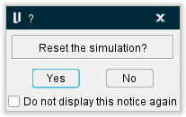
Yes — Continue with the reset of the model and rewind of the NC Program.
No — Do not reset the model or rewind the NC Program.
Do not display this notice again — When toggled on (checked), this confirmation window will no longer display when the Reset simulation control button is used.
Start At/Stop At Options window
Location:
Vericut main window > right click on the (Play / Start/Stop Options) icon
The features on the Start At / Stop At Options window enable you to specify conditions that control the starting, and stopping, of NC Program processing. Start At / Stop At options are also called Breakpoint options. When applicable, enter supporting "start at" text or values in the field next to the feature or select from the pull-down list. Text entered is not case sensitive.
The following picture shows the default Start At / Stop At settings when starting a new project file.
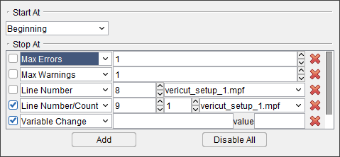
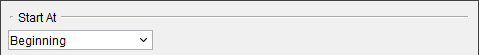
Start At — The Start At options enable you tp specify where you want the cutting simulation to start. Vericut fast forwards from the beginning of the NC program to the specified line/record while internally processing intermediate tool path records to store values for the current feed rate, spindle speed, coolant, tool description, and tool location. Options are:
- Beginning — Start NC program processing at the beginning of the first file.
- Line Number — Start NC program processing at the specified line number of selected NC program file.
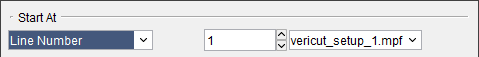
Highlight the number displayed in the text field and then enter the desired line number. Use the  to increment/decrement the displayed line number by 1.
Select the NC program from the pull-down list. The list will contain all of the NC programs and job subroutine files defined for the current job enabling you to select the NC program file.
- Line Number (Directly) — Start NC program processing at the specified line number without internally processing intermediate NC program records.
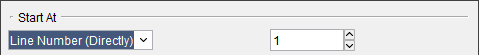
Highlight the number displayed in the text field and then enter the desired line number. Use the to increment/decrement the displayed line number by 1.
This line number only applies to the first NC program (or the first active NC program if Use Selected Files, in the Info tab > NC Program panel, is being used to select only specific NC program files from the list for Vericut processing).
- Text — Start NC program processing on the line that contains the specified text.
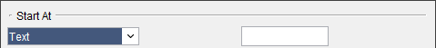
Enter the text that you want processing to start at in the text field.
- Tool ID — Start NC program processing when the specified tool is loaded.
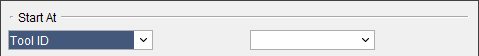
Select the desired Tool ID from the pull-down list.
Stop At — The Stop At options enable you to specify conditions for stopping NC program processing.
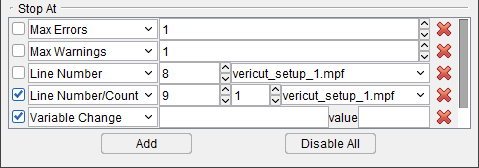
The following information is applicable to all “stop at” record types.
Use the  checkbox on the left side of the “stop at” condition record to make the record active (checked) or inactive (not checked).
Use the pull-down list to select the “stop at” condition record type. After selecting the “type”, supporting information fields will added to the record.
When applicable, enter supporting text or values in the field(s) provided, or use the pull-down list if one is provided, to select supporting data for each “stop at” condition record type. Text entered is not case sensitive.
Use the ![]() (Remove Breakpoint) button to remove the “stop at” condition record.
(Remove Breakpoint) button to remove the “stop at” condition record.
Use the  button to add a new “stop at” condition record. You can add multiple “stop at” condition records at any time, but only one “stop at” condition record of each type. The two exceptions are Text and Line Number type “stop at” condition records which can be added multiple times.
Use the  button to remove the check from all checkboxes on the left side of the “stop at” condition records at the same time to make all of the “stop at” condition records inactive.
If more “stop at” condition records than will fit in the window are added, a scroll bar is added to enable viewing the additional records.
Each of the “stop at” condition record types is described below.
Options are:
- Max Errors — Number of errors which, if detected, stops NC program processing.

Highlight the number displayed in the text field and then enter the desired number of errors that can occur before NC program processing is stopped. Use the to increment/decrement the displayed line number by 1.
- Collision — Stops NC program processing when a collision occurs.

This feature ONLY applies to the Machine Simulation collision checking, and ONLY to machine components other than the STOCK component. It does not apply to holder/stock and tool/fixture collision checks done from the material removal logic.
While simulating an NC block, Vericut stops in mid-motion at each collision point. Clicking Step continues simulation to the next collision point (or to the end of the motion if no more collisions exist).
- Tool Change — Stops NC program processing when a "tool change" record is encountered in the NC program.

- Text — Stops NC program processing on the line that contains the specified text.

Enter the “stop at” text in the field provided.
- Line Number — Stops NC program processing at the specified line number of the selected NC program file.

Highlight the number displayed in the text field and then enter the desired line number. Use the  to increment/decrement the displayed line number by 1.
Select the NC program from the pull-down list. The pull-down list contains all of the NC program and job subroutine files defined for the current job.
- Line Number/Count — When selected, creates a breakpoint on the current line being processed in the NC program, including the counted number of times visited, such as via branching/looping/macro.

- Each Motion Block — Stops NC program processing at the end of each motion block.

This option is intended to assist with the debugging of large complicated control subroutines. The concept is: skip over all the playing with variables, and just advance to the next motion.
“Motion” is being defined as any of the following (this may not be an all-inclusive list):
- An actual machine motion.
- A motion block, even if it doesn’t create an actual motion (G91 X0)
- A change of the local coordinate system (a change of offsets)
- A spindle being turned on or off
- A tool change
📝 NOTE: When motions occur within a within a machine or control subroutine in which we are stepping over (not stepping in), a stop will occur at the end of the project level block.
- End of each File — Stops NC program processing at the end of each NC program file.

- End of each Setup — Stops NC program processing at the end of each setup.

- Variable Change — Stops the NC Program processing whenever a variable changes.

Enter the "stop at" value in the field provided.
- Variable Set — Stops the NC Program processing whenever a new variable set occurs.

Enter the "stop at" value in the field provided.
- Program Stop — Stops NC program processing when a "program stop" record is encountered in the NC program. Examples of such records include: M0 (G-Code NC program files) or STOP.

- Optional Stop — Stop NC program processing when an "optional stop" record is encountered in the NC program. Examples of such records include: M1 (G-Code NC program files) or OPSTOP.

- Number of Lines — Stops NC program processing after the specified number of lines have been processed.

Highlight the number displayed in the text field and then enter the desired number of lines to be processed before NC program processing is stopped. Use the to increment/decrement the displayed line number by 1.
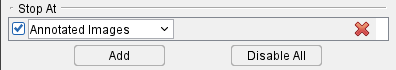
- Annotated Images — Stops NC program processing at any point which you have saved Annotated Images for further reference. See Annotated Images section of Vericut Help for more information on setting up Annotated Images.
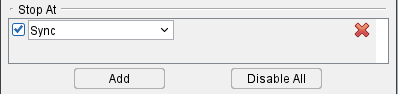
- Sync — Stops NC program processing when a sync command is given. The program will also output a message to the Vericut Logger indicating which sync was stopped at.
Subroutine Options
Location:
Vericut main window > right click on the (Step / Subroutine Options) icon
The Subroutine Options enable you to specify what you want Vericut to do when a subroutine is encountered during processing.
 Step Into Subroutine — When you come to a subroutine, step into the subroutine, and continue stepping.
 Step Over Subroutine — When you come to a subroutine, do not step into it, execute the subroutine, and continue stepping on the next line of the calling program.
 Step to End of Subroutine — If you are inside a subroutine, finish executing the current subroutine, and continue stepping on the next line of the calling routine.
💡 Tip: Position the cursor over the icon and a tip appears to remind you of each icon’s function.
Micro Step
The Micro Step feature enables “slow motion” processing. When extra intermediate points are generated during simulation it is possible to do “micro steps” by processing only one point at a time. Micro Step enables you to step to each intermediate point instead of from the start to the end of a single block like the Step animation control button does. When the distance is too short for generating intermediate points, Micro Step will behave exactly like the Step animation control button.
To use the Micro Step feature, move the Animation Speed Slider all the way to the left and then use the numeric key pad "+" key to step from intermediate point to intermediate point.
Animation Speed Slider
The Animation Speed Slider, located on the left end of the Animation Controls features, controls the speed at which Vericut animates material removal in workpiece views.
📝 NOTE: Animation Speed Slider cannot be set below 100% while Optimization is active.
The Animation Speed Slider will be displayed in one of three ways:
| Left (slowed down simulation) | Center (real time simulation) | Right (sped up simulation) |
|---|---|---|
 |
 |
 |
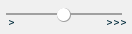
The slide bar at the center position represents an Animation Speed of 100%. This is the default position for the slider.
Slider to the left of the center position slows animation by adding intermediate tool display positions between motion start and end points as represented in Animation Speed percentages. The slide bar at the full left position represents an Animation Speed of 1%. Use Min. Motion Dist. and Max. Motion Dist. in Project Tree > Configure Setup menu: Motion tab to define the range for the Animation Speed Slider.
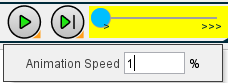
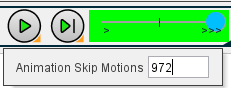
Slider to the right of center enables you to specify Animation Skip Motion value to group cuts together for even faster animation display. The Skip Motion value represents the number of animated tool motions to skip before updating the display. You can also specify the Skip Motion value in the Project Tree, on the Configure Setup menu: Motion tab.
Positioning the cursor over the slide bar displays an editable text field indicating the slider’s value at the current position as shown in the pictures that follow.
| Percentage | Skip Motions |
|---|---|
 |
 |