Main Window and Key Features
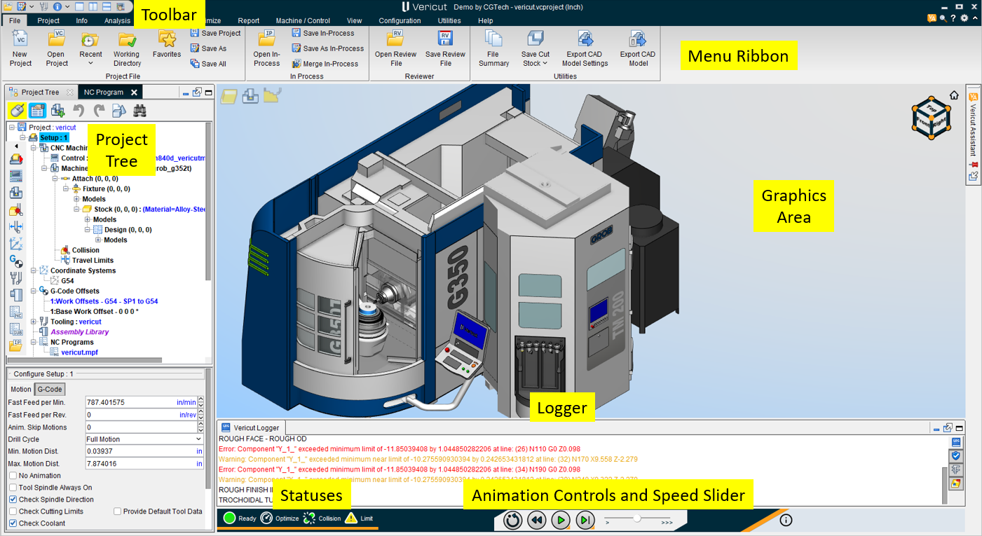
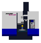
The Vericut main window is composed of distinct areas, each with different user interaction. The window header displays the last Project file loaded and the current session units (inch or millimeter). This window can be resized like most other window, via dragging the window header, sides or corners.
Tip: Press "F1" in any Vericut window to receive help on that window.
Main Window Buttons
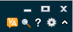
In the top right corner of the Main Window, there are 7 buttons that are standard across all Vericut products. They are as follows:
 (Minimize) — shrinks the main window down.
 (Full Screen) — expands the main window to fill the whole screen.
 (Close) — closes Vericut. Any files that were opened during the Vericut session, such as the Log file, Image file, etc. are automatically closed.
📝 NOTE: Be sure to save before closing the software.
![]() (Vericut Assistant) — opens the Vericut Assitant enabling you to query Vericut's AI copilot about Vericut's features.
(Vericut Assistant) — opens the Vericut Assitant enabling you to query Vericut's AI copilot about Vericut's features.
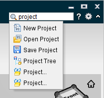
 (Feature Search) — clicking this option expands a search bar that can be used to find any feature in Vericut. Options related to entered search queries are displayed and can be clicked so that Vericut navigates directly to those features as shown below:
 (Help) — opens the Vericut Help.
![]() (Customize Ribbon) — opens the Customize Ribbon window.
(Customize Ribbon) — opens the Customize Ribbon window.
![]() /
/![]() (Minimize Ribbon/Display Ribbon) — alternately shrinks the ribbon menu or displays it again after being minimized. The minimized ribbon gives Vericut a cleaner look.
(Minimize Ribbon/Display Ribbon) — alternately shrinks the ribbon menu or displays it again after being minimized. The minimized ribbon gives Vericut a cleaner look.
The following are key features of the Main Window:
Menu Ribbon
The menu ribbon, located across the top of the Vericut window, provides easy access to Vericut functions. Each tab in the ribbon bar contains groups of related functions. Click with the left mouse button on any menu name to use the functions available in that menu. If an arrow appears below or to the right of a function in a menu, move the mouse over the arrow to expose a sub-menu of additional functions. Click on the function in the menu you want to use.
Vericut tab descriptions
In the following discussion the term "Vericut" will refer to Vericut, Vericut Drilling and Fastening, and Vericut Composite Simulation. Any exceptions will be noted within the topic.
The menus which provide access to all Vericut functions are listed below, followed by a brief description of what the menu's features do. The features contained in each menu's pull-down list will vary depending on the Vericut application that you are using.
In Vericut Help, select the desired menu and then select the desired feature for more information about each feature.
File tab — Features in this tab enable you to open and save the files most commonly used in Vericut, access converter products, control properties, export cut model data, and generate Vericut reports.
Project tab — Features in this tab enable you to specify information required for "job" setup including the display of the Project Tree. Features include selection of machines, controls, NC programs, tools, and processing options. Its features also enable the selection and setup of the output files created by Vericut during processing and creating customized reports.
Info tab — Features in this menu enable you to access session information, such as the files currently being used, machining status, machine offsets, and log files.
Analysis tab — Features in this tab are used to analyze and inspect the Vericut model.
X-Caliper tab — Features in this tab are used to measure and refine the Vericut model.
View tab — Features in this tab enable you to set up the number of views, orientation (angle and distance) for each view, and store or select commonly used views, and set up other Vericut display characteristics.
Optimize tab — Features in this tab provide access to Optimization and Vericut Force, the feed rate and spindle speed optimization tools that enable you to create "optimized" NC programs that enable you to cut parts in the least amount of time, compare your original NC program with the "optimized" NC program, and calculate time and money savings available from using the "optimized" NC program.
Report tab – Features in this tab enable you to create, view and edit reports and Log files.
Machine/Control tab – Features in this tab are used to optimize the control of your machines and variables.
Configuration tab — Features in this tab are used to build or configure NC machines and controls.
Utilities tab – Features in this tab are used to convert files into post processing systems, edit the NC Program, model Die Sinking Simulations, and connect to Heidenhain TNC.
Help tab — Features in this tab provide access to the Vericut online Help System, license information and current Vericut release information.
Customizing the Menu Ribbon
Location:
![]() (Ribbon) > Customize Ribbon window: Ribbon tab
(Ribbon) > Customize Ribbon window: Ribbon tab
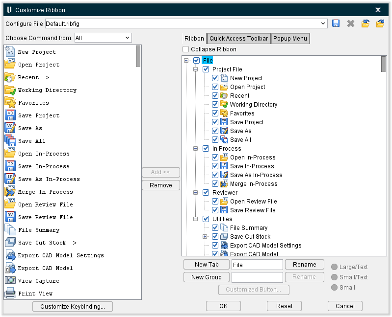
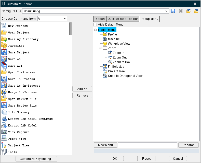
The Ribbon option opens the Customize Ribbon window enabling you to control when the Menu ribbon is displayed and the icons that it contains. Ribbon command buttons provide quick and easy access to the most commonly used Vericut functions/features. The Menu Ribbon can be closed, opened, or customized at any time. You choose which command buttons are displayed in the Menu ribbon and in what order.
Tip: Use the F1 key for Help on the View Toolbar window.
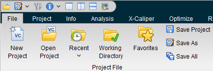
 (Minimize Ribbon) — When toggled off (unchecked), all of the icons in the command buttons in the Menu ribbon in the Vericut main window are displayed as shown in the picture below. By default, all command buttons are visible and displayed in the Menu Ribbon.

![]() Save Ribbon Configure File — The Save Ribbon Configure File option allows you to select different prefigured configurations for the Menu ribbon.
Save Ribbon Configure File — The Save Ribbon Configure File option allows you to select different prefigured configurations for the Menu ribbon.
![]() (Delete Selected Ribbon File) — Enables you to remove the selected Configure File completely. The Default Configure File cannot be deleted.
(Delete Selected Ribbon File) — Enables you to remove the selected Configure File completely. The Default Configure File cannot be deleted.
![]() Import Ribbon File — Enables you to select a saved Ribbon File configuration to be imported directly into the Configure File.
Import Ribbon File — Enables you to select a saved Ribbon File configuration to be imported directly into the Configure File.
 Export Ribbon File — Enables you to save a selected Ribbon File configuration outside of Vericut.
Choose Command from — Enables you to select which tabs or function related features the Available Command Buttons are displayed from. Available Command Buttons appear in the left hand column. The following are options available to choose from:
-
All — Displays all available command buttons that can be added to the Menu ribbon.
-
File — Displays all File tab command buttons that can be added to the Menu ribbon.
-
Project — Displays all Project tab command buttons that can be added to the Menu ribbon.
-
Info — Displays all Info tab command buttons that can be added to the Menu ribbon.
-
Analysis — Displays all Analysis tab command buttons that can be added to the Menu ribbon.
-
X-Caliper — Displays all X-Caliper tab command buttons that can be added to the Menu ribbon.
-
Report — Displays all Report tab command buttons that can be added to the Menu ribbon.
-
Machine/Control — Displays all Machine/Control tab command buttons that can be added to the Menu ribbon.
-
View — Displays all View tab command buttons that can be added to the Menu ribbon.
-
Configuration — Displays all Configuration tab command buttons that can be added to the Menu ribbon.
-
Utilities — Displays all Utilities tab command buttons that can be added to the Menu ribbon.
-
Help — Displays all Help tab command buttons that can be added to the Menu ribbon.
Customize Keybinding — opens the Customize Keybinding window, enabling you to set keyboard shortcuts for key features.
Available Command Buttons — The Available Command Buttons list contains all icons that are not currently displayed in the toolbar. By default, all icons are visible and displayed in the Menu ribbon.
Use the following arrow buttons to move icons from one list to the other.
 Use this arrow button to move one, or more, highlighted icons in the Available Command Buttons list to the Visible Command Buttons list.
 Use this arrow button to move one, or more, highlighted icons in the Visible Command Buttons list to the Available Command Buttons list.
Visible Command Buttons — The Visible Icons list is used to specify which icons are to be displayed in the Menu ribbon. Command buttons are added to the Menu ribbon in the order that they appear in the Visible Command Buttons list. The Visible Command Buttons list is displayed in the right hand column. Use the add and remove buttons to move icons to the Visible Command Buttons list.
💡 Tip: You can "drag" and "drop" one, or more, icons from one position in the Visible Command Buttons list to another position in the Visible Command Buttons list. Left-click on a single icon in the Visible Command Buttons list so that it becomes highlighted, and then while keeping the mouse button depressed, drag the icon to the desired position in the Visible Command Buttons list and release the mouse button. The position of the cursor, when you release the mouse button, will determine where the icon is "dropped".
You can also use the above the "drag" and "drop" procedure to move icons from one position to another in the Available Command Buttons list.
Use one of the procedures described below to select, and highlight, multiple icons to be "dragged" and "dropped" from one position in the list to another.
New Tab — creates a new tab to place features in. The tab can named anything using the adjacent text field.
New Group — creates a new group within a tab to place features in. The group can be named anything using the adjacent text field.
Rename — can be used to rename any tab or group. Use the adjoining text field to write a new name and then select Rename.
Text size — use this group of buttons to control the size of the text.
Customized Button — this opens the Customized Button window, enabling you to specify title, icons and executable files for the button or group of your choice. If icon files are not specified, the default icon is used.
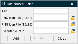
Features on the Customized Button... window include:
-
Text — this field is used to modify the title of a button or group.
-
PNG Icon File (32x32) — can be used to select a new image for a button or group.
-
PNG Icon File (16x16) — can be used to select a new image for a button or group.
-
Executable Path — can be used to select a new executable path. This enables you to connect Vericut to an outside application.
-
Add — adds the changed fields to the selected button or group.
-
Modify — modifies the changed fields for the selected button or group.
-
Close — closes the window without implementing any changes.
-
OK — Click OK, to accept your changes and close the Customize Ribbon window.
-
Reset — Click Reset to revert the Vericut ribbon back to the default settings.
-
Cancel — Close the Customize Ribbon window without accepting changes.
Both the Available Icons list and the Visible Icons list enable you to select one, or more, icons at the same time. To select multiple icons in these lists, try these techniques:
Select multiple icons in sequence — Click the first icon/name in the sequence so that it becomes highlighted, then press and hold the
Select additional individual icons — Click the first icon/name so that it becomes highlighted, then press and hold the
With either method, selecting an icon/name a second time, while holding down the
Customize Keybinding
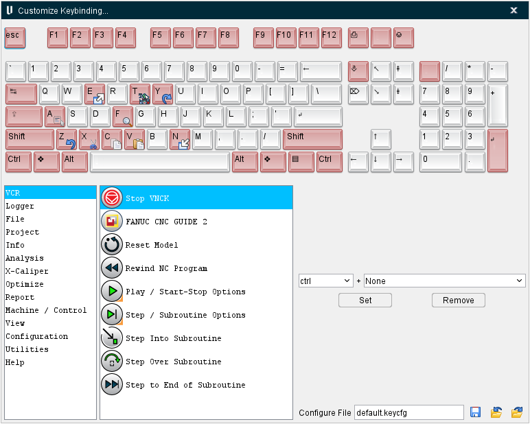
The Customize Keybinding window enables you to quickly set and remove keyboard shortcuts for key Vericut functions so that these functions can be accessed quickly in the future. The top of the window displays a visual representation of the keyboard along with image of which function have been bound to which keys.
To set up a key shortcut, select a major function group from the left hand column (options for this column include the Animation Controls, the Logger, and every major tab) and then select the desired related function from the right hand column. Use the pulldown menus to select the key combination that will be used to access this feature (example: File > New Project could be set to \<ctrl> + \<spacebar>). Once the desired setup has been configured, click the Set button to save the configuration. The Remove button can be used to clear the specific configuration. The keyboard image at the top of the window updates to display keybound functions as they are set.
Configure File — use this field to name the configuration file.
Save Keybind Configure File — use to save the configuration file.
Import Keybind Configure File — use to import a previously saved configuration file through a file selection window.
Export Keybind Configure File — use to export the current configuration file.
Quick Access Toolbar
Vericut's Quick Access Toolbar provides quick and easy access to the most commonly-used functions/features.

To see what is associated with a Toolbar icon, simply position the cursor over the icon and a tip appears.
To hide the Toolbar:
Right click on the Toolbar and select Hide Quick Access Toolbar from the menu that displays.
OR
Select ![]() (Ribbon) to display the Customize Ribbon window.
(Ribbon) to display the Customize Ribbon window.
Select Quick Access Toolbar then select Hide Quick Access Toolbar then click OK.
You can also customize the Toolbar to suit your needs. See Customizing the Quick Access Toolbar section of Vericut Help below for information on individual icons and customizing the Toolbar.
💡 Tip: Use the F1 key for Help on the Toolbar. When the toolbar is undocked, click anywhere in the Toolbar to give it focus, then press the F1 key. When docked, you can also get to the Help if you click on one of the "mode" icons (Translucent, Dynamic Rotation, Pan, etc.) to give the Toolbar focus, then F1.
Customizing the Quick Access Toolbar
Location:
![]() (Ribbon) > Customize Ribbon window: Quick Access Toolbar tab
(Ribbon) > Customize Ribbon window: Quick Access Toolbar tab
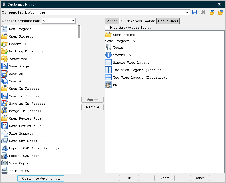
The Ribbon option opens the Customize Ribbon window enabling you to control when the Toolbar is displayed and the icons that it contains. Toolbar icons provide quick and easy access to the most commonly used Vericut functions/features. The Toolbar can be closed, opened, or customized at any time. You choose which icons are displayed in the Toolbar and in what order.
Tip: Use the F1 key for Help on the View Toolbar window.
 (Hide Quick Access Toolbar) — When toggled off (slider to the left), selecting OK displays all of the icons in the Visible Icons list in the Toolbar in the Vericut main window as shown in the picture below. By default, all icons are visible and displayed in the Toolbar.
The remainder of the features on this tab and available icons to add/remove are identical to those described in Customizing the Menu Ribbon
Popup Menu
Vericut's Popup Menu provides quick and easy access to the most commonly-used functions/features when you right-mouse click within the graphics window.
Customizing the Popup Menu
Location:
![]() (Ribbon) > Customize Ribbon window: Popup Menu tab
(Ribbon) > Customize Ribbon window: Popup Menu tab
The Ribbon option opens the Customize Ribbon window enabling you to control when the Popup Menu is displayed and the icons that it contains. Popup Menu icons provide quick and easy access to the most commonly used Vericut functions/features.
The remainder of the features on this tab and available icons to add/remove are identical to those described in Customizing the Menu Ribbon
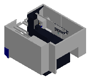
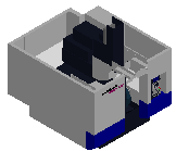
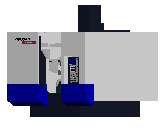
Graphics Area
The graphics area is where solid models of the workpiece, fixtures, etc. are displayed, and where the simulation takes place. By default, two views are displayed: a Workpiece view and a Machine Cut/Stock view. Using View tab > Layout group you can add additional views displaying the workpiece or NC machine (if a machine is defined) . All views are contained within the Vericut main window.
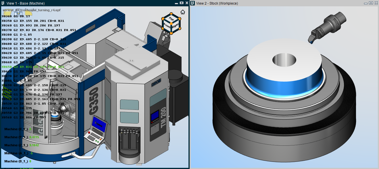
Many other Vericut functions enable user interactions in this area, including: picking models or surfaces to be measured, determining NC program records responsible for specific cuts, and more.
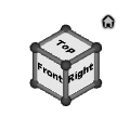
Vericut View Port Controls (View Cube)
The Vericut View Port controls, or View Cube, tracks the rotation of the view that is currently active in the Vericut Graphics area. Pan and Zoom have no effect on the cube. When you rotate the view in the graphics area, the cube rotates to the same orientation. Conversely, if you rotate the cube in the View Port control area, view in the graphics area will rotate to the same orientation.
The entire cube is a combination 26 buttons that are triggered by a left click. 12 edge views represented by the cylinders on the edges of the cube, 8 isometric views represented by 8 spheres at the corners of the cube and 6 standard views represented by the labeled sides of the cube. See the picture below.

Other features in the View Port Controls area enable you to specify view related characteristics. The  (Home) icon in the upper left corner of the View Port Controls area enable you to specify a view to represent a “home” view orientation that you can return to with a single mouse pick. It also enables you to specify the planar view that you want to represent the “Front” view.
Each of these features is shown in the picture above and is described in detail in the sections that follow.
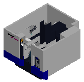
Standard View Selection
A standard view is considered to be a planer view of the Front, Back, Top, Bottom, Left, or Right. To change to a standard view, click on any visible plane on the cube. At that time the active View and the cube will rotate to that position and orientation so that the label is positioned parallel to the screen. The view will also be automatically centered and “Fit” in the active viewport.
To view the five non-visible sides, click on any standard view so that the arrows shown in the picture below become visible and then use them to rotate to the desired standard view.
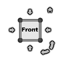
Click on the right facing arrow to rotate the cube and the view to the right. Click on the left facing arrow to rotate the cube and the view to the left. Similarly, click on the down facing arrow to rotate the cube and the view down. Click on the up facing arrow to rotate the cube and the view up.
Click on the left facing curved arrow in the upper right corner to rotate the current view counterclockwise. Click on the right facing curved arrow in the upper right corner to rotate the current view clockwise.
By default, each time that you click on an arrow, the cube and the view will rotate 90 degrees. You have the ability to change the rotational increment. This will be described in the Changing the Rotational Increment section.
Continue clicking on the arrows until you get to the desired standard view on the cube.
Non-standard View Selection
Non-standard views consist of Isometric views and Edge views. Isometric views are selected using the spherical corners of the cube. Edge views are selected using the cylindrical edges of the cube as shown in the picture below.
Isometric View Examples
In the following examples, the X indicates the pick location in the current position to get the Cube/View to the next rotated orientation. The  indicates the pick location at the end of the rotation.
| Cube | View | |
|---|---|---|
| Cube Initial | |
 |
| 1st Rotation | 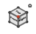 |
 |
| 2nd Rotation | 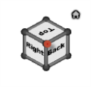 |
 |
| 3rd Rotation | 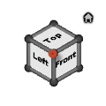 |
 |
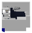
Edge View Examples
In the following examples, the X indicates the pick location in the current position to get the Cube/View to the next rotated orientation. The indicates the pick location at the end of the rotation.
| Cube | View | |
|---|---|---|
| Cube Initial | |
|
| 1st Rotation | 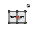 |
 |
| 2nd Rotation | 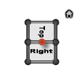 |
 |
| 3rd Rotation | 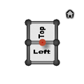 |
 |
Specifying a “Home” and a “Front” View
The (Home) icon enables you to specify the view that you want to be the “home” view. The “home” view should be the view that you most frequently display. Specifying a “home” view enables you to return to that view with a single mouse click.
The (Home) icon also enables you to specify the view that you want to represent the “Front” view as described in the Standard View Selection section.
Right-click on the (Home) icon to display the following menu.
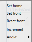
Set home — This feature enables you to set the current view as the “home” view. Once specified, this view is displayed whenever you left-click on the (Home) icon. Do the following to specify your “home” view.
- Orient the current view to the view that you want to use as your “home” view.
- Right-click on the (Home) icon to display the menu above.
- Left-click on the Set home option in the menu to designate that the current view is to be used for the “home” view.
Set front — This feature enables you to set the current view as the “Front” view. Once specified, this view is displayed whenever you Left-click on the “Front” face of the cube. Do the following to specify your “Front” view.
- Orient the current view to the view that you want to represent the “Front” view.
- Right-click on the (Home) icon to display the menu above.
- Left-click on the Set front option in the menu to designate that the current view is to be used for the “Front” view.
Reset front — Selecting the Reset front option in the menu caused the Cube/View to align itself with the Machine Origin coordinate system.
Changing the Rotational Increment
Right clicking any part of the View Cube opens a menu which enables you to specify the rotational increment that you want to use when rotating the Cube/View.
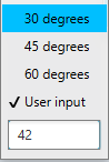
Click on the Angle option to display the following menu.
-
30 degrees — When selected (checked) the cube and the view will rotate 30 degrees each time you click on an arrow in the “custom” rotation display in the View Port Controls area.
-
45 degrees — When selected (checked) the cube and the view will rotate 45 degrees each time you click on an arrow in the “custom” rotation display in the View Port Controls area.
-
60 degrees — When selected (checked) the cube and the view will rotate 60 degrees each time you click on an arrow in the “custom” rotation display in the View Port Controls area.
-
User input — Left-click on this feature and then use the text box immediately below it to manually enter your desired rotation angle.
The specified angle will be used each time you click on an arrow in the “custom” rotation display in the View Port Controls area.
Select the Increment option to display the “custom” rotation display in the View Port Controls area.
You can return to “default” mode by opening the right mouse button menu again and selecting increment again.
Capture, Edit, Activate, and Remove Views
These features are controlled in the View tab > Saved Layout group. Consult that section of the Vericut Help for additional information.
Mouse Hover Info
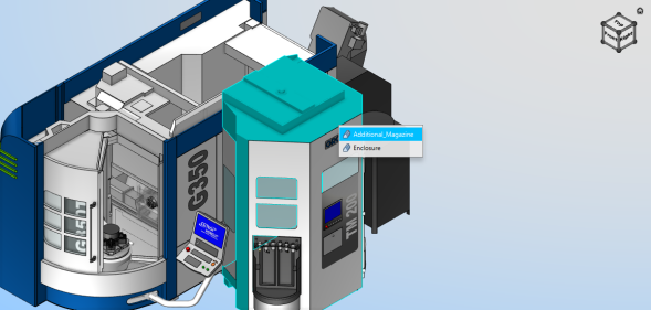
You can hover over it with the mouse until a popup generates. Selecting one of the listed components in the hover popup will focus on the selected model and remove extraneous info. To go back to the original view, hit the <ESC> key.
Mouse Pick Indicator
The windows that allow selecting geometry in the graphics area have a "Mouse Pick" indicator icon  which enables you to designate which window picks in the graphics are to be applied to if more than one of these windows is open. Click on the icon to toggle the feature On/Off. If you toggle the “Mouse Pick” indicator “on” in a window, Vericut automatically toggles "off" the “Mouse Pick” indicator in all other open windows.
When toggled "on", the icon is displayed in the Mouse Pick Highlight Color specified in the Configuration tab > Preferences window.
Graphics Area Right Mouse Button (RMB) Shortcut Menus
Right Mouse Button Shortcut Menus, or RMB menus, provide easy access to most frequently used features.
Right-click in a view to display Shortcuts menu, as shown in the illustration below, enabling you to modify its attributes, such as: view type, standard modeling views, background, etc. Use dynamic and static view options on the Tool Bar to rotate, zoom, or fit the model.
Sample Vericut Right Mouse Button menu
The options will vary depending on the type of view.
Graphics Area RMB Menu Locations
The following sections describe the Right Mouse Button Menu options that are available in the various view types in Vericut.
Radial Menu
Right-click in any view to display the Radial Menu, a customizable menu that shows commonly used Vericut features. These features can be rearranged or altered in the Popup Menu tab of the Customize Ribbon window.
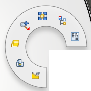
Default Radial Menu
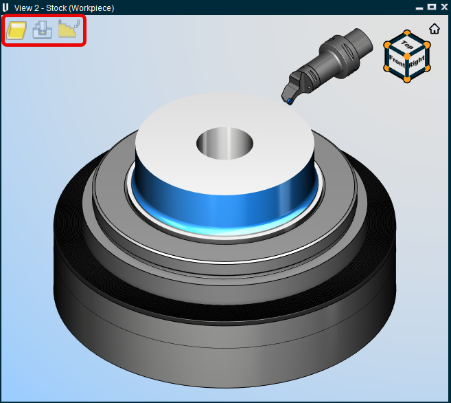
Profile — Sets the currently active Graphics Area view to the Profile view. In profile view, an isometric rendering of the stock is displayed.
Machine — Sets the currently active Graphics Area view to the Machine view. In machine view, as the name implies, the machine will be visible.
Workpiece View — Sets the currently active Graphics Area view to the Workpiece view. In workpiece view, a faithful rendering of the stock is shown.
You can also quickly toggle between the above options by using the icons located in the upper left hand corner of the currently active view (see below).
Zoom —
-
Zoom In — zooms in.
-
Zoom Out — zooms out.
-
Zoom to Box — allows you to zoom into a selected space.
Fit selected — "Fits" the objects in the view. (ref. View Orient window).
Project Tree — Opens the Project Tree panel.
Snap to Orthogonal View — Snaps the current view to the closest orthogonal view. (ref. View Orient window).
Machine, Profile and Workpiece View
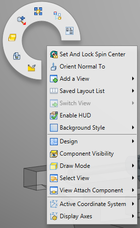
Right-click in any view to display a menu with the following features:
Set and Lock Spin Center — Defines a spin center wherever you right-clicked.
Orient Normal To — Orients to the normal of a feature. See View Orient window section for more info.
Add a View — Use to add a view of the specified type. You can add as many views as desired.
Saved Layout List — Contains a list of saved views that can be quickly navigated to.
Switch View — Once multiple views are saved, you can use this feature to quickly switch to an additional view.
Enable HUD — Turns on the HUD.
Background Style — Use to specify the background style for the view. (ref. View Attributes window, in the View tab section of Vericut Help).
Enclosure — Use to specify whether machine enclosures are visible or active or neither in the graphics area.
Focus on Selected Models — Hides every model except the selected model. You can undo the focus by hitting the Esc key.
Component Visibility — Use to make the selected component visible (checked), or not visible (not checked), in Workpiece views in the Vericut graphics area. A check indicates that the component is visible.
If the component list contains more than 32 items, Vericut will automatically break up the list into sub-lists. Each sub-list will be identified by the first, and last, component in the list.
The View Components option displays the View Components window which enables you to toggle on (checked)/toggle off (not checked) the visibility of multiple components at the same time.
📝 NOTES:
-
Only Components that have models associated with them in the Project Tree are displayed in the Component Visibility list.
-
Tool Components do not appear in the Component Visibility list. See Holder Visibility and Cutter Visibility in the Project Tree section of Vericut Help for information on controlling tool component visibility
Draw Mode — Use to specify how machine components are displayed. (ref. View Attributes window, in the View tab section of Vericut Help).
Select View — Orients the objects in the view to the selected view. The Select View feature list will contain all available standard and custom views.
View Attach Component — Attaches the view point and line of sight for a view to the selected component. (ref. View Attributes window, in the View tab section of Vericut Help).
Active Coordinate System — Use to designate the "active" coordinate system. (ref. Active Coordinate System, in the Project Tree section of Vericut Help.
Display Axes — Use to control when various axes and coordinate systems are displayed. A check next to any of the Display Axes features indicates that the feature is toggled "On". (ref. View Axes window, in the View tab section of Vericut Help)
Component Visibility window
Location:
Graphics Area right mouse button menus: Component Visibility option
The Component Visibility window enables you to toggle on (checked)/toggle off (not checked) the visibility of multiple components at the same time.
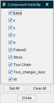
Component List — the component list contains all components in the particular view.
Set All — toggles on (checked) the visibility of all components in the Component List.
Clear All — toggles off (unchecked) the visibility of all components in the Component List.
Close — closes the View Components window.
Dynamic Zoom, Pan, and Rotate
The Dynamic Zoom, Pan and Rotate features enable you to manipulate the displayed image of a view using a single mouse button.
| Motion | Mouse Control | Description |
|---|---|---|
| Rotate |  |
Click with the left mouse button in a view and drag the mouse to rotate the display. |
| Pan |  |
Click with the right mouse button in a view and drag the mouse to rotate the display. |
| Zoom |  |
Rotate the thumb wheel while the cursor is in a view to zoom in or out on the display. Move the wheel toward you to make the displayed image larger. Move the wheel away from you to make the displayed image smaller. |
| Zoom to Box |  |
Press the thumb wheel down in a view and drag the mouse to define the box to zoom to. Release the thumb wheel to start the zoom. You can also click the thumbwheel to define the first corner of the box, and then move the mouse to the position defining the other corner of the box and click again. |
📝 NOTES:
-
Dynamic Controls (Configuration tab > Preferences window: Display tab) must be set to Vericut.
-
The Shift key, Ctrl key, and mouse button combinations used in pre-V6.1 for view manipulation is still available.
- The Shift key, Ctrl key, and Arrow key combinations are no longer available.
- In AUTO-DIFF, when using Compare By Region, the dynamic rotate with the left button is suspended as long as the Drag Region button is active.
You can also rotate or pan views by using your keyboards arrow keys along with the following modifiers:
-
No modifiers: incremental rotation of view (15 degree increments).
-
Arrows + \<Ctrl> key: centered zoom of view
- Arrows + \<Shift> key: incremental pan of view
These choices match the behavior used by the Vericut mouse preset and they work on all views (Vericut main desktop, Tool Manager, little tool view in project tree, etc.).
Right Mouse Button (RMB) Shortcut Menus
Many Vericut windows have Right Mouse Button (RMB) shortcut menus. When a window has an RMB menu, right-clicking within that window will generate a menu that contains features specific to that window. Descriptions and explanations of each specific RMB menu will appear in the section of Vericut Help that describes the window the RMB is associated with.