Models Branch
Right-click on a Models Branch in the Project Tree panel to display the following feature:
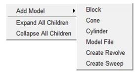
Add Model — The Add Model pull-down list contains the model types that can be added to an Attach Component. Select from the listed model types (ref. Model Type in the Configure Component menu, Common Features section for complete information on each model type).
Expand All Children — Expands all branches of a Models branch.
Collapse All Children — Collapses all branches of a Models branch.
If the Configure icon is toggled “on”, the Configure Models Branch menu displays at the bottom of the Project Tree.
Model
Right-click on a Model in the Project Tree panel to display the following menu:
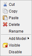
Cut — Cuts the highlighted model from the Project Tree and puts it in the paste buffer.
Copy — Copies the highlighted model from the Project Tree to the paste buffer.
Paste — Adds the contents of the paste buffer after the highlighted model in the Project Tree.
Delete — Deletes the highlighted model from the Project Tree.
Rename — Use to rename the highlighted model.
Add Model — The Add Model pull-down list contains the model types that can be added to an Attach Component. Select from the listed model types (ref. Model Type in the Configure Component menu, Common Features section for complete information on each model type).
Visible — Use to make the highlighted model visible, or not, visible in the Vericut graphics area. The Visible icon will indicate the visibility status of the model. ![]() indicates "visible",
indicates "visible", ![]() indicates "not visible". Click on Visible to toggle between the two modes. In the Project Tree, any model in the "not visible" state will be displayed in gray instead if a color. This button can also be used to make initial stock models visible after cut stock is created.
indicates "not visible". Click on Visible to toggle between the two modes. In the Project Tree, any model in the "not visible" state will be displayed in gray instead if a color. This button can also be used to make initial stock models visible after cut stock is created.
If the Configure icon is toggled “on”, the Configure Model menu displays at the bottom of the Project Tree.
Disable/Enable — Use to make the selected model active or inactive in the machining process.
Cut Stock
Right-click on a Cut Stock in the Project Tree panel to display the following menu:
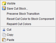
Visible — Use this feature to toggle visibility on or off as needed.
Save Cut Stock — The Save Cut Stock option opens the Save Cut Stock file selection window enabling you to save the selected Cut Stock model as a Vericut Solid file (.vct). This option is only active after a Cut Stock model has been created by Vericut. The default file extension is .vct. (ref. Save Cut Stock > Vericut Solid in the File tab section of Vericut Help for additional information)
Preserve Stock Transition — Use to create the coordinate systems required for transitioning the cut stock(s) from one setup position to another. Preserve Stock Transition can be used to create the coordinate systems for each Stock component. Preserve Stock Transition is only active when a stock component model is selected.
When Preserve Stock Transition is pressed, two coordinate systems named "Previous Setup name:Current Setup name:Active Stock component name" are created and added. Previous Setup name, Current Setup name and Active Stock component name are replaced by the actual names of these entities used in the project file, for example "Rough:Finish:Stock1". One CSYS is added to the current setup, attached to the Stock Component parent of the selected model. It is created with Use for Cut Stock Transition toggled "On" (see the Coordinate System window, Define section), designating it as a coordinate system used for transitioning the cut stock from one setup position to another. The other CSYS is added to the first setup in the project, and is located at the origin of the stock component whose name matches current setup stock component. The following illustrates how to use Preserve Stock Transition:
-
Configure Setup #1.
-
Simulate.
- Configure Setup #2.
- Move cut stock into position using cut features and assembly modeling to position the cut stock.
- Press Preserve Stock Transition.
- Simulate.
- Configure Setup #3.
- Move cut stock into position.
- Press Preserve Stock Transition.
- Simulate.
- and so on ...
Reset Cut Color to Stock Component — Use this option to reset each cut stock to the original color of its parent component.
Repaint Cut Colors — Use this option to apply the cut color list to the cut stock model and database.
Cut — Cuts the highlighted model from the Project Tree and puts it in the paste buffer.
Copy — Copies the highlighted model from the Project Tree to the paste buffer.
Paste — Adds the contents of the paste buffer after the highlighted model in the Project Tree.
Save or Load a Vericut Solid (.vct file)
The Vericut "Cut Stock" model can be saved as a Vericut Solid file, then later loaded as a Stock, Fixture or Design component model.
To save a "Cut Stock" model as a Vericut Solid file:
From the Vericut menu ribbon
-
In the Vericut Menu ribbon, or click File tab > Save Cut Stock > Vericut Solid > stock, where stock is the cut stock to be saved, to display the Save Cut Stock file selection window.
-
In the Save Cut Stock file selection window that displays, enter a /path/filename for the Vericut Solid file to be saved.
- Toggle "Save with Features" On (checked), or Off, depending on whether you want geometry, history database and cut database data saved in the Vericut solid file, or just geometry data. Then select Save in the file selection window to save the Vericut solid file.
You can load saved Vericut Solid files as described below.
From the Project Tree
-
Click
 (Project Tree) on the Toolbar, or click Project tab > Project Tree in the Vericut main menu ribbon to display the Project Tree panel.
 -
In the Project Tree panel, right-click on the "Cut Stock" model and then select Save Cut Stock in the pull-down menu to display the Save Cut Stock file selection window. (If there is no "Cut Stock" model in the Project Tree, process the NC program using
 (Play / Start-Stop Options).
 - In the Component Tree main menu click on File > Save Cut Stock.
- In the Save Cut Stock file selection window, enter a /path/filename for the Vericut Solid file to be saved.
- Toggle "Save with Features" On (checked), or Off, depending on whether you want geometry, history database and cut database data saved in the Vericut solid file, or just geometry data. Then select Save in the file selection window to save the Vericut solid file.
You can load saved Vericut Solid files as described below.
To load a Vericut Solid file:
-
Click
(Project Tree) on the Toolbar, or click Project tab > Project Tree in the Vericut main menu ribbon to display the Project Tree panel. -
In the Project Tree panel, use one if the following methods to load a Vericut solid file:
In the Project Tree, right-click on the component that you want to add the Vericut solid file to and then select Add Model > Model File in the pull-down menu, to display the Open file selection window. Use the file selection window to specify the /path/filename of the Vericut solid file (.vct) that you want to load.
In the Project Tree panel, click on the component that you want to add the Vericut solid file to so that it becomes highlighted.
In the Configure Component menu at the bottom of the Project Tree panel, select Model File from the Add Model pull-down list to display the Open file selection window.
Use the file selection window to specify the /path/filename of the Vericut solid file (.vct) that you want to load.
Vericut adds the model to the component.
See the Cut Stock and Configure Component menu sections of Vericut Help.
Also see Vericut Solid in the File tab section of Vericut Help.