Component Types
Features related to each Component Type are described below. Component Types will be listed in the order they appear in the Component Type pulldown menu of the Configure Component menu, Component tab.
Common features
Many aspects of the Configure Component menu, Component tab stay the same for most Component Types. Below are descriptions of those features:
Component Type — Enables you to edit the component's "Type" setting which determines the component's function in the simulation. Select the desired "Type" from the pull-down list. A full list of Component Types can be seen on the Configure Component menu, Component tab section of Vericut Help.
Visibility — Controls the views in which the component is visible. The following is a list of Visibility options:
-
Blank — Component is blanked from all views and cannot be seen.
-
Workpiece View — Component is seen in the workpiece view.
-
Machine View — Component is seen in the machine view.
-
Both Views — Component is seen in both the workpiece and machine views.
📝 NOTE: The Visibility feature is not available for Tool Components. See Holder Visibility and Cutter Visibility section of Vericut Help for information on controlling tool component visibility.
Enabled — Toggle on (checked), to make this component active in the Project Tree.
Apply to Sub-Components — Clicking this button applies the Translucent and Enabled conditions to all items under this component in the Project Tree.
Appearance — Use this feature to specify a color for the component. The right side of the  (Color Palette) icon shows the current color for the component. To change the color for the component, click on the (Color Palette) icon to display the color palette window shown below.
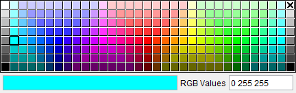
Click on a color in the color palette window, to specify the color for the component. The color palette will close and the right side of the  (Color Palette) icon in the Configure Component menu: Component tab will update to reflect the selected color.
To close the color palette window without changing the color, click on the  in the upper right corner of the color palette.
Use Default Appearance — Use this option to revert Color choices to the default.
Save to Appearance Defaults — Use this option to save current Color choices as a default.
Translucent — Toggle on (checked) to ensure component models are displayed as translucent (can be seen through).
Export Assembly — Export Assembly copies the selected component and its children to an Assembly and saves it to an assembly library file.
-
Existing library… — Opens a file selection box to select which file to add the Assembly to and saves the file.
-
New library… — Opens a file selection box to create a new library file and saves the Assembly to it. If the name of the library file already exists, it will be replaced.
Append Component — Use this pulldown menu to select an additional component to add as a child of this component.
Add Model — Use this pulldown menu to select a model to add as a child of this component.
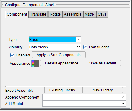
Component Types: Base, Deflector, Design Points, Electrode, Guide, and Other
All features on the Component tab for these Component Types are described in the Common Features section above.
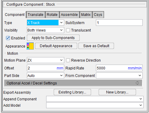
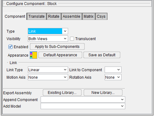
Component Type: Stock
The following picture shows the Component tab that applies directly to the following Component Type: Stock.
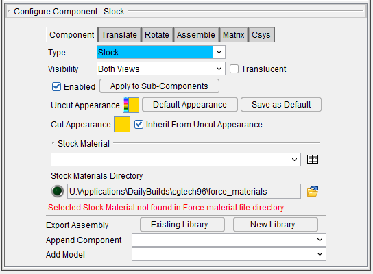
Stock Material — This field lists the type of material that is used for stock in this project. Stock Material can be changed through the Stock Material Catalog which can be opened by clicking the Choose From Catalog button. This opens the Stock Material Catalog window, enabling you to select Stock Materials for your project from a pre-generated list of options.
Stock Materials Directory — This field lists the filepath to reference Stock Materials. Use the browse icon ( ) to open the file selection folder to select your pathway. A green light indicates that the pathway is good.
Stock Material Catalog — This window enables you to search through all available material options for your stock materials. Use the ISO Group or Filter option at the top to find the Stock Material Name, Tool Material, or Tool Edge Type you are looking for. You can toggle between View Stock Materials and View Stock and Tool Info to see different levels of information about each material. Once you have highlighted your material, click Save As Optimize Stock Material to implement your selection.

📝 NOTE: The Stock Material options only appear when in the Configure Component: Stock menu.
The remaining features on the Component tab for Stock components are described in the Common Features section above.
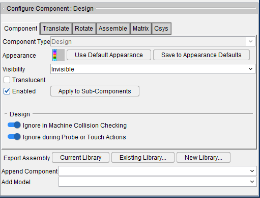
Component Type: Design
The following picture shows the Component tab that applies to Design components.
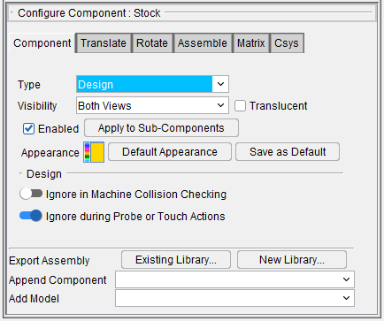
Ignore in Machine Collision Checking — When toggled on (checked), controls when the Design component is ignored for collision checking against machine components, even when the Design component is present in the collision table. Turn this option OFF to enable collisions between Design and machine components. This feature is on by default.
Ignore during Probe or Touch Actions — When toggled on (checked), controls when the Design component is ignored by probing (via Probe macro) or touching (via Touch macro). Turn this option OFF to enable the Design component to be sensitive to probing/touching actions. This feature is on by default.
The remaining features on the Component tab for Design components are described in the Common Features section above.
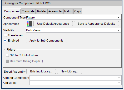
Component Type: Fixture
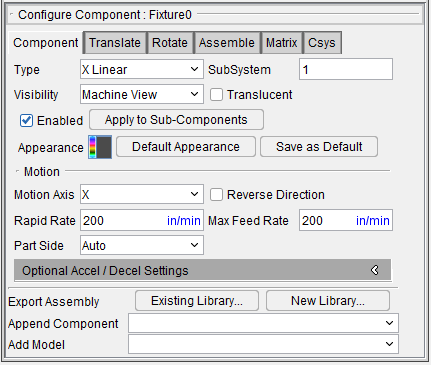
The following picture shows the Component tab that applies to Fixture components.
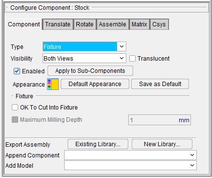
OK To Cut Into Fixture — Toggle this feature on (checked) to specify when it is acceptable to cut into a fixture. This feature is only available when Component Type is Fixture.
Maximum Milling Depth — After OK To Cut Into Fixture is on, this feature can be toggled on (checked) to specify the maximum depth, as measured along the tool axis, that a mill or tap cutter can cut into the fixture. A value of 0 will result in a "Maximum Milling Depth must be positive" message in the Logger and if you press Play, the feature will toggle itself off. This feature is only applicable to milling or tapping cuts. It is ignored for turning cuts.
The OK To Cut Into Fixture and Maximum Milling Depth features work together in the following ways:
Milling and Tapping Cuts
When OK to Cut Into Fixture is toggled "On" but Maximum Milling Depth checkbox is toggled "Off" (not checked), all cutter/fixture collisions are ignored, no matter what value Maximum Milling Depth is set to.
When both OK to Cut Fixture and Maximum Milling Depth are toggled "On" (checked), cutter/fixture collisions are only reported if the collision depth is greater than the specified Maximum Milling Depth value, as measured along the tool axis.
Turning Cuts
For turning cuts, cutter/fixture collisions are not reported regardless of collision depth.
When OK To Cut Into Fixture is toggled "Off" (not checked), any cutter/fixture contact produces an error.
📝 NOTES:
-
The OK To Cut Into Fixture feature is only relevant for valid milling, tapping, or turning cuts. For instance, if a milling cutter collides with the fixture while in an invalid spindle state, this option will be ignored and the collision will be reported as usual.
-
The behavior described above applies only for cutter/fixture collisions. Holder collisions and other machine component collisions are not affected by the above check box states.
- Both settings are saved in the fixture component.
- Depth is measured along the tool axis.
The remaining features on the Component tab for Fixture components are described in the Common Features section above.
Component Type: Tool
The following picture shows the Component tab that applies to Tool components.
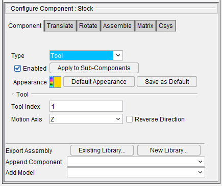
Tool Index — The Tool Index feature enables you to specify the index number for a Tool component. When defining machines with multiple tool load positions, such as a multi-spindle mill or a turret lathe machine with tools loaded in a turret, the Tool Index feature enables you to define additional Tool components with different index numbers for each tool load position. Values entered are integer numbers. Use the "ActiveTool" macros to activate each Tool component for tool changes. For example, call "ActiveTool2" to activate the Tool component with Tool Index=2, and so on.
The Tool features (Motion Axis and Reverse Direction) provide the same functionality described below for Motion Axes components.
📝 NOTE: A Tool component's SubsystemID is inherited from its parent motion component and cannot be configured.
The remaining features on the Component tab for Tool components are described in the Common Features section above.
Component Type: Tool Chain
The following picture shows the Component tab that applies to Tool Chain components. Notice that there is also an additional tab: Tool Chain. Both of these tabs are described below.
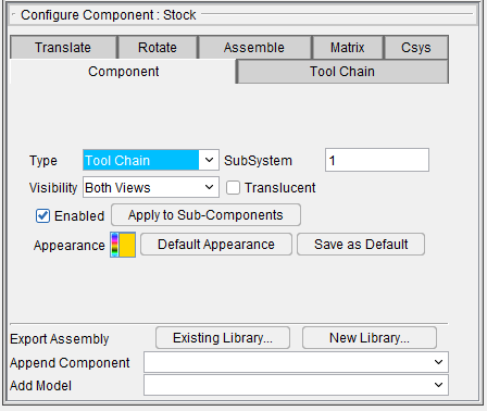
SubSystem — Subsystem which commands a linear or rotary motion type component to move. Any alpha-numeric sub-system name can be entered (may include spaces) and is always considered as text. Enter "*" (without the quotes) for motion axes included in all machine subsystems. Subsystems are used in machines with multiple motion components that are commanded to move via the same G-Code word, for example "X". By default, a machine uses one subsystem for all motion components, assuming they are commanded to move via unique G-Code words.
When multiple motion components are driven by the same G-Code word, such as can occur in 4-axis lathes or mills with multiple independently controlled heads, define different subsystems to control which component moves when the motion command is processed. Then, configure the control so that other codes in the tool path activate the appropriate subsystem for movement. A full set of tables are available to support each machine subsystem.
Tool Chain tab — Features on the Tool Chain tab are used to define tool chain characteristics.
The remaining features on the Component tab for Tool Chain components are described in the Common Features section above.
Tool Chain tab
The features on the Tool Chain tab are used to define tool chain characteristics.
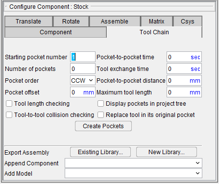
Starting pocket number — Use this field to set the number pockets will begin to be numbered with.
Number of Pockets — Use to define the number of tools in the tool chain. Then Vericut will automatically create this number of equally spaced tool components along the tool chain's perimeter geometry. The tool chain perimeter is defined by the first sweep model file attached to the tool chain component. This file is normally not displayed except for debugging purposes. Other models may be used to define the associated tool chain machine structure.
These tool components are named Pocket1, Pocket2, ..., PocketN. They are created each time the machine definition file is loaded, are not saved, and may not be edited. The position of Pocket1 is defined by the start point of the first boundary geometry segment (line or arc). Pocket1 is also defined as the "select" or "exchange" position. The perimeter geometry is scaled about Pocket1 to achieve the pocket-to-pocket spacing entered in the GUI. Normally this adjustment should be small.
Pocket order — Use to define the direction for pocket numbering. Select Clockwise or Counter Clockwise from the pull-down list.
Pocket offset — Use this field to determine how far away the pocket will be offset from the chain sweep model. For example, on circular chain sweep an offset of 2 will offset the pocket 2 units from the sweep. The sign of the value ± determine the direction of the offset out/in.
Pocket-to-pocket time — Defines the time (in seconds) required to move the tool chain one position.
Tool exchange time — Use to define the time (in seconds) required to move the selected tool into the machine's spindle and return the unloaded tool to the tool chain.
Pocket-to-pocket distance — Use to specify the distance between adjacent tool centers, along the tool chain's perimeter.
Tool length checking — When toggled "On", tool lengths are checked against the Maximum tool length value when they are initially put in the tool chain. If the tool length exceeds the Maximum tool length value, an error is output.
Maximum tool length — Use to specify the maximum tool length value used for Tool length checking.
Display pockets in project tree — Use to specify whether or not the tool chain's associated tool components are displayed in the project tree. When toggled "On", tool components will be displayed in the project tree. The default is not to display the tools components since large tool chains can contain a hundred or more tools.
Replace tool in its original pocket — Use to specify where the tool being unloaded from the spindle is to be placed in the tool chain. When toggled "On", the unloaded tool is returned to its original pocket position. Otherwise, the tool being unloaded is placed in the pocket emptied by the tool being loaded.
Tool-to-tool collision checking — Use to specify collision checking when a tool is placed in the tool chain during a tool exchange. When toggled "On", the tool being unloaded and returned to the tool chain is checked for collisions with the tools in adjacent pocket positions.
Create Pockets — Use to add pockets to the tool chain.
📝 NOTE: Before using the Create Pockets feature, the Tool Chain component must have a sweep model file representing the tool chain attached.
Component Type: All Motion Axes
The following picture shows the Component tab that applies to all Motion Axis (X Linear, Y Linear, Z Linear, A Rotary, B Rotary, C Rotary, U Linear, V Linear, W Linear, A2 Rotary, B2 Rotary, C2 Rotary) components. Notice that there is also an additional tab: Accel/Decel. Both of these tabs are described below.
SubSystem — Subsystem which commands a linear or rotary motion type component to move. Any alpha-numeric sub-system name can be entered (may include spaces) and is always considered as text. Enter "*" (without the quotes) for motion axes included in all machine subsystems. Subsystems are used in machines with multiple motion components that are commanded to move via the same G-Code word, for example "X". By default, a machine uses one subsystem for all motion components, assuming they are commanded to move via unique G-Code words.
When multiple motion components are driven by the same G-Code word, such as can occur in 4-axis lathes or mills with multiple independently controlled heads, define different subsystems to control which component moves when the motion command is processed. Then, configure the control so that other codes in the tool path activate the appropriate subsystem for movement. A full set of tables are available to support each machine subsystem.
Translucent — Toggle on (checked) to ensure component models are displayed as translucent (can be seen through).
The following features are specific to Motion Axes components, Turret components, and Track components:
Motion Axis — Specifies the axis of motion for a linear, rotary or turret type component, relative to the component coordinate system. Use a "moving tool philosophy" to specify the motion axis and direction, even though the component may actually move on the machine instead of the tool.
Reverse Direction — When toggled "On" (checked), reverses the component motion direction.
Rapid Rate — Feed rate for motion-type components moving in rapid positioning mode (e.g. G0). For linear motion components the value entered is units/minute where "units" reflect the units of the NC program file. For rotary motion components the value entered is degrees/minute.
Max Feed Rate — Specifies a maximum feed rate for components. Default is set to 150% of program.
Part Side — This feature enables you to specify whether you want Vericut to automatically calculate whether a component is "part side" or whether you want to manually specify whether or not a component is "part side".
A component is considered "part side", when one of its child components is a Stock component. If the component is "part side", based on Vericut's sense of the "moving tool philosophy", Vericut automatically reverses the direction of motion.
-
Auto — When Part Side is set to Auto (the default), Vericut automatically calculates whether or not the component is "part side" at "Reset".
-
Yes — Use this feature to manually specify that the particular component is "part side".
-
No — Use this feature to manually specify that the particular component is not "part side".
Turret Aid — Displays the Turret Aid window enabling you to specify turret component characteristics.
Optional Accel/Decel Settings
Acceleration — Velocity at which the NC machine component can accelerate. Values entered are units per second per second, where units could be inches or millimeters for linear axes, depending on the machine units, or degrees for rotary axes.
Deceleration — Velocity at which the NC machine component can decelerate. Values entered are units per second per second, where units could be inches or millimeters for linear axes, depending on the machine units, or degrees for rotary axes.
Max Velocity for Direction Change — Maximum feed rate for motions that cause an axis to decelerate to zero velocity, such as occurs when turning at a corner.
📝 NOTE: These Accel / Decel settings are used when calculating the Time displayed in the Status window if the “Apply Acceleration to Cycle Time” field is checked. These settings for the X, Y, and Z components are also used in the Accel/Decel calculations within Optimization if Accel/Decel is being applied for the current tool.
The remaining features on the Component tab for All Motion Axes components are described in the Common Features section above.
Accel/Decel tab
Features on the Accel/Decel tab are used to define the settings used by Vericut when calculating the Time value displayed in the Status panel.
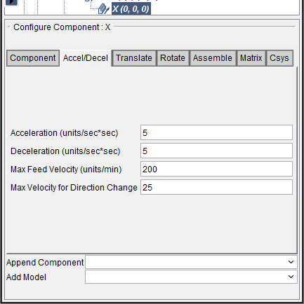
Acceleration — Velocity at which the NC machine component can accelerate. Values entered are units per second per second, where units could be inches or millimeters for linear axes, depending on the machine units, or degrees for rotary axes.
Deceleration — Velocity at which the NC machine component can decelerate. Values entered are units per second per second, where units could be inches or millimeters for linear axes, depending on the machine units, or degrees for rotary axes.
Max Feed Rate — Maximum speed axes can travel while in feed mode. The value entered is in units per minute, where units could be inches or millimeters for linear axes, depending on the machine units, or degrees for rotary axes.
📝 NOTE: For RAPID motion, the component’s Rapid Rate will be used.
Max Velocity for Direction Change — Maximum feed rate for motions that cause an axis to decelerate to zero velocity, such as occurs when turning at a corner.
📝 NOTE: These Accel / Decel settings are used when calculating the Time displayed in the Status panel if the “Apply Acceleration to Cycle Time” field is checked. These settings for the X, Y, and Z components are also used in the Accel/Decel calculations within Optimization if Accel/Decel is being applied for the current tool.
Moving Tool Philosophy
Vericut uses a "moving tool philosophy" to describe motion directions, and reflect how the machine maintains the tool-to-workpiece relationship. This philosophy is used regardless of whether the Tool or Stock component is actually moving. Examples follow.
Consider a standard 3-axis vertical milling machine where the Z-axis moves the tool up/down, and the X or Y-axis moves the workpiece.
Example 1
Z+ command causes the Z-axis to carry the tool in the Z+ direction relative to the workpiece. Therefore, using the "moving tool philosophy" describes positive motion direction as "Z+".
Example 2
X+ command causes the X-axis to carry the workpiece in the X- direction relative to the tool. In this case, the tool is considered to move in the X+ direction relative to the workpiece. Therefore, using the "moving tool philosophy" describes positive motion direction as "X+", even though the workpiece is moving in the X- direction.
Component Type: Spindle
The following picture shows the Component tab that applies Spindle components.
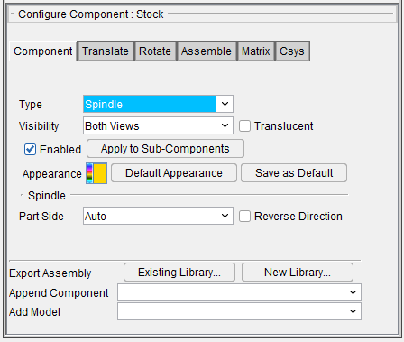
The Spindle features (Part Side and Reverse Direction) provide the same functionality described above for Motion Axes components.
The remaining features on the Component tab for Spindle components are described in the Common Features section above.
Component Type: Turret
The following picture shows the Component tab that applies to all Turret (Turret, A Turret, B Turret, C Turret) components.
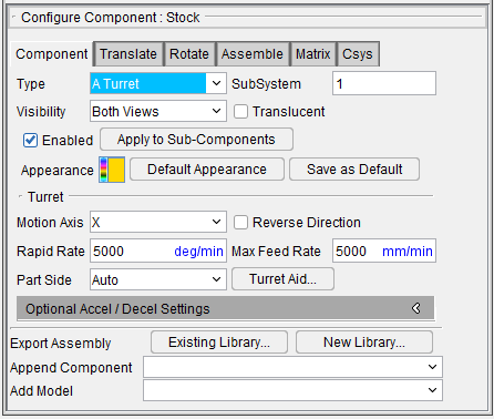
The Motion features (Motion Axis, Part Side, Reverse Direction, and SubSystem) provide the same functionality described above for Motion Axes components.
Time to Index (Seconds) — Use to specify the amount of time that it takes the turret to index. This value will be used in time calculations.
Turret Aid — Displays the Turret Aid window enabling you to specify turret component characteristics.
The remaining features on the Component tab for Turret components are described in the Common Features section above.
Turret Aid window
The features on this window are used to define turret characteristics.
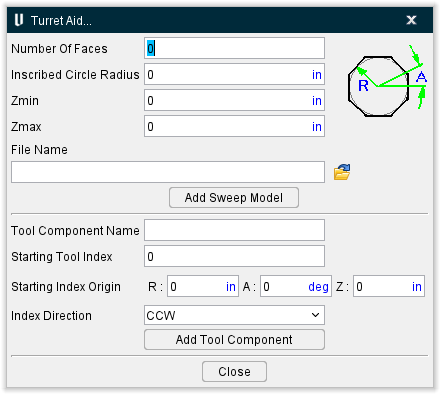
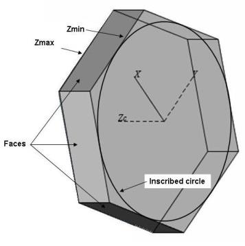
The features in the upper portion of the Turret Aid window enable you to easily create a swept solid model of a turret.
Number of Faces — Use to specify the number of faces on the perimeter of the turret.
Inscribed Circle Radius — Use to specify the radius of the inscribed circle that will be used to determine the size of the turret.
Zmin — Used to specify the starting location, along the Z-axis, to be used when creating a "swept" solid model of the turret. The distance between Zmin and Zmax determine the thickness of the turret.
Zmax — Used to specify ending location along the Z-axis to be used when creating a "swept" solid model of the turret. The distance between Zmin and Zmax determine the thickness of the turret.
File Name — Use to specify the file name for swept solid model file to be created. Enter the \path\filename in the File Name text field, or click on the  (Browse) icon and use the Save As file selection window that displays to specify the \path\filename.
Add Sweep Model — Creates a swept solid model using the above information and adds it to the Component Tree.
The features in the lower portion of the Turret Aid window enable you to easily create tool components for the turret.
Tool Component Name — Use to specify the base name for tool components to be created for the turret.
Starting Tool Index — Use to specify the starting index number to be used for the tool components created.
Starting Index Origin — The following features are used to describe the position of the first tool component on the turret. Think of the Starting Index origin as a polar location.
R — Use to specify the radial distance from the turret origin that the tool components will be placed.
A degrees — Use to specify the starting location polar angle, at which the first tool component is positioned. By default, if the number of faces is even, the starting location polar angle defaults to 0. If the number of faces is odd, the polar angle is .5(360/number of faces). That puts the default tool location at the center of a face in XY.
Z — Use to specify the Z location for the tool components. The default Z location is .5 (Zmax-Zmin).
Index Direction — Use to specify the direction around the turret that subsequent tool components will index from the first position. Choose Clockwise or Counterclockwise.
Add Tool Component — Creates the tool components and adds them to the Component Tree. A tool component will be created for each face on the turret. The tool component positions will be rotated around the turret origin by "number of faces"/360, and positioned the radial distance (R) away from turret origin and indexed in the specified direction from the Starting Index Origin angle (A). Components will be named "tool component name"1, "tool component name"2, etc., depending on the Starting Tool Index number chosen.
Close — Close the Tool Aid window.
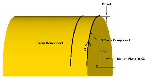
Component Type: Track
The following picture shows the Component tab that applies to all Track (X Track, Y Track and Z Track) components. Notice that there is also an additional tab: Accel/Decel. Both of these tabs are described below.
Motion Plane — Use this feature to define the motion plane for the Track component. Select XY, ZX, or YZ from the pull-down list.
Offset — Use to define the offset (the distance from the component that the Track component sits on to a reference point on the component that travels on the track.
From Component — Use to specify the component that the Track component sits on.
The picture below shows the relationship of the above features for an X Track component.
The Motion features (Part Side, Reverse Direction, Rapid Rate, and SubSystem) provide the same functionality described above for Motion Axes components.
Accel/Decel tab — Features on the Accel/Decel Settings tab are used to define the settings used by Vericut when calculating the Time value displayed in the Status panel.
The remaining features on the Component tab for Track components are described in the Common Features section above.
Component Type: Link
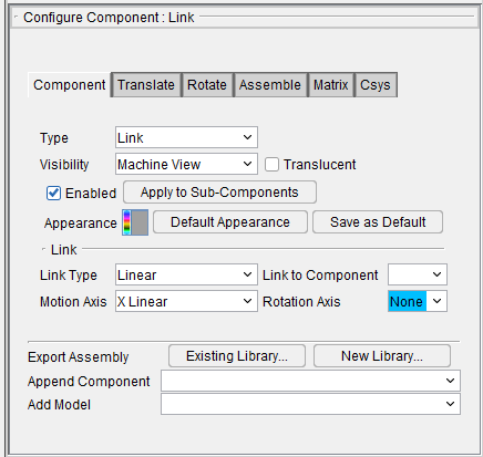
The following picture shows the Component tab that applies Link components.
Link to Component — The Link To Component feature enables you to specify another Link Component which this Link Component is connected to. Link components always exist in pairs.
Link Type — This feature enables you to define the link type between two links. Supported link types are Linear, Rotary, and Slider.
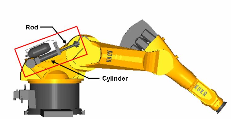
Linear Links
Linear type Links move parallel to its axis preserving direction between the link’s origin points.
In the following picture, the link components are shown in the red rectangle. Detailed information about configuring Linear Links can be found in the Using Link Components section of this document.
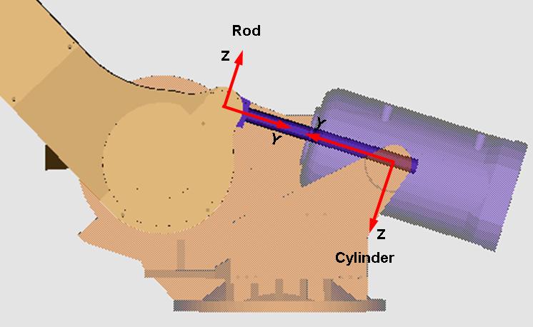
Linear Link Motion
Position 1
Position 2
Rotary Links
Rotary type Links rotate about specified rotary axis preserving their common intersection point established by link’s length.
In the following picture, the link components are shown in the red rectangle. Detailed information about configuring Rotary Links can be found in the Using Link Components section of this document.
The following strict rules must be adhered to make link motions work correctly:
- The link's rotation axis must cross a point on the parent component.
- The link's component origin must be located on the link rotation axis.
-
The link's secondary axis must be oriented toward:
The linked component's origin for "Linear" links.
The intersection point of linked components for Rotary links -
The Link Component can be attached to another link component (parent) only when parent component is linked.
Slider Links
In the following picture, the link components are shown in the red rectangle. Detailed information about configuring Slider Links can be found in the Using Link Components section of this document.
Slider type Links are similar to a Rotary type link component but it does not rotate about its rotation axis. Instead, it slides along the linear axis to preserve the distance between its rotary joint (with rotary link) and rotary link component center (rotary link length). The Slider link can only be paired with a rotary link. The coordinate system of a slider link should be placed in its joint with the rotary link. The Rotation axis must be same as the paired rotary link. The Motion axis is the next axis of the component matrix after the Rotation axis (📝 NOTE: next of Z is X).
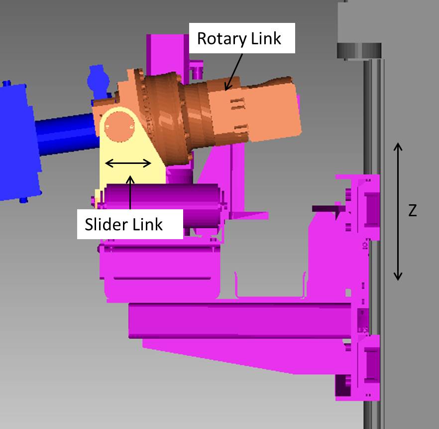
Slider Link Motion
Position 1
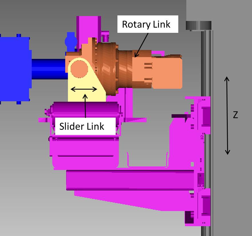
Position 2
Rotation Axis — This feature specifies an axis about which a link component can rotate (in link coordinate system). Select the axis from the pull-down list. Option Point is not supported yet.
Motion Axis — This feature specifies a linear axis along which a link component can move (in link coordinate system). Select the axis from the pull-down list.
📝 NOTES: Link Component is a passive component without any mechanical means to make a motion. Its motion is caused by its parent component and type of linkage with its linked component. The following strict rules must be satisfied to make links motions correct:
- Link’s rotation axis must cross a point on the parent component where link is attached to.
- Link’s Component matrix origin must be located on the link rotation axis.
-
Link’s secondary axis must be oriented toward (or opposite) to:
for Linear links — linked link origin
for Rotary links — intersection point of linked links. -
Link Component can be attached to another link component (parent) only when parent is linked.
See the examples in the Using Link Components section of Vericut Help for additional information.
The remaining features on the Component tab for Link components are described in the Common Features section above.
Using Link Components
The following examples illustrate how Link Components can be used.
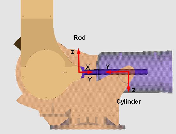
Example 1 – Linear Link Components
In the following picture, the link components are shown in the red rectangle.

Refer to the picture above and the Project Tree panels shown below to see how the linear link components are configured.
In the above example notice that link component "cylinder" and link component "rod" make up the required link component pair.
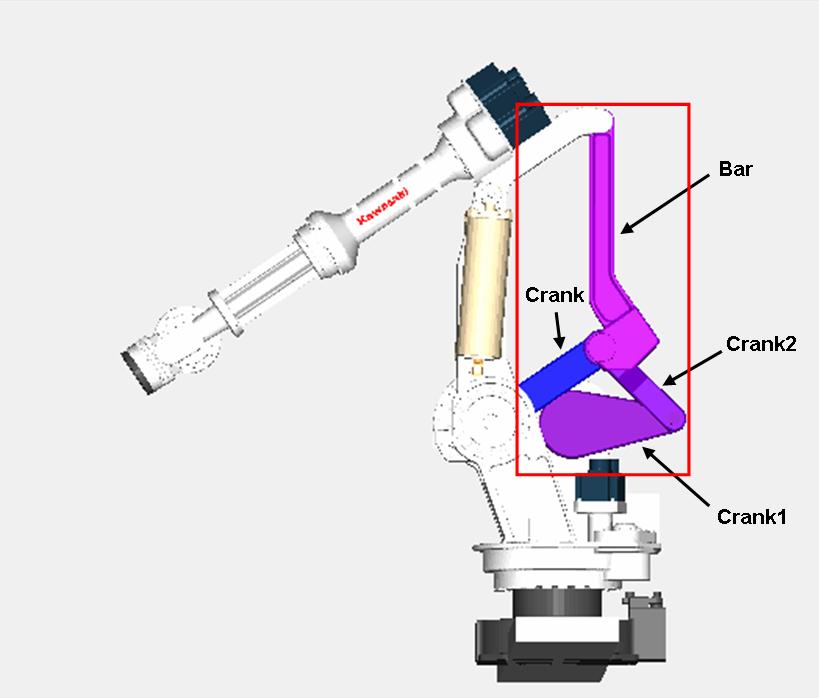
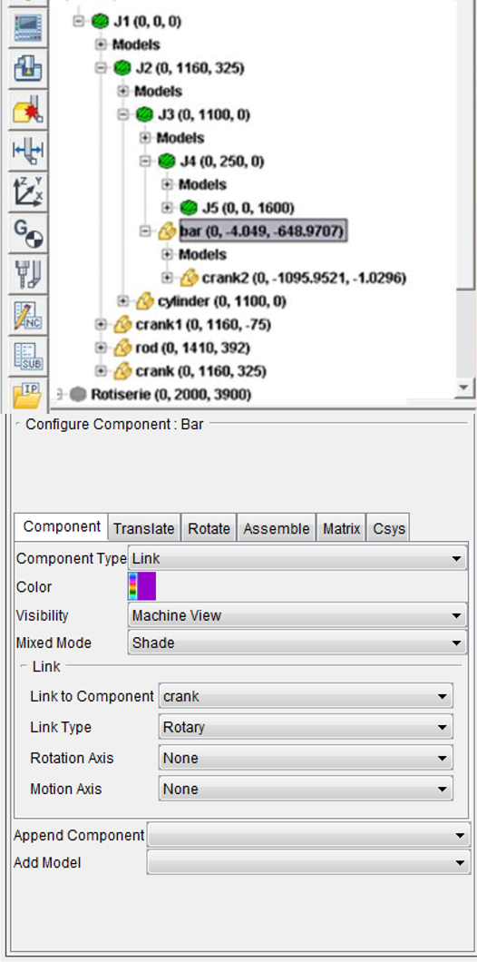
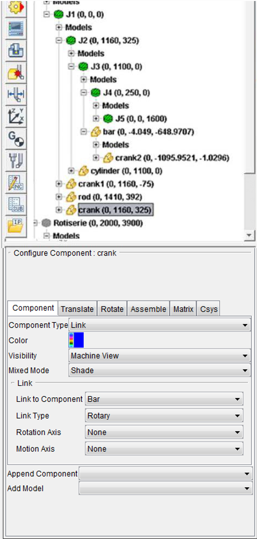
Example 2 – Rotary Link Components
In the following picture, the link components are shown in the red rectangle.

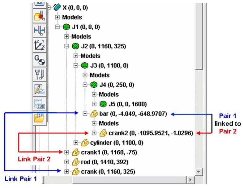
Refer to the picture above, and the Project Tree panels shown below to see how configure rotary link components and how multiple rotary link component pairs can also be linked together.
- The following Project Tree images show how link component "bar" and link component "crank" are configured to create "Link Pair 1".
- The following Project Tree images show how link component "crank1" and link component "crank2" are configured to create "Link Pair 2".
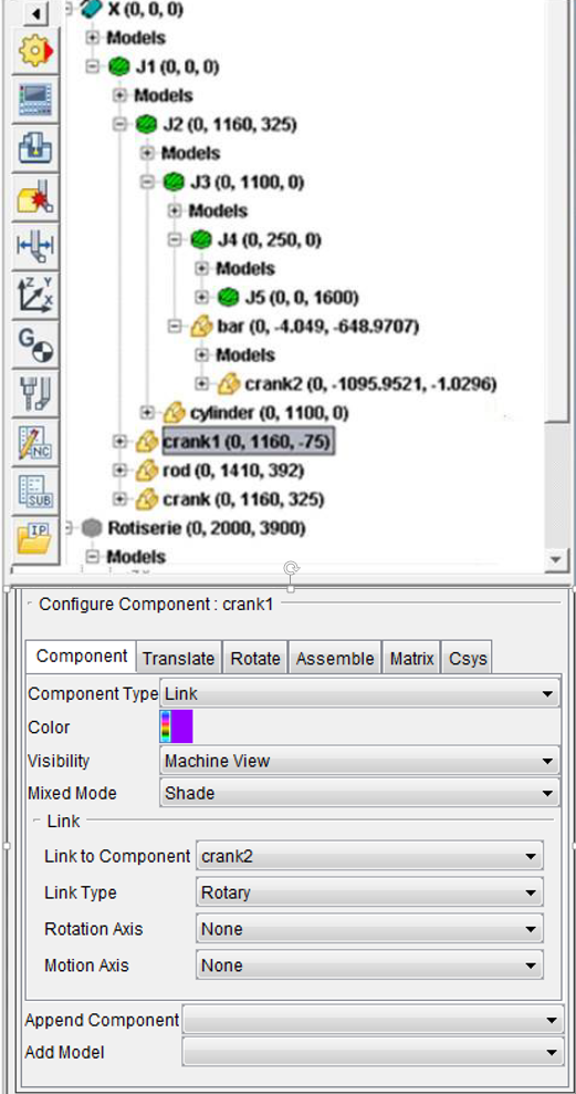
- The following Project Tree image shows how multiple link component pairs can be configured so that they can be linked together. Notice that link component "bar" from Link Pair 1 is the "parent" of link component "crank2". This relationship creates a link between Link Pair 1 and Link Pair 2.
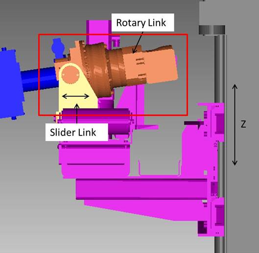
Example 3 – Slider Link Components
In the following picture, the link components are shown in the red rectangle.
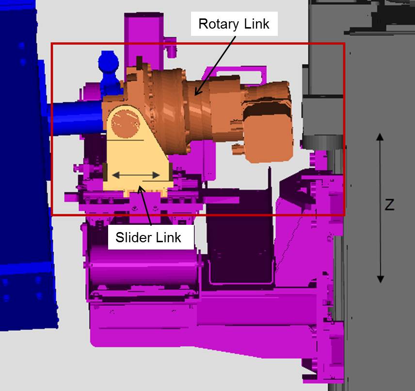
Refer to the picture above and the Project Tree panels shown below to see how the slider link components are configured.
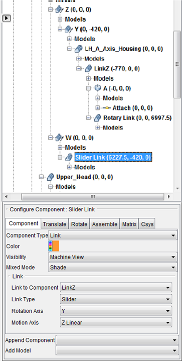
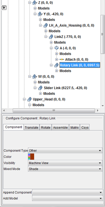
In the above example notice that link component "Slider Link" and link component "Rotary Link" make up the required link component pair.
See Component Type: Link section of Vericut Help for additional information on link components.
Component Type: Create robot structure from DH table
This functionality allows for the creation of a robot structure (and most notably, all its joints) from a Denavit-Hartenberg table, using as input the convention of “Classic DH parameters” (which is the most common convention).
📝 NOTE: The other convention, called “Modified DH parameters”, is not supported by this function.
📝 NOTE: This convention can be seen as a way of talking between robotics engineers. It allows to normalize, simplify and rationalize the geometrical modelling of a robot.
Right click on Machine base component -> Append -> Robot -> Create robot structure from DH table. The following dialog will appear:
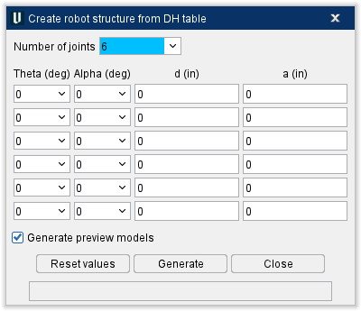
Number of joints — defines if we are going to build a 5 joints or 6 joints robot. If value 5 is selected, the 6th line associated to DH parameters will be disabled.
Then comes the table associated classic DH parameters. There is one line per joint definition. The first line describes the position of the frame of the joint 2 relatively to the frame of the joint 1. In the same way, the second line regards the joint 3 relatively to the joint 2, the third line the joint 4 relatively to the joint 3, and so on. The last line describes the position of the mount relatively to the last joint.
The position and orientation of a joint frame relatively to a previous frame are expressed with 4 unique parameters, which are called the DH parameters. It offers 4 degrees of freedom (instead of 6), which restrains how successive joints may be adjusted, but still allows any kind of conventional robot to be built. With classic DH parameters, we define frames which are located at the end of each joint.
In each joint relative frame, the joint direction will be associated to Z+, and the common normal will be associated to X+. The DH parameters are:
-
An angle Theta (positive or negative, in degrees) about previous Z-axis, from old X-axis to new X-axis.
-
An angle Alpha (positive or negative, in degrees) about common normal, from old Z-axis to new Z-axis.
-
A distance d (positive or negative), which is the offset along previous Z-axis to the common normal.
-
A distance a (positive or negative, and which is sometimes called r to avoid confusion with Alpha), which is the length of the common normal.
Generate preview models — allows the creation of automatically visualized models for joints, which will appear as a succession of cones:

Reset values — allows revert to default values for each field.
Generate — executes the generation of the robot structure. This structure will appear as a child to the Machine base component, with the first generated component being named “RobotBase-DH”. If such a structure existed already, it will be replaced automatically by a new structure which will match the dialog’s current values.
If the generation of the robot structure worked, the status field at the bottom of the dialog will show the following message:
“Robot generation is successful.”
This is also endorsed by the following message inside the Vericut Logger:
“Creation of robot from DH table successful.”
It means that the DH parameters allowed to build a functioning robot, and that automatic adjustments to make it compatible with Vericut robot logic were successful.
Even without setting SetRobotBaseCsys/SetRobotTipCsys/SetRobotCsys macros, it is possible to test the inverse kinematics of the robot with MDI Pick. In fact, the build includes following component types:
“Robot Base” (for the component “RobotBase-DH”).
“Robot Tip” (for the component “Tip-DH”).
… Which means they can be automatically recognized by robot logic.
A default Tool component is also automatically added, with proper orientation. If the generation of robot structure failed, the status field at the bottom of the dialog will show the following message:
“Robot generation failed!”
It can be caused by bad values in DH parameters associated to the robot or a failure when doing automatic adjustments to make it compatible with Vericut robot logic. Details about the problems will then appear as warnings inside the Vericut Logger.
Close — button allows to close the dialog.
📝 NOTE: During a project session, all values set in this dialog will be kept and remembered.
Component Type: 3DLive™
The following picture shows the Component tab that applies to 3DLive™ imports.
OK To Cut Into Fixture — Toggle this feature on (checked) to specify when it is acceptable to cut into a fixture. This feature is only available when Component Type is Fixture.
Maximum Milling Depth — After OK To Cut Into Fixture is on, this feature can be toggled on (checked) to specify the maximum depth, as measured along the tool axis, that a mill or tap cutter can cut into the fixture. A value of 0 will result in a "Maximum Milling Depth must be positive" message in the Logger and if you press Play, the feature will toggle itself off. This feature is only applicable to milling or tapping cuts. It is ignored for turning cuts.
The OK To Cut Into Fixture and Maximum Milling Depth features work together in the following ways:
Milling and Tapping Cuts
When OK to Cut Into Fixture is toggled "On" (checked) but the Maximum Milling Depth checkbox (described below) is toggled "Off" (not checked), all cutter/fixture collisions are ignored, no matter what value Maximum Milling Depth is set to.
When OK to Cut Fixture and Maximum Milling Depth checkbox are both toggled "On" (checked), cutter/fixture collisions are only reported if the collision depth is greater than the specified Maximum Milling Depth value, as measured along the tool axis.
Turning Cuts
For turning cuts, cutter/fixture collisions are not reported regardless of collision depth.
When OK To Cut Into Fixture is toggled "Off" (not checked), any cutter/fixture contact produces an error.
📝 NOTES:
-
The OK To Cut Into Fixture feature is only relevant for valid milling, tapping, or turning cuts. For instance, if a milling cutter collides with the fixture while in an invalid spindle state, this option will be ignored and the collision will be reported as usual.
-
The behavior described above applies only for cutter/fixture collisions. Holder collisions and other machine component collisions are not affected by the above check box states.
- Both settings are saved in the fixture component.
- Depth is measured along the tool axis.
The remaining features on the Component tab for 3DLive™ components are described in the Common Features section above.
Component Type: Import Assembly
The new assembly library file allows you to store assemblies in a library. An assembly is made up of components. They can be machine and/or attach components. New options have been added to the component branch right mouse shortcut menu and configure component menu to import and export assemblies from the library.
Import Assembly opens the Import Assembly window, enabling you to choose and copy an Assembly from a library and append it after the current component. You can access this feature in one of the following ways:
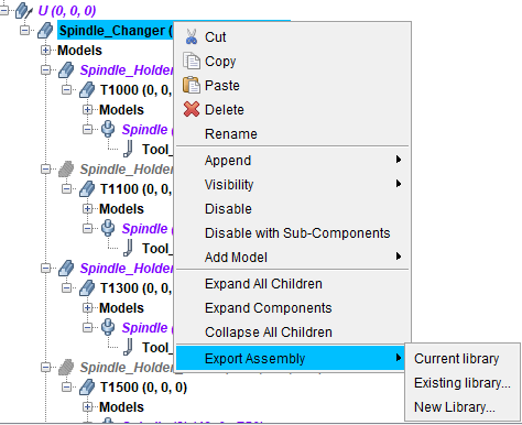
Export Assembly
Locations:
Project Tree > Component Branch Right Mouse Shortcut Menu
Project Tree > Component Branch > Configure Component menu
Export Assembly copies the selected component and its children to an Assembly and saves it to an assembly library file.
Current library — Adds the Assembly to the current or most recent assembly library file and saves the file.
Existing library… — Opens a file selection box to select which file to add the Assembly to and saves the file.
New library… — Opens a file selection box to create a new library file and saves the Assembly to it. If the name of the library file already exists, it will be replaced.
Import Assembly
Locations:
Project Tree > Machine Component Branch Right Mouse Shortcut Menu > Append
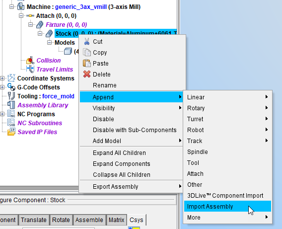
Project Tree > Component Branch > Configure Component menu > Append Component
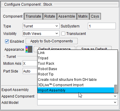
Import Assembly opens the Import Assembly window, enabling you to choose and copy an Assembly from a library and append it after the current component.
Import Assembly window
Using any of the above features opens the Import Assembly window, enabling you to specify the Assembly Library File to be imported.

Assembly Library File — Pulldown feature shows recently loaded Assembly library files and is used to select the Assembly Library file to be viewed.
Open File — Opens a file selection box to load a specified Assembly Library file.
Assembly — Displays the Assembly.
Import — Imports the highlighted Assemblies into the current project.
Close — Closes the Import Assembly window.