Tool Manager window, Tool Bar
The Tool bar, located across the top of the Tool Manager window, provides easy access to Tool Library functions. Each icon contains one function or a group of related functions. Left click on any icon to activate the function. If the icon or button includes a ![]() , click on the
, click on the ![]() to display the list of functions that are available for that icon or button. Click on the function in the list that you want to use. Each of the functions is described in detail below. The Tool Bar is composed of the five following tabs:
to display the list of functions that are available for that icon or button. Click on the function in the list that you want to use. Each of the functions is described in detail below. The Tool Bar is composed of the five following tabs:
Tool tab

File group
 (Open File) — Displays the Open file selection window enabling you to open an existing Tool Library file.
 (Recent) — Use to open recent files without having to navigate the Open file selection window.
 (New File) — Use to create a new Tool Library file.
 (Save File) — Use to save the current Tool Library file. If you do not have write privileges to the location of the current tool library file, the Save Tool Library As file selection window will display enabling you to save the current tool library to a different location.
 (Save As) — Use to save the current Tool Library file.The Save Tool Library As file selection window will display enabling you to save the current tool library to a different location.
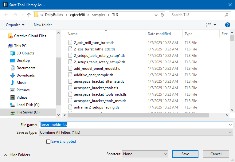
Save Encrypted — when toggled on (checked), this encrypts the saved file. Encryption is one-way process, meaning there is no “decryption” tool to extract the unencrypted files that were used to create it. Users that create encrypted TLS files are expected to retain and maintain the original files.
Add group
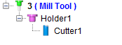
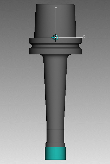
 (Mill) — Adds a Mill tool assembly after the highlighted tool in the Tool List. The tool assembly will consist of the Tool with a default Holder component and a default Cutter component as shown below.
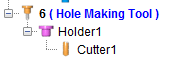
 (Hole Making Tool) — Adds a Hole Making tool assembly after the highlighted tool in the tool list. The tool assembly will consist of the Tool with a default Holder component and a default Cutter component as shown below.
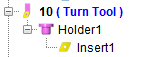
 (Turn) — Adds a Turn tool assembly after the highlighted tool in the tool list. The tool assembly will consist of the Tool with a default Holder component and a default Insert component as shown below.
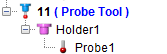
 (Probe) — Adds a Probe tool assembly after the highlighted tool in the tool list. The tool assembly will consist of the Tool with a default Holder component and a default Probe component as shown below.
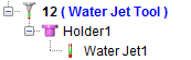
 (Water Jet) — Adds a Water Jet tool assembly after the highlighted tool in the tool list. The tool assembly will consist of the Tool with a default Holder component and a default Water Jet component as shown below.
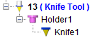
 (Knife) — Adds an Ultrasonic Knife tool assembly after the highlighted tool in the tool list. The tool assembly will consist of the Tool with a default Holder component and a default Knife component as shown below.
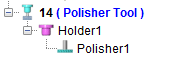
 (Polisher) — Adds a Polisher tool assembly after the highlighted tool in the tool list. The tool assembly will consist of the Tool with a default Holder component and a default Cutter component as shown below.
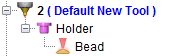
 (Additive Tool) — Adds an Additive tool assembly after the highlighted tool in the tool list. The tool assembly will consist of the Tool with a default Holder component and a default Additive Bead component as shown below.
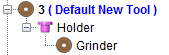
 (Grinder Tool) — Adds a Grinder tool assembly after the highlighted tool in the tool list. The tool assembly will consist of the Tool with a default Holder component and a default Grinder component as shown below.
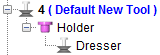
 (Dresser Tool) — Adds a Dresser tool assembly after the highlighted tool in the tool list. The tool assembly will consist of the Tool with a default Holder component and a default Dresser component as shown below.
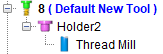
![]() (Thread Mill Tool) — Adds a Thread Mill tool assembly after the highlighted tool in the tool list. The tool assembly will consist of the Tool with a default Holder component and a default Thread Mill component as shown below.
(Thread Mill Tool) — Adds a Thread Mill tool assembly after the highlighted tool in the tool list. The tool assembly will consist of the Tool with a default Holder component and a default Thread Mill component as shown below.
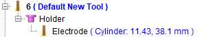
 (Electrode Tool) — Adds an Electrode tool assembly after the highlighted tool in the tool list. The tool assembly will consist of the Tool with a default Holder component and a default Electrode component as shown below.
 (Standard Hole-making Tool) — Displays the Standard Tool window enabling you to select tools from a Standard Tool Library. See Standard Tool window in the Tool Component tab (Hole Making Tool) section of Vericut Help for additional information.
 (Add a Component to the Selected Tool) — Use the following features to add tool components to the Tool List. Click on the part of the Add a Component to the Selected Tool icon to display a menu with the following options.
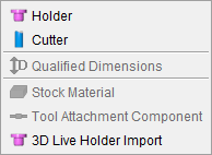
Holder — Adds a Holder component to the highlighted Tool.
Cutter — Adds a Cutter component to the highlighted Tool.
Qualified Dimensions — The Qualified Dimensions feature is only available for turning tools that use inserts created in a CAD system or STL inserts. This feature enables Vericut to correctly position and project the turning insert cutting faces on the turning plane. These are needed when cutting face of insert is far away from the machine component ZX plane. Having QD defined can improve accurate material removal.
Click on the turning tool so that it becomes highlighted. Click on the (Add a Component) icon in the Tool Manager window Tool Bar to display a menu. Select Qualified Dimensions in the menu to display the Tool Information tab as shown in the picture below.
You can also right-click on the turning tool so that it becomes highlighted and then select Add Qualified Dimensions in the menu that displays to display the Tool Information tab.
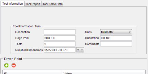
Use the Qualified Dimensions field in the Tool Manager, Tool Information tab to specify the Qualified Dimensions. See Qualified Dimensions in the Tool Information tab section of Vericut Help for additional information.
Stock Material — Opens the Add Stock Material Record window enabling you to add to the Stock Material Record tab.
Tool Attachment Component — This feature is used to define attachments for the Multi Tool Station (see below). The three tabs that appear once this feature is selected (Translate, Rotate, and Matrix) are identical to the Assembly tab features of the same names. Tool Attachments are usually driven along the Z axis.
![]()
3DLive Tool Import — Opens the 3DLive Machine Import window enabling you to read or import machine date for a .mch file. See 3DLive Machine Import for more info.
Multi Tool group
 (Multi Tool Station) — The Multi Tool Station command button is used to add a new tool holder to the Tool Manager which can hold multiple tools at a time. The holder that is created can be set up just like any other holder, through the Tool Component tab and the Assembly tab before adding additional tools. To create tool attachments for the Multi Tool Station, use the Tool Attachment component feature listed above. Tool attachments can also be defined via the Reference Tool. Multi Tools can be set to Static (stationary) or Live (driven) and the setting is applicable to all child sub tools. Multi Tools also have spin capability on M-code.
Edit group
 (Search Tool) — Displays the Search Tool window enabling you to search existing tool libraries for tools with specific attributes.
 (Undo) — Use this command button to “undo” changes made in the Tool Manager. The button will be grayed out until a change is made in the Tool Manager. Once a change is made, the button will display as shown here. Click on the button to “undo” the last change made to the Tool Manager. Click on the button again to “undo” the next to the last change and so on. There is no limit to the number of changes that you can “undo”.
 (Redo) — Use this command button to “redo” changes that you have used the Undo feature on. The button will be grayed out until the Undo feature is used. Once the Undo feature is used, the button will display as shown here. Click on the button to “redo” the last “undo”. Click on the button again to “undo” the next to the last “undo” and so on. There is no limit to the number of “undo” actions that you can “redo”.
 (Auto Gage) — Use this button to have Vericut calculate the highest point on the Z-axis of the tool and uses it for the Gage Point whenever a tool component is modified. This feature only applies to milling tools.
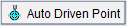 (Auto Driven Point) — Use this button to have Vericut calculate the driven point value whenever a tool component is modified.
On the Tool Manager Tool Information tab, select the Driven Point record having the value that needs to be adjusted and then click on the Auto Driven Point button. Vericut will calculate and adjust the values in the Driven Point record to reflect the tip of the tool.
Help group
 (Tool Manager Help) — Use this command button to open Vericut Help to the beginning of the Tool Manager section.
X-Caliper tab

The features on the X-Caliper tab of Tool Manager are identical to the features on Vericut's X-Caliper tab. Clicking the sections listed below will take you the relevant section of the Vericut Help that describes these features.
Feature/History group
The following features exist only in Tool Manager's X-Caliper tab:
Annotate group
This group functions similarly to Annotated Images with a few changes.
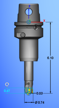
 Annotate Tool — Displays default dimensions for each tool listed in Tool Manager.
 Save Custom View — Allows dimensional changes and a View orientation to be saved for that specific tool.
 Remove Custom View — Deletes any dimensional changes and View orientation, setting the dimension display back to default.
Report tab
Report group
Features in this tab are used to create and view Tool Manager reports.
 Text — Displays the Save Tool Report window enabling you to create a and view a Tool Manager report in text format.
 HTML — Displays the Save Tool Report window enabling you to create a and view a Tool Manager report in HTML format.
 PDF — Displays the Save Tool Report window enabling you to create a and view a Tool Manager report in PDF format.
See Introduction to Vericut Reports, in the Getting Started section of Vericut Help for information on report template files supplied with Vericut.
 Report Template — Displays the Report Template window enabling you to select and/or modify an existing tool manager report template or create a new one.
 User-Defined Tag Values — Opens the User-Defined Tag Values window enabling you to assign/edit user-defined tag values used by the current tool manager report template.
View tab
Orient group
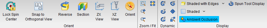
Lock Spin Center — sets the spin center on a desired area.
Snap to Orthogonal View — Snaps the current tool in the Tool Display area to the closest orthogonal view. Orient the tool so that it is close to the orthogonal view that you want and then click on the Snap to Orthogonal View icon and the tool will re-orient to the exact orthogonal view.
Reverse — Reverses the view.
Section — The features on the Section window enables you to define section planes through a Vericut model in a workpiece view. You can also define a section wedge through a Vericut model in a workpiece view.
ZX View — Changes the Tool Display area to a ZX view.
XZ View — Changes the Tool Display area to an XZ view.
Orient — Opens the Tool Manager View Orient window enabling you to orient the view of a tool or tool assembly. Features include: rotate, zoom, pan, reverse, etc.
Zoom/Fit group
Zoom In — see the To zoom in or out section for detail.
Zoom Out — see the To zoom in or out section for detail.
Zoom to Box — see the To zoom by “rubber banding” section for detail.
Dynamic Pan — see To dynamically pan section for detail.
Fit — see the To fit a model in a single view section for detail.
Display group
Shaded pulldown — choose between shaded and flat background options. See Background Style section of the View Attributes window for information on each option.
Shaded with pulldown — use this pulldown to select between various draw mode options. See Draw Mode section of the View Attributes window for information on each option.
Ambient Occlusion — When active, approximates how bright light should be shining on specific surface parts.
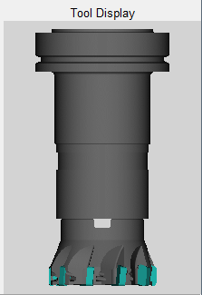
Spun Tool Display — When on, tools in the Tool Display Area will appear as they would when they are in use. This feature will remain active until it is toggled off (unchecked) or until you exit Vericut. Spun Tool Display is off by default at the start of each Vericut session. This feature can also be activated from the RMB menu in the Tool Display window.
| Standard view | Spun Tool Display active |
|---|---|
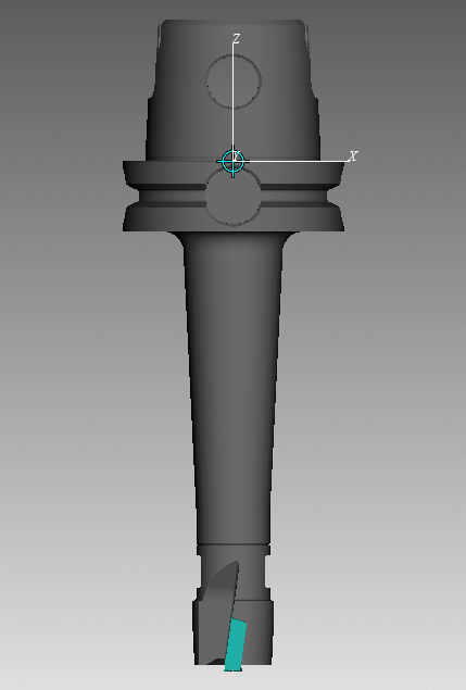 |
 |
Import tab
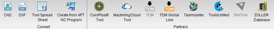
Convert group
 (CAD Tool) — Opens the Import CAD Tool window enabling you to read, extract, identify tool insert and holder solid models from a CAD system, and then import them into Vericut's Tool Manager. Currently, only STEP and CATIA V5 files are supported.
 (DXF Tool) — Opens the DXF Geometry window enabling you to import two dimensional geometry from files which comply with a de facto CAD system standard, the Data eXchange Format (DXF).
 (Tool Spread Sheet) — Opens the Import Tool Spread Sheet window enabling you to import tools from a spread sheet to Tool Manager.
 (Create from APT NC Program) — Causes the Tool Manager to scan the NC program files for cutter statements (including CUTTER, PPRINT-Vericut TC, etc.), and create a tool library file named
Partners group
 CoroPlus Tool — Displays the CoroPlus Tool Import Interface window enabling you to access tool assembly models and application data from CoroPlus ToolLibrary software.
 MachiningCloud Tool — Opens the Import MachiningCloud window enabling you to import tools from the machining cloud to Tool Manager.
 TDM — Displays the TDM Interface window enabling you to access tools from the TDM Systems', Tool Data Management (TDM) system database.
 Teamcenter — Displays the Teamcenter Connection dialog, enabling you to connect to Teamcenter. See Import Teamcenter Tools window for more information on using this system.
 ToolsUnited — Displays the TolsUnited window enabling you to use that interface for importing tools. See ToolsUnited section for more information on this system.
 WinTool — Displays the (WinTool) WT-ToolExport dialog by launching the executable directly from the Vericut Tool Manager Import ribbon. The WinTool button should be automatically active if WinTool software is installed and detected. For additional information, please see Configuring the WinTool Interface section.
 ZOLLER Database — Displays the ZOLLER Database Access window enabling you to retrieve tool data from ZOLLER Database Service and import selected tools from a setup sheet in the ZOLLER database to the Vericut Tool Manager.
Utilities tab
File group
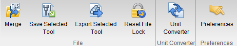
 (Merge) — Opens the Merge Tool Library window enabling you to merge two tool libraries into one.
Merge Tool Library window
Locations:
Tool Manager: Utilities tab >  (Merge)
The Merge Tool Library window has features that enable you to quickly, and easily, merge two tool library files.
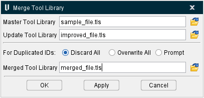
Master Tool Library — Enter the /path/filename, of the master tool library file, in the MasterTool Library text field or click on the  (Browse) icon to display the Open file selection window and use it to specify /path/filename of the master tool library file.
Update Tool Library — Enter the /path/filename, of the tool library file that will be merged into the master tool library file, in the Update Tool Library text field, or click on the (Browse) icon to display the Open file selection window and use it to specify the /path/filename of update tool library file.
For Duplicated IDs — Use to select one of the options to specify how duplicate tool IDs are to be handled during the merge operation.
Discard All — When toggled "On", duplicate tool IDs in the Update Tool Library will be discarded.
Overwrite All — When toggled "On", duplicate tool IDs in the Master Tool Library will be overwritten by the ones in the Update Tool Library.
Prompt — When toggled "On", a window will display when a duplicate tool ID is encountered, enabling you to specify whether to Discard the duplicate tool ID in the Update Tool Library, or Overwrite duplicate tool ID in the Master Tool Library, or to Quit the merge operation.
Merged Tool Library — Enter the /path/filename, for the merged tool library file, in the MergedTool Library text field, or click on the (Browse) icon to display the Save Tool Library As file selection window and use it to specify the /path/filename of the merged tool library file.
OK — Starts the merge operation and closes the Merge Tool Library window.
Apply — Starts the merge operation and leaves the Merge Tool Library window open for additional merges.
Cancel — Closes the Merge Tool Library window without doing the merge operation.
See Merging Tool Libraries section of Vericut Help for information about using the Merge Tool Library window.
 (Save Selected Tool) — Use to save the selected tool to a specified tool library file. Selecting Save Selected Tool displays a file selection window enabling you to specify a /path/filename for the tool library file.
 (Export Selected Tool) — Use to export the highlighted tool in the specified format (STL). Selecting Export Selected Tool displays a file selection window enabling you to specify a /path/filename for the file to receive the exported tool data.
You can choose to export any individual component in the tool assembly by selecting that component in the Tool Manager table, and then choose the Export Selected Tool option:
The following tool component will be exported to the specified file.
Or you can export the entire tool by selecting the tool's ID, and then choose the Export Selected Tool option.
The following tool assembly will be exported to the specified file.
The origin of the exported STL model corresponds to the tool's origin as seen in Tool Manager.
The accuracy of the exported model is controlled by Vericut's Model Tolerance feature located on the Settings window: Properties tab (Project tab > Settings > Properties tab).
📝 NOTE: For a change to Model Tolerance to take effect in the Tool Manager, the Tool Manager window must be closed when the tolerance is changed, then re-opened.
Using the Export Selected Tool feature
To change the exported tool model tolerance:
-
Ensure that the Tool Manager window is closed.
-
Open the Settings window: Properties tab (Project tab > Settings), and note the current Model Tolerance value used for simulation purposes.
- Change the Model Tolerance value as desired for the tool export operation and click OK.
To export the tool to the specified file:
-
Open the Tool Manager, select the tool (or tool component) to export, then select Tool Manager File menu > Export Selected Tool > model format (STL).
-
In the file selection window that displays, specify the \path\filename of the file to receive the exported tool data, then click Save.
When finished, reset the Model Tolerance value back to its original value.
 (Reset File Lock) — Enables you to delete an existing Tool Library file lock. Selecting Tool Manager, Utilities tab > Reset File Lock will display the following message with the logon ID of the user that currently has the Tool Library file locked.
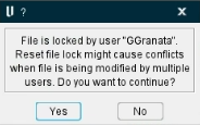
Select “Yes” to delete the file lock. Select “No” to cancel the action.
Tool Library File Locking
A Tool Library file locking mechanism is enabled by default. When locking is enabled, a lock file is created when a user opens a tool library file in Tool Manager. When a second user opens the same tool library file, Tool Manager checks for the existence of a lock file. If a lock file exists, the following warning is displayed:
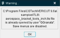
Select “OK” to open a read only version of the Tool Library file.
Save, Save As, Save Selected Tool options are disabled. The options stay disabled until a different unlocked file is loaded or by the options New File or Close are used.
The lock file name = “~vc” + tool library file name + “.lck”.
For example: ~vcvericutm.tls.lck.
The lock file is created in the same folder where the tool library file is located.
The Tool Library file locking feature can be turned off by setting an environment variable:
Set CGTECH_TOOL_LIB_LOCK=FALSE.
📝 NOTES:
-
If the Tool Library file is read only, then no lock file will be created.
-
If unexpected Vericut termination occurs, but the Java Runtime Environment (JRE) is able to “exit” gracefully, then the lock file is deleted. But if unexpected Java Runtime Environment (JRE) termination occurs, then the lock file is not automatically deleted and will have to be deleted manually.
Unit Converter group
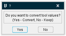
 (Unit Converter) — This command button converts selected tools from inch to millimeter or from millimeter to inch measurements depending on what the current values in use are. It converts Stock Material Record, driven point and cutter comp values, any tool type and component type. Multi tool selection is also possible. When a user performs a tool unit change by clicking on the new button or by changing tool unit from the tool page, a new pop up message comes up, asking the user to convert values or keep them as is.
Preferences group
 (Preferences) — Use this command button to open the Tool Manager Preferences window.