Tool Manager window, Tool Parameter Definition Area
The Tool Parameter Definition Area, located in the center of the Tool Manager window between the Tool List Area/Coordinate Systems List Area and the Tool Display Area, will display various windows depending on what is currently selected in the Tool List Area. These windows will enable you to define/edit tool components, define Coordinate Systems, and define other tool properties like Driven Point, Cutter Compensation values, etc. Each of the windows and the features contained on them are described in the sections that follow.
Tool Information tab — The Tool Information tab is displayed when a tool record in the Tool List Area is highlighted or whenever a new tool assembly is added. The Tool Information tab also has additional sub tabs that appear depending on various settings:
-
Cutting Limits tab — This feature is only available when optimization is used, it enables you to manipulate stock material for Tool Manager.
-
Optimization tab — This feature is only available when optimization is used, it enables you to fine tune optimization options for your tools.
Tool Definition window — The Tool Definition window enables you to define tool component shape, color, location, and other attributes. This window has additional tabs to help define tools:
-
Tool Component tab — This feature is used to define the shape of a tool component in a tool assembly
-
Assembly tab — This feature is used translate or rotate a component in a tool assembly, or to move the selected component by assembling (mating or aligning) it with other objects in the tool assembly.
Configure Coordinate System window — The Configure Coordinate System window is displayed when a Csys record in the Coordinate Systems Area is highlighted or whenever a new coordinate system is added.
Tool Manager window, Tool Information tab
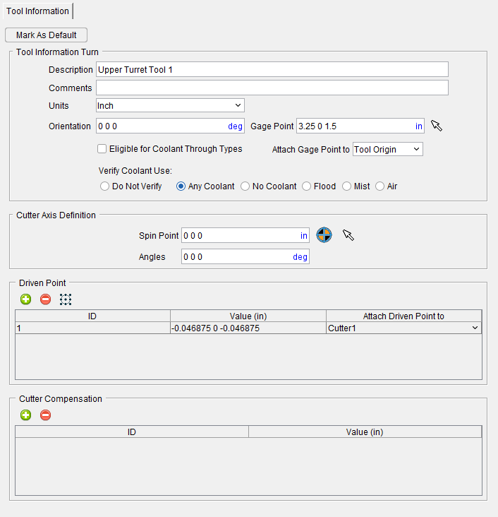
The Tool Information tab is displayed when a tool record in the Tool List Area is highlighted or whenever a new tool assembly is added.
 Mark as Default — Use to specify an existing tool as the default tool for that tool category. Default tools become the base tool whenever a new tool is added in the Tool Manager. Each tool category can have only one default tool at most.
Once Mark as Default is selected, the file ‘default_tools.prefs’ is added to the User preferences at the ‘%APPDATA%/Roaming/CGTech location. The file is updated whenever a new default is selected.
📝 NOTE: Marking a tool as a default cannot be undone. That selected tool remains as the default for that tool category until a new default is selected so care must be taken when selecting a default.
Imported elements of a tool (such as CAD, SOR, or Sweep) will not be carried over to the default tool preference file. Cutters and inserts are also not carried over meaning that cutters and inserts do not become the default tool components for their category. Holders are carried over unless “Do Not Add Holders” is toggled on (checked) in the ‘Preferences’ dialog of Tool Manager.
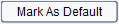
Static/Live (Driven) toggle — This option only appears for Multi Tool Station tool components. Use this feature to choose between a station that holds static tools and one that holds live or driven tools where the spin axis is set by the tool attachment's Z axis.
Description — Use to enter, and display a description for a tool/tool assembly record. Any alpha-numeric text can be entered in this field. Special characters are not recommended.
The Description field is also used to enter, and display, the cutter compensation value for Cutter Compensation records and to enter, and display, the X,Y,Z coordinate values of the driven point for Driven Point records.
Comments — This field enables you to add comments related to the tool/tool assembly. The comment text is stored with the tool ID.
See Specify Other Tool Properties section of Vericut Help for additional information on using the features described above.
Units — Use to enter, and display, the unit measurement system (Inch or Millimeter) in which the tool is defined. If the tool units are different from the Vericut session units when loaded, then tool description values are converted appropriately.
Orientation — Use to specify, and display, the orientation of the tool assembly when loaded for cutting. Three values are entered (separated by spaces) to define the X, Y, Z rotation angles, respectively. Angle values are in degrees, relative to the tool origin. Rotation occurs about the tool's gage point.
📝 NOTE: This feature is only applicable when NC Program Type is G-Code Data.
Gage Point — Use to enter, and display, the location of the tool assembly gage point. By default, the gage point is located at the tool origin. Values entered move the gage point relative to the tool origin, or you can select a gage point by clicking in the Gage Point field then clicking on the tool in the Tool Display Area (ref. Tool Manager, Tool Display Area section of Vericut Help). As you move the mouse over the tool, a point and normal vector show you the pending pick-point location.
There is also a mouse icon ![]() which can be used to manually select a Gage Point. Simply click on the icon to activate mouse pick selection for Gage Points. Then left-click on the part of the tool in the Tool Display section to get the XYZ values for your Gage Point. Alternatively, you middle-click (click with the mouse wheel) to select a feature which will provide only Z values for the Gage Point.
which can be used to manually select a Gage Point. Simply click on the icon to activate mouse pick selection for Gage Points. Then left-click on the part of the tool in the Tool Display section to get the XYZ values for your Gage Point. Alternatively, you middle-click (click with the mouse wheel) to select a feature which will provide only Z values for the Gage Point.
When processing G-Code NC programs, Vericut uses the gage point in the following two ways:
-
Controls how the tool loads in the NC machine — When a tool is loaded for cutting, the Gage Point is located at the NC machine's Tool component origin.
-
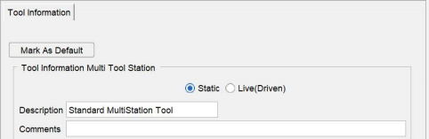
When a Gage Offset Table (ref. Gage Offset Table in the Tool Offsets Tables section of the Settings window: G-Code Advanced tab) is used to calculate the driven point needed to drive the tool in Tool Tip and Tool Length Compensation programming methods (ref. Programming Method on the Configure Setup menu, G-Code tab), Vericut uses the Gage Point to determine where the driven point (a.k.a. "control point") is located, relative to the gage point.
Missing or incorrect gage point values will cause a tool to load incorrectly on a 3-D machine and cause improper cutting.
Sample gage points for milling tools:
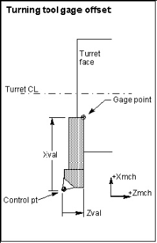
Sample gage points for turning tools:
The "Gage Point" view attribute displays a hollow target symbol  , at the gage point location (ref. Tool Manager: Tool Display Area right mouse button menu section of Vericut Help).
📝 NOTE: While a Gage Offset Table can still be used to specify the gage offset values required to calculate the driven point (ref. Gage Offset Table in the Tables for Processing G-Codes section, in the Vericut Help Library), the recommended method of specifying the driven point is to add one, or more, Driven Point records to the tool in Tool Manager. Then use the GageOffsetDrivenPoint macro to specify the Driven Point record to use for the tool motion. This method does not use a Gage Offset Table. For more information on the GageOffsetDrivenPoint macro, and all Vericut macros, see the Vericut Macros section, in the Vericut Help Library.
When using a Gage Offset Table, Vericut uses the gage offset to calculate where the driven point (aka "control point") is located relative to the gage point. When using Driven Point records, Vericut uses the driven point offsets in the Driven Point record to calculate the driven point relative to Tool Tip Zero.
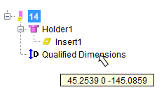
Qualified Dimensions — The Qualified Dimensions feature is only available for turning tools that use inserts created in a CAD system or STL inserts. When a turning tool is created with this type of insert two things take place. First, a Qualified Dimension field is added to the Tool Information tab for the tool as shown in the Tool Information tab picture on the following page.
Second, a Qualified Dimensions record is added to the tool assembly in the Tool List Area as shown in the picture below. Holding the cursor over the Qualified Dimensions record will display a tip with the current values of the record as shown in the picture below.
This feature enables Vericut to correctly position and project the turning insert cutting faces on the turning plane.
Click on the turning tool so that it becomes highlighted. Click on the ![]() part of the
part of the  (Add a Component to the Selected Tool) icon in the Tool Manager window Tool Bar to display a menu. Select Qualified Dimensions in the menu to display the Tool Information tab.
You can also right-click on the turning tool so that it becomes highlighted and then select Add Qualified Dimensions in the menu that displays to display the Tool Information tab.
Tool Information tab
The qualified dimension and driven point location are often coincident. When adding a Qualified Dimension record, it will default to the same 3 values as the first driven point if one exists. When adding the first driven point it will default to the same 3 values as the Qualified Dimension if one exists.
When the first Driven Point in the list is modified, the Qualified Dimensions are set to the same values, but not the other way around. Changing the Qualified Dimensions does not change the Driven Point.
The Qualified Dimension can be modified as need by editing the values in the Qualified Dimensions field.
When a Qualified Dimension is added, a turning plane is also created. The turning plane defaults to the ZX plane of the “orientation” of the tool (how it is mounted in the tool component). When orientation is 0,0,0, then it is the same as the ZX plane of the tool origin. The turning plane direction is indicated to be the Y-axis of the tool orientation axis by the presence of a Y in the pull-down list next to the Qualified Dimensions field. Another axis can be specified by selecting the desired axis from the pull-down list.
Examples
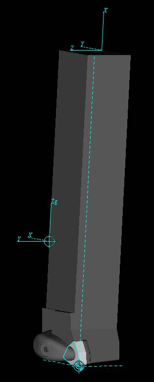
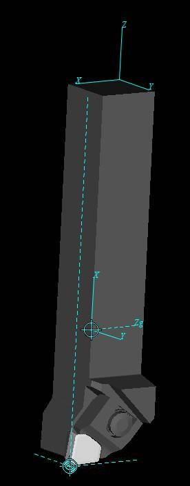
| For the tool in the picture below, the X-Y plane goes through the Qualified Dimensions point, and the cutting plane direction will be along the tool’s Z-axis. | For the tool in the picture below, the X-Z plane goes through the Qualified Dimensions point, and the cutting plane direction will be along the tool’s Y-axis. |
|---|---|
 |
 |
Eligible for Coolant Through Types — Use to define Tool eligibility to receive coolant through types during machining. During Vericut simulation if one of CoolantAirThru or CoolantThru macros are enabled, Vericut will generate an error message in case Eligible for Coolant Through Types box is not checked for the active tool. Eligible for Coolant Through Types feature is available for Mill, Hole-Making, Turning, Multi-Station, Thread Mills and Polisher tool type.
Attach Gage Point to — Use to associate the tool's Gage Point relative to the tool origin, or to a specific holder component in the tool assembly. When a holder with attached Gage Point is moved, the Gage Point also moves equally with the holder so it retains the same position relative to the holder.
Verify Coolant Use — Use these toggles to specify which coolant type must be used (or to specify that no coolant will be used). When specified coolant type is not set, Vericut will produce an error message informing you of the mismatch. Only one option can be active at any time. Certain options will require more specific types of coolant. The following options are always available:
-
Do Not Verify — Vericut will not check for coolant mismatch.
-
Any Coolant — Specifies that all external coolant types are acceptable.
-
No Coolant — Specifies that coolant is not to be used and Vericut will warn you if there is coolant use.
-
Flood — Specifies that only external flood coolant (includes all liquids) will be used.
-
Mist — Specifies that only external mist coolant (includes all aerosols) will be used.
-
Air — Specifies that only external air coolant (includes all gases) will be used.
The following Verify Coolant Use options are only available when Eligible for Coolant Through Types is toggled on (checked):
-
Through-Spindle — Specifies flood coolant will be delivered from within the spindle rather than being applied externally. This option requires that only synthetic coolant be used.
-
Through-Air — Specifies air coolant will be delivered from within the spindle rather than being applied externally.
Cutter Axis Definition
Use the features of this group to adjust the spin axis of angle head and driven type tools when the spin axis of the tool is not aligned the same Z axis of the Gage Point. This is particularly necessary when a tool assembly is built from holder to tip (per ISO 13399) instead of tip to holder.
Spin Point — Use to enter an X Y Z coordinate value to define the location of the spin point (typically at the tip of the tool or the Driven Point). This will display a CIP (Coordinate system In Process) coordinate system at the entered location once a value other than 0 0 0 is defined. You can also use the  (Use the driven point) icon to automatically align the Spin Point to the same location fo the first defined Driven Point. The Spin Point field will display greyed out and uneditable. If the Driven Point values changes the Spin Point will automatically update. Or use the
 ![]() (Pick the spin point) icon to define a location anywhere on the tool assembly for the Spin Point. Any surface vector of a tool assembly can be selected.
(Pick the spin point) icon to define a location anywhere on the tool assembly for the Spin Point. Any surface vector of a tool assembly can be selected.
Angles — Use this feature to specify the absolute XYZ rotation of the Spin Point (CIP) coordinate system, separated by spaces.
📝 NOTE: It is helpful when defining the Spin Point of a tool assembly to display the tool spinning in Tool Manager (RMB in the Tool Manager View > Spun Tool Display)
Driven Point/Focal Point — Use to add one or more Driven Point records to the highlighted tool. Click on the ![]() icon to add Driven Point records to the list. This option becomes Focal Point when used in conjunction with the Additive tool.
icon to add Driven Point records to the list. This option becomes Focal Point when used in conjunction with the Additive tool.
To remove a record from the list, select the record that is to be removed so that it becomes highlighted and then click on the ![]() icon.
icon.
Click the ![]() Display Driven Point grid icon to display the available 3 x 3 grid points and black circle representing the nose radius of turning inserts. Hover over any of the 9 available points and Right Mouse Button to Add Driven Point to Grid Point or Modify Driven Point to Grid Point any of the existing location points.
Display Driven Point grid icon to display the available 3 x 3 grid points and black circle representing the nose radius of turning inserts. Hover over any of the 9 available points and Right Mouse Button to Add Driven Point to Grid Point or Modify Driven Point to Grid Point any of the existing location points.
📝 NOTE: While the ![]() Display Driven Point grid icon is active, Driven Point Values are non-editable. Once the icon is inactive, the Driven Point Values can be edited.
Display Driven Point grid icon is active, Driven Point Values are non-editable. Once the icon is inactive, the Driven Point Values can be edited.
📝 NOTE: See Suggested Workflow for Importing Turning Tools for more information.
Vericut assigns a default ID but you can modify it if you choose by double clicking on the current ID value so that it becomes highlighted and then edit the value as desired. Vericut assigns a default Driven Point value of 0 0 0 but you can modify it by double clicking on the current value so that it becomes highlighted and then edit it as desired.
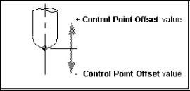
This feature is used to specify an offset for the tool control point, or "driven point". Material is removed based on motion commands and the tool shape relative to the control point. For milling tools, a positive value moves the control point in the positive tool axis direction (closer to the spindle), while a negative value moves the control point in the opposite direction.
📝 NOTE: Vericut material removal for milling tools does not support driven points with X- or Y- offsets, only Z-offsets are allowed. If you wish to drive the machine with an X, or Y, offset driven point, and to have the correct material removal, you should define 2 driven points for the tool. For example, to drive the machine with an X offset, create the 1st driven point (0,0,0) and the 2nd (6,0,0).
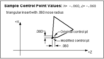
For turning tools, XYZ values (separated by spaces) are entered relative to the spindle axis (Z), and cross-slide axis (X).
Sample Driven Point values for a milling tool:
Sample Driven Point values for a turning tool:
When defined, the "Driven Point" view attribute displays as a hollow target symbol  at the control point location. (ref. Tool Manager: Tool Display Area right mouse button menu section of Vericut Help).
Attach Driven Point to — Use to associate the tool's Driven Point to a Cutter component so that if the cutter is moved in the tool assembly, the driven point stays connected in the proper relationship to the cutter. The “Tool Origin” option can be used to define a static driven point location.
Cutter Compensation — Use to add one or more Cutter Compensation records for the highlighted tool. Click on the ![]() icon to add Cutter Compensation records to the list.
icon to add Cutter Compensation records to the list.
To remove a record from the list, select the record that is to be removed so that it becomes highlighted and then click on the ![]() icon.
icon.
Vericut assigns a default ID but you can modify it if you choose by double clicking on the current ID value so that it becomes highlighted and then edit the value as desired. To modify the current Cutter Compensation value, double clicking on the current value so that it becomes highlighted and then edit it as desired.
Additive Functions
While most tools have a Cutter Compensation section, Additive tools have an Additive Functions section as Additive tools do not user cutter compensation. This section, as shown below, contains several unique functions that enable you to have maximum control over your Additive tool. Toggle the following options on (checked) to be able to define values for each function in their respective value fields.
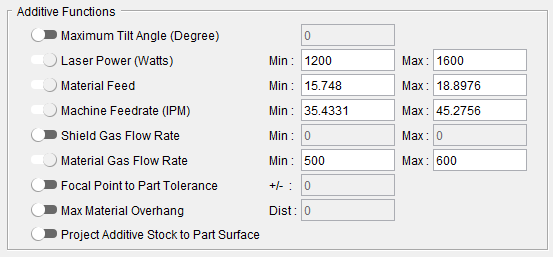
Maximum Tilt Angle (Degree) — Checks if the Additive tool is tilted beyond the specified maximum angle, as measured from vertical orientation. If an Additive tool is used beyond the manufacturer’s recommended tilt limits, the tool can experience reduced function or become damaged.
Laser Power (Watts) — Defines a minimum and maximum power value for your Additive laser.
Material Feed — Defines a minimum and maximum value for material feedrate.
Machine Feedrate (IPM) — Defines a minimum and maximum value for machine feedrate.
Shield Gas Flow Rate — Defines a minimum and maximum value for shield gas flowrate.
Material Gas Flow Rate — Defines a minimum and maximum value for material gas flowrate.
Focal Point to Part Tolerance — Defines the laser's focal point alignment relative to the part surface.
Max Material Overhang — Alerts user to excessive overhang conditions by sending warning messages to the Vericut Logger.
Project Additive Stock to Part Surface — Depending on bead overlap rate, additive material can build unevenly. When this option is toggled on (checked), Vericut will project what this uneven buildup of material will look like including displaying overlaps, acute corners, and double-deposits of material.
Tool Definition window
Locations:
Project tab > Tools: Tool Library tab > Tool Add group
Project tab > Tools: Tool List Area > Right mouse button menu > Add Tool > tool
The Tool Definition window enables you to define tool component shape, color, location, and other attributes. The features displayed on the Tool Component tab will vary, depending on the tool/tool component type that you selected to add/modify. Each of the Tool Definition window variations will be defined in detail in the linked sections. The Tool Definition window for Mill Cutters is shown in the picture below.
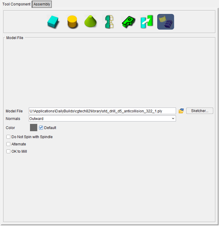
Tool Component tab — Features on this tab are used to define the shape of a tool component in a tool assembly. Features displayed on the Tool Component tab vary, depending on the tool/tool component type that you selected to add/modify.
Assembly tab — Features on this tab are used translate or rotate a component in a tool assembly, or to move the selected component by assembling (mating or aligning) it with other objects in the tool assembly.
Also see: Tool Component tab, Common Features
See Adding a Tool to a Tool Library section of Vericut Help for additional information about creating tool components.
Tool Manager window, Configure Coordinate System window
The Configure Coordinate System window is displayed when a Csys record in the Coordinate Systems Area is highlighted or whenever a new coordinate system is added.
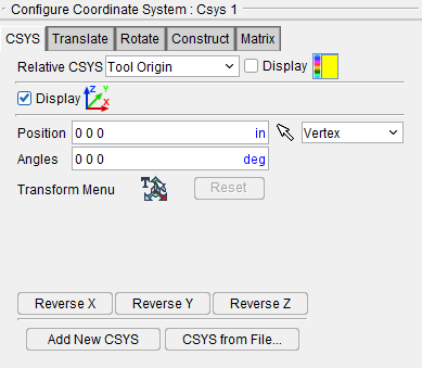
The Configure Coordinate System window provides features that enable you to define, or modify a coordinate system, also known as a "CSYS". Changes made in the Configure Coordinate System window are applied to the coordinate system that is highlighted in the Coordinate Systems Area. The Name of the coordinate system that the changes will be applied to is also shown at the top of the Configure Coordinate System menu. In the picture above, all changes will be applied to Csys 1.
All of the features found in the Configure Coordinate Systems window and its tabs are identical to those found on the Project Tree, Configure Coordinate Systems menu and are described in detail in that section of Vericut Help.
A few of the features found in the Project Tree, Configure Coordinate Systems menu are not applicable for use in the Tool Manager and are not included in the Tool Manager, Configure Coordinate System window.