Tool Change List panel
Location:
Project tab >  (Tool Change List)
Project Tree > Configure Tooling > Tool Change By List
Opened by clicking on the Tool Change By List button in the Configure Tooling menu or by selecting the command button from the Project tab. The upper half of the Project tab icon opens the list directly while the lower half gives you the option of opening specific tabs on the panel. The features on this window enable you to maintain a list of references that link tool change events to tools stored in the current Tool Library file. You can use this list to specify tools to use with sequential tool changes, or to replace tools specified for use in the NC program file.

The Tool Change List panel is one of the dockable panels enabling you to dock it inside the Vericut main window if you choose. See Personalizing the Vericut Main Window section of Vericut Help for additional information.
![]() (Configure) — When this feature is active, the Position and Override ID tabs will be displayed at the bottom of the panel.
(Configure) — When this feature is active, the Position and Override ID tabs will be displayed at the bottom of the panel.
![]() (Undo) — Use this icon to “undo” changes made in the Tool Change List panel. The icon will be grayed out until a change is made in the Tool Change List panel. Once a change is made in the Tool Change List panel the icon will display as shown here. Click on the icon to “undo” the last change made to the Tool Change List panel. Click on the icon again to “undo” the next to the last change and so on. There is no limit to the number of changes that you can “undo”.
(Undo) — Use this icon to “undo” changes made in the Tool Change List panel. The icon will be grayed out until a change is made in the Tool Change List panel. Once a change is made in the Tool Change List panel the icon will display as shown here. Click on the icon to “undo” the last change made to the Tool Change List panel. Click on the icon again to “undo” the next to the last change and so on. There is no limit to the number of changes that you can “undo”.
![]() (Redo) — Use this icon to “redo” changes that you have used the Undo feature on. The icon will be grayed out until the Undo feature is used. Once the Undo feature is used, the icon will display as shown here. Click on the icon to “redo” the last “undo”. Click on the icon again to “undo” the next to the last “undo” and so on. There is no limit to the number of “undo” actions that you can “redo”.
(Redo) — Use this icon to “redo” changes that you have used the Undo feature on. The icon will be grayed out until the Undo feature is used. Once the Undo feature is used, the icon will display as shown here. Click on the icon to “redo” the last “undo”. Click on the icon again to “undo” the next to the last “undo” and so on. There is no limit to the number of “undo” actions that you can “redo”.
Table — The table of each Tool Change List tab contains specific information relative to that tab that can be altered to manage tool changes, turret setups, tool chain setups, and so on. See Turret Setup, Tool Event Setup, Gang Tool Setup, Tool Chain Setup, or NC Program to learn more about each tab's table. Some tools may have a spin icon indicating that they are Multi Tools that have their spin capability active.
Tools — This button opens the Tool Manager.
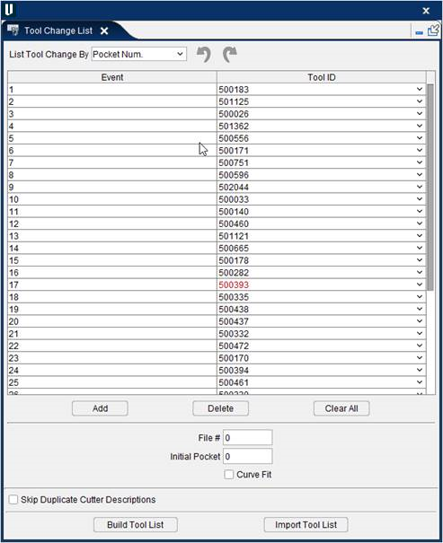
Build Tool List — Builds a tool list by scanning the files in the NC Program list and looking for the tool change events specified by the List Tool Change By feature (see above). When multiple NC program files are listed, a comprehensive tool change events list is created with all tool change activity from all listed NC programs. Sample output is shown in the following image. If there is a tool chain, build tool list action will remove current tools on the chain and sequentially add tool from the NC program to the chain pockets.
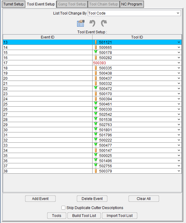
If a Tool ID in the Tool Change List does not exist in the current tool library file, the Tool ID will appear in red text and at the very top of the Tool ID’s pull-down list. This condition can result if the tool library file is changed or if the specific tool has been deleted from tool library file.
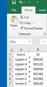
Import Tool List — Similar to the Build Tool List button but with the change that the list that is built here is imported from an existing .csv file that can be selected through the Open Spread Sheet File window. Below is an example of what an imported tool list would look like:
The format for the .csv or Excel file is to have the Event in the first column and the ID in the second column as shown below. In the case of multiple sub system/channel inputs, the format "subsystem name + colon + event number" can be used in the event column as seen below:
Using Tool Lists
Vericut can change tools based on a tool change event list, or "tool list" for short. You can use a tool list to specify the tools to use with sequential tool changes, or to replace tools specified for use in the NC program file. All tool lists contain references that link tool change events to retrieve tools stored in a Tool Library file. Refer to Create a New Tool Library, also in the Project Tree section, for information about defining a library of tools.
Conditions that require using a tool list:
-
Tools manually changed when "program stop" codes are processed. These NC programs typically do not have tool descriptions, or references to IDs, or pocket numbers, except possibly in comments.
-
Tools changed via processing parametric cutter description records in the NC program file, however, descriptions do not reflect true cutter shape.
- Tools changed via processing tool path records that reference tool code or pocket numbers, however, pocket numbers do not match the desired IDs of tools in the Tool Library.
Building a New Tool List
Tool lists can be manually built via adding references to an empty list. However, the Build Tool List feature provides a fast and easy way to automatically build a tool list based on the active List Tool Change By option, and current list of NC program files to simulate. The procedure below uses this method.
To build a tool list:
- If needed, click on the
 (Project Tree) icon in the Toolbar, or click Project tab > Project Tree in the menu ribbon to display the Project Tree.
 - In the Project Tree, specify the NC program files to be simulated in the setup.
- In the Project Tree Configure Tooling menu, choose the List option from the Tool Change By pull-down list*.
- Click on the Tool Change By List button to open the Tool Change List panel.
- In the Tool Change List panel, choose the option from the List Tool Change By pull-down that you want to use to generate the tool list. See Tool Change List panel section of Vericut Help for more information.
-
Toggle on (checked), Skip Duplicate Cutter Descriptions to have Vericut omit subsequent cutter descriptions with the same shape. (Recommended for most APT-CLS NC program files.)
-
Click on the
 in the Tool Change List tab to close the Tool Change List panel.
Add, Modify, or Delete Events in a Tool List
Once a tool list is built, it handles all tool change activity during the simulation. If edits are made to NC program file(s), it may be necessary to edit the tool list. Use the procedures below to add, modify, or delete tool change events in the tool list for proper tool change activity.
To add a tool change event to the tool list:
- If needed, click on the (Project Tree) icon in the Toolbar, or click Project tab > Project Tree in the menu ribbon to display the Project Tree.
- In the Project Tree Configure Tooling menu, choose the List option from the Tool Change By pull-down list.
-
Click on the Tool Change By List button to open the Tool Change List panel.
-
In the Tool Change List panel, click on the Add button below the Event/Tool ID table. A new "blank" tool change event is added.
- In the Event field, left-click then type the exact text corresponding to the new tool change event as it appears in the NC program file.
- Left-click in the Tool ID field then type the tool ID, or select it from the Tool ID pull-down list, to assign the tool to the new event.
- Click on the in the Tool Change List tab to close the Tool Change List panel.
To modify an existing tool change event in the tool list:
- If needed, click on the (Project Tree) icon in the Toolbar, or click Project tab > Project Tree in the menu ribbon to display the Project Tree.
- In the Project Tree Configure Tooling menu, choose the List option from the Tool Change By pull-down list.
-
Click on the Tool Change By List button to open the Tool Change List panel.
-
In the Tool Change List panel, click on the tool change event that is to be modified so that it becomes highlighted.
- Edit the tool change event as required.
- Click on the in the Tool Change List tab to close the Tool Change List panel.
To delete a tool change event from the tool list:
- If needed, click on the (Project Tree) icon in the Toolbar, or click Project tab > Project Tree in the menu ribbon to display the Project Tree.
- In the Project Tree Configure Tooling menu, choose the List option from the Tool Change By pull-down list.
-
Click on the Tool Change By List button to open the Tool Change List panel.
-
In the Tool Change List panel, click on the tool change event that is to be deleted so that it becomes highlighted, then click the Delete button below the Event/Tool ID table. The tool change event is deleted from the list.
Alternatively, you can right-click on the event so that it becomes highlighted and then click on Delete in the menu that displays to delete the tool change event from the list. -
Use the Clear All button to clear all tool change events from the list at one time.
- Click on the in the Tool Change List tab to close the Tool Change List panel.
Turret Setup tab
Location:
Tool Manager Tool Bar > Utilities tab  (Tool Change List > Turret Setup)
The features in the Turret Setup tab enable you to load or change tools, or change tool positions in a turret.
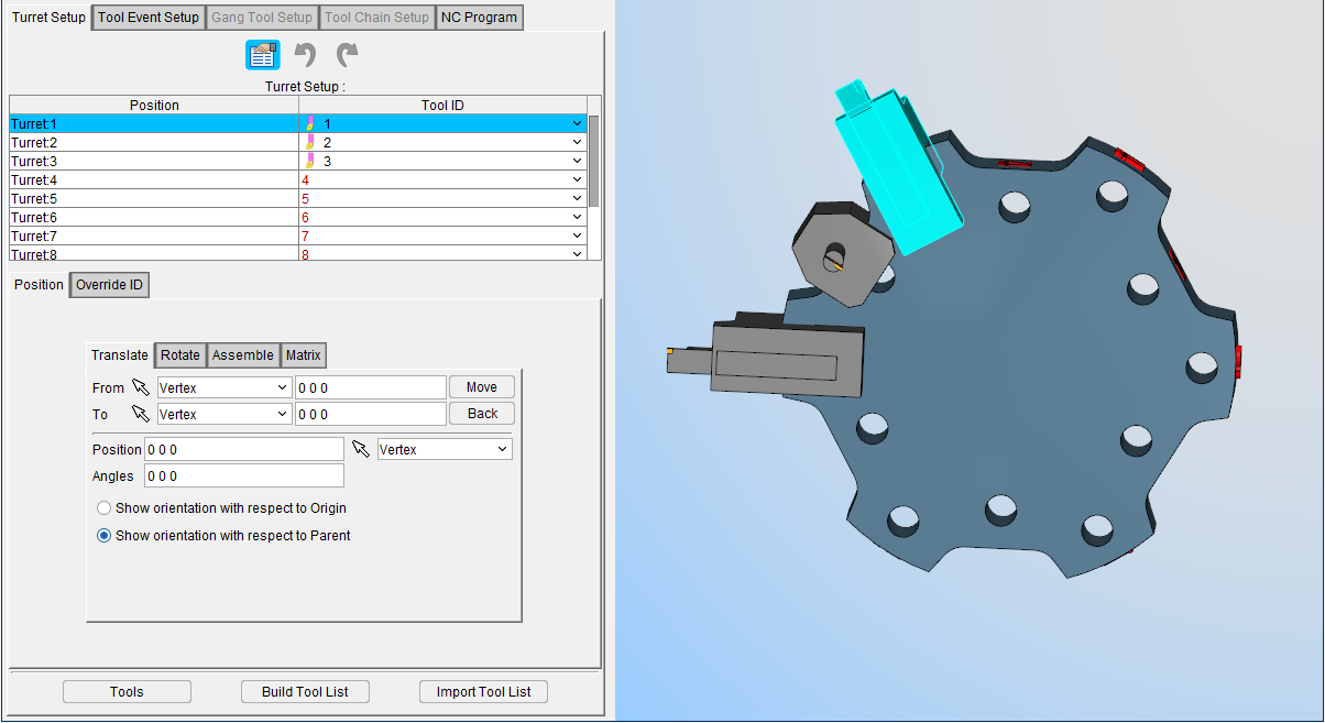
Turret Setup Table
Each record in the Turret Setup Table represents a position on a turret. The table presents information for the Turret Position and for the Tool ID associated with that position. By selecting the Tool ID cell, you can assign a tool to the desired position.
When you select a record in the Turret Setup Table, the record becomes highlighted. The Tool Display area in Tool Manager updates to display the turret with all tools currently loaded in it. The tool represented by the selected record is marked in the turret display as well as becomes highlighted in the Tool Manager Tool Table.
To add or change a tool associated with the highlighted turret record, click in the Tool ID field for that record and select the desired tool from the pull-down list. The list will contain all tools in the current Tool Library and a blank field or select Tool ID in Tool Manager, drag and drop in the table at the desired location.
Position tab
The Turret Setup, Position tab is used to correctly orient a tool (or tool assembly) on a turret, similar to orienting models. The features on the tab work the same as the features on the corresponding tab on the Tool Manager Assembly tab.
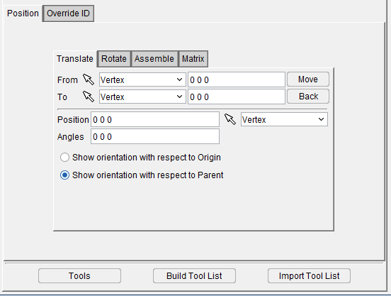
The following features are common to all of the Turret Setup tabs:
Relative CSYS — Use this pulldown menu to select which CSYS to use. Options include Local, Parent, Machine Origin, Active CSYS, and Program_zero. You can toggle on (check) the adjoining Display checkbox to have the CSYS appear in the Graphics Area. The Color Palette icon  next to that checkbox can be used to change the color of the displayed CSYS.
Position — Specifies the absolute XYZ position of the tool component relative to the tool origin. Values in this field are separated by spaces. You can use the mouse icon and the pull down menu from which you can designate which feature to analyze in order to select a position from the Graphics Display Area by clicking on the desired location.
Angles — Specifies the absolute XYZ rotation of the tool component relative to the tool origin. Values in this field are separated by spaces.
Show orientation with respect to — Toggle between showing orientation relative to the origin of the piece or relative to the parent piece.
Transform Menu — The Transform Menu is used to open the Transform Menu window, enabling you to create a transform menu. This feature is explained in depth in the Configure Coordinate System branch menu section of Vericut Help.
Reset — Use this button to undo any and all changes that have been made.
Turret Setup, Translate tab
Features on this tab enable you to translate the selected tool (or tool assembly) via indicating "from" and "to" points to move the tool, similar to translating models. Movement occurs each time you press the Move button. If the applied movement is incorrect, press Undo (in the Turret Positioning window) to return the object to its previous location.
Features on this tab work the same as the Translate tab features on the Tool Definition window: Assembly tab.
Translate tab features:
From / To — Use to specify a "From" point and "To" point that are used to calculate the distance that the tool is to be moved, relative to the tool origin. XYZ values can be entered (separated by spaces), or selected by clicking in the field then clicking on the tool in the Turret Display area. As you move the mouse over the tool, a crosshair and vector show you the pending pick-point location.
Move — Moves the selected object by the incremental distance, as calculated from the "From" point to the "To" point location.
Back — Moves the selected object by the incremental distance, as calculated from the "To" point to the "From" point location.
The remaining features are described in Common Features and Position tab.
Turret Setup, Rotate tab
Features on this tab are used to rotate the selected tool (or tool assembly) about a rotation center point, similar to rotating models. Movement occurs each time you press one of the rotation direction buttons: X+/X-, Y+/Y-, Z+/Z-. If the applied rotation is incorrect, press Undo (in the Turret Positioning window) to return the object to its previous location.
Features on this tab work the same as the Rotate tab features on the Tool Definition window: Assembly tab.
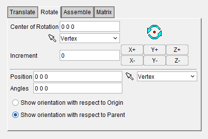 Rotate tab features:
Center of Rotation — Specifies XYZ point location about which to rotate the tool. XYZ values can be entered in the Center of Rotation text field (separated by spaces), or selected by clicking in the Center of Rotation text field, then clicking on a tool in the Turret Display area. To see the center of rotation, press  . To remove the center of rotation symbol press the button again, or close the window. You can use the mouse icon and the pull down menu from which you can designate which feature to analyze in order to select a position from the Graphics Display Area by clicking on the desired location.
Increment — Specifies incremental degrees of rotation to apply when one of the rotation direction buttons are pressed.
Rotation buttons — (X+/X-, Y+/Y-, Z+/Z-) Applies the incremental degrees of rotation specified in the Increment field. Rotation occurs about the Center of Rotation relative to the tool origin.
The remaining features are described in Common Features and Position tab.
Turret Setup, Assemble Tab
The features on this tab enable you to orient a tool (or tool assembly) on a turret, by mating, or aligning, one to three planar surfaces with surfaces on the turret, similar to assembling models. If a non-planar surface is selected, Vericut constructs a tangent plane at the pick point. The relationship of surfaces being mated or aligned is known as a "constraint". If the applied movement is incorrect, press Undo (in the Turret Positioning window) to return the tool to its previous location.
Features on this tab work the same as the Assemble tab features on the Tool Definition window: Assembly tab.
Follow these general steps to define a constraint for assembly:
-
Choose the constraint type.
-
In the Turret Display area, select a surface on the tool to move.
-
Select the surface to move the tool relative to on the turret.
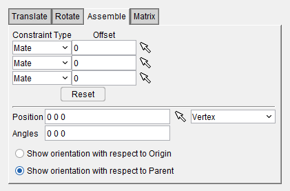
Assemble tab features:
Constraint Type — Specifies how to constrain selected surfaces during tool movement. After selecting two surfaces in the Turret Display area to define a constraint, Vericut moves the tool and highlights the satisfied constraint with a checkmark. Options:
-
Mate — Moves the tool so the selected surface opposes the surface selected on the turret (surface normals oppose each other).
-
Align — Moves the tool so the selected surface is aligned with the surface selected on the turret (surface normal point in the same direction).
-
Offset — Distance and direction in which to offset constrained surfaces, applied normal to the surface.
Reset — Resets constraints to receive new data.
The remaining features are described in Common Features and Position tab.
Turret Setup, Matrix tab
Features on this tab enable you to orient the selected tool (or tool assembly) via a twelve parameter transformation matrix, similar to orienting models with a matrix. If the applied movement is incorrect, press Undo (in the Turret Positioning window) to return the object to its previous location.
Features on this tab work the same as the Matrix tab features on the Tool Definition window: Assembly tab.
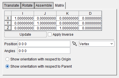
Matrix tab features:
Matrix table — The transformation matrix table is similar to the matrix used in programming APT tool paths. Its twelve parameters reveal the geometric attributes of the local (transformed) coordinate system (CSYS) in terms of the machine origin.
The format of the matrix table is as follows:
📝 NOTE: If you prefer to see the Matrix Table displayed with the I, J, K along the vertical axis and the X, Y, Z along the horizontal axis, set the environment variable, CGTECH_MATRIX_FORMAT=VERTICAL. Update — Updates the tool location to reflect the matrix table transformation.
Apply Inverse — When selected, inverts the matrix so that its twelve parameters reveal the geometrical attributes of the machine origin in terms of the local (transformed) coordinate system.
The remaining features are described in Common Features and Position tab.
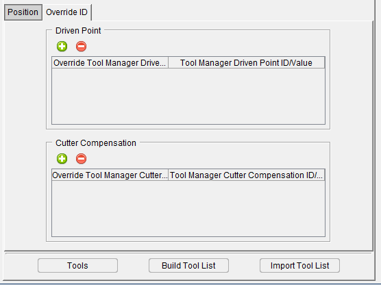
Override ID tab
The features on the Override ID tab are used to alter Driven Point and Cutter Compensation values. Use the green plus icon (![]() ) to add an override to affect previously inserted Driven Point or Cutter Compensation values. Use the red removal icon (
) to add an override to affect previously inserted Driven Point or Cutter Compensation values. Use the red removal icon (![]() ) to delete the override. Enter desired numerical value for Driven Point or Cutter Compensation ID and select from the pull down menu desired value from Tool Manager definition or enter desired numerical value for Driven Point or Cutter Compensation ID manually.
) to delete the override. Enter desired numerical value for Driven Point or Cutter Compensation ID and select from the pull down menu desired value from Tool Manager definition or enter desired numerical value for Driven Point or Cutter Compensation ID manually.
Tool Event Setup tab
Location:
Tool Manager Tool Bar > Utilities tab 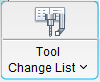 (Tool Change List > Tool Event Setup)
The features in the Tool Event Setup tabenable you to load or change tool events.
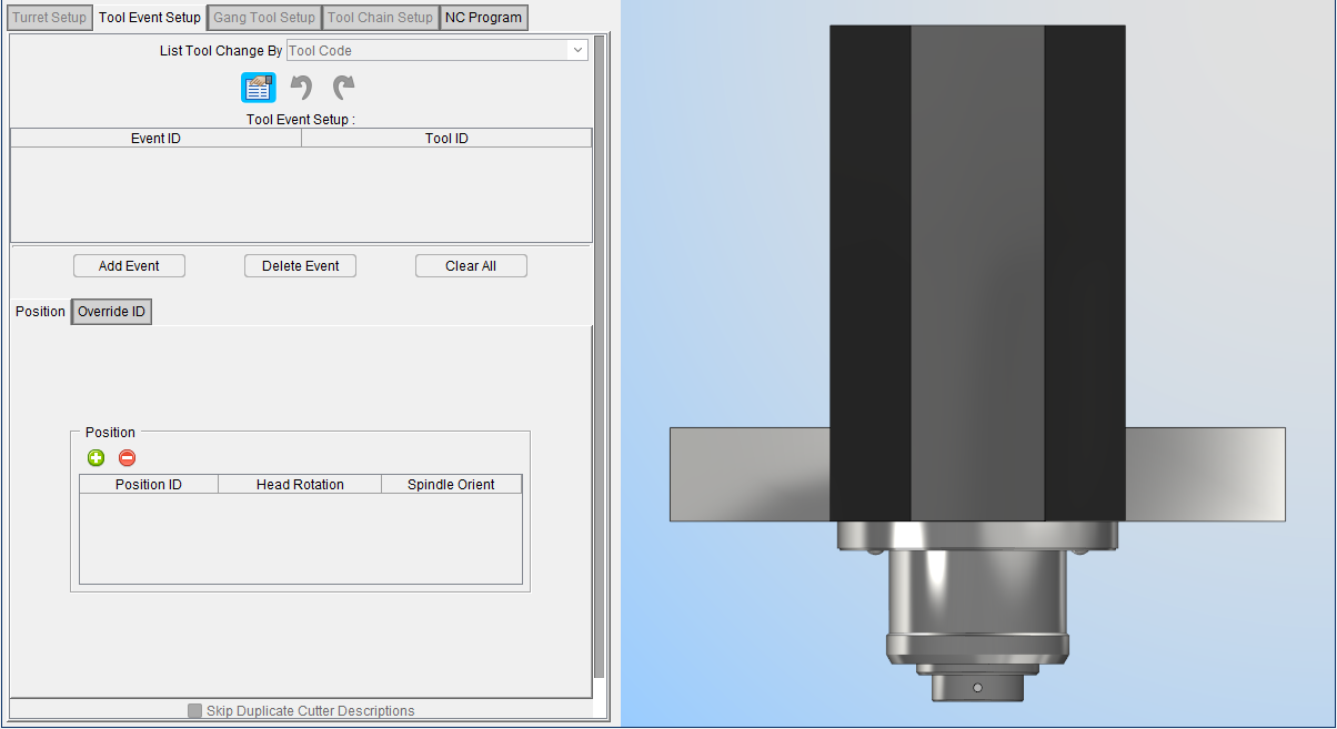
List of tool change events expected to occur during the simulation as indicated by the active List Tool Change By option and IDs of the tools to use for each. Event text must match the tool change record text exactly as it appears in the NC program file. Type or left-click and choose the tool ID from an option list. Right-click to add and delete tool list entries.
The Tool Change List consists of the following columns of information:
List Tool Change By — Use this pulldown feature to select the order in which tools will be displayed. Sort by Cutter Desc., Vericut TC, Tool Code, Prog. Stop, and Tool Code Per File options.
*Event ID — *Displays the tool change event.
Tool ID — Displays the ID of the tool associated with the tool change event or select Tool ID in Tool Manager, drag and drop in the table at the desire location.
Add Event — This feature enables you to add a new tool change Event/Tool ID to the Tool Change List. Select the Tool ID from the Tool ID pull-down list.
Delete Event — This feature enables you to delete the highlighted Event/Tool ID from the Tool Change List.
Clear All — Clears all Event/Tool ID records from the from the Tool Change List.
📝 NOTE: Always reset Vericut (press ![]() (Reset Model) on the Vericut main window) after making changes.
(Reset Model) on the Vericut main window) after making changes.
Position tab — Enables you to control the positioning of the tool. Use the green plus icon (![]() ) to add a new positional entry. Use the red removal icon (
) to add a new positional entry. Use the red removal icon (![]() ) to delete the entry. You can manually edit the Position ID, Head Rotation, and Spindle Orient values by clicking on their respective cells and typing in the desired value. Position can also be set via Offsets: Location when Machine Locations is selected and the Location Name is set to Head Position.
) to delete the entry. You can manually edit the Position ID, Head Rotation, and Spindle Orient values by clicking on their respective cells and typing in the desired value. Position can also be set via Offsets: Location when Machine Locations is selected and the Location Name is set to Head Position.
Override ID tab — Enables you alter Driven Point and Cutter Compensation values. See Override ID tab section for more information.
Skip Duplicate Cutter Descriptions — When toggled on (checked), causes Vericut to skip duplicate cutter descriptions when building the tool change event list. This feature is useful for suppressing redundant tool changes often output by CAM systems for different cutting operations by the same cutter.
Gang Tool Setup tab
Location:
Tool Manager Tool Bar > Utilities tab  (Tool Change List > Gang Tool Setup)
The features in the Gang Tool Setup tabenable you to load or change tools, or change tool positions on a gang tool.
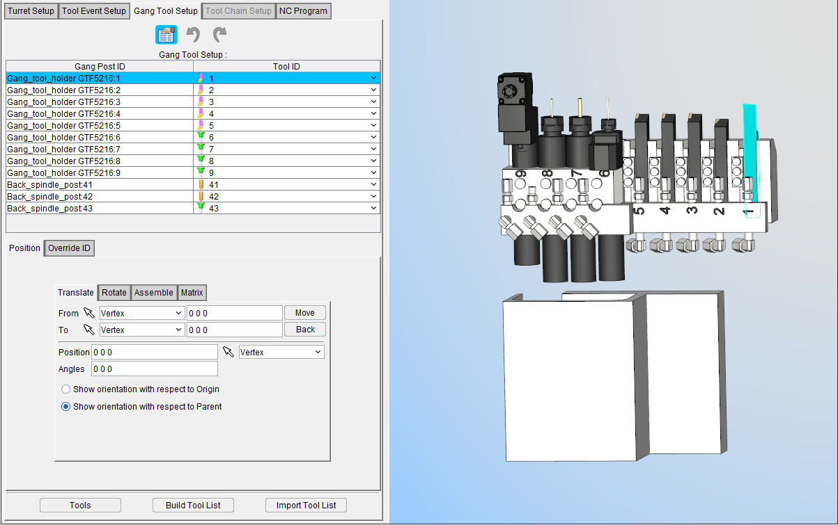
The features on this window work identically to the features on Turret Setup Position tab and Override ID tab features.
Tool Chain Setup tab
Location:
Tool Manager Tool Bar > Utilities tab  (Tool Change List > Tool Chain Setup)
The features in the Tool Chain Setup tab enable you to load or change tools, or change tool positions in a tool chain.
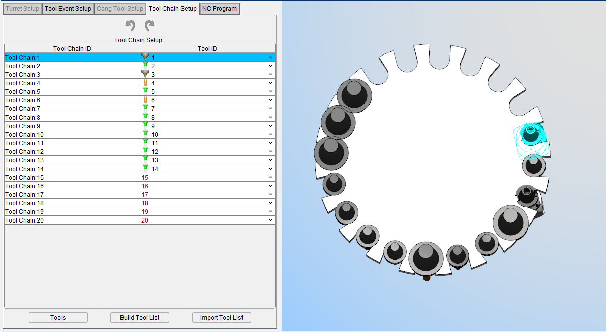
The table presents information for the Turret Position and for the Tool ID associated with that position. By selecting the Tool ID cell, you can assign a tool to the desired position.
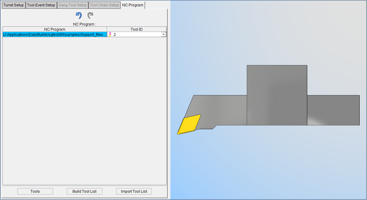
NC Program tab
Location:
Tool Manager Tool Bar > Utilities tab  (Tool Change List > NC Program)
The features in the NC Program tabenable you to assign Tool IDs to already loaded NC Programs.
Changing Tools by NC Program File Names
Use the procedure below to have Vericut change tools based on NC program file names.
📝 NOTE: This option requires using a Tool Library. See "Create a New Tool Library", also in the Using Vericut section, for information about defining a library of tools referenced by tool changes.
To change tools with tool path file names:
- If needed, click on the
 (Project Tree) icon in the Toolbar, or click Project tab > Project Tree in the menu ribbon to display the Project Tree.
 - In the Project Tree, specify the NC program files to be simulated in the setup.
- In the Project Tree Configure Tooling menu, choose the File Name option from the Tool Change By pull-down list.
-
Click on the Tool Change By File button to open the Tool Change by File Name panel. The Tool Change by File Name panel will display with a record for each NC program listed for the setup.
-
In the Tool Change by File Name panel, click on the first NC program in the list so that it becomes highlighted.
- Click in the Tool ID column and then select the tool ID of the tool that is to be used for cutting the highlighted NC program.
- Repeat Step 6 for every NC program in the list.
- Click on the
 in the Tool Change List tab to close the Tool Change by File Name panel.