Settings (Settings window)
Location:
Project tab >  (Settings)
📝 NOTE: The image that is displayed in the top of the Settings icon and the Quick Access Toolbar short cut will change depending on which Settings panel (Properties, Output Files, G-Code Advanced Settings, G-Code Outputs, APT Settings, or Auto Save) was last displayed.
The Settings command button displays the Settings window. The features on the Settings window enable you to:
-
set properties for the verification session, such as: cut mode, resolution and tolerance values that affect cut model display, accuracy, and motion simulation.
-
setup, create, or view Vericut's many output files.
- configure the settings required to support processing of G-Code NC program files.
- specify "Machine Locations" to store work offsets and machine locations specific to the current NC program file(s) and "Tool Offsets" to store tool-related offset and cutter compensation data. Control which levels of block skipping are recognized, and specify the block skip character. Select which Channel SubSystem is to be used. Configure Vericut for wire EDM simulations.
- configure the settings required to support the processing of APT-CLS NC program files.
- configure Vericut to automatically save In Process files, View Capture image files (such as JPEG, PS, EPSF, or TIFF files), or Vericut Solid (.vct) files.
Properties tab — The features on the Properties tab enable you to set properties for the verification session, such as: cut mode, resolution and tolerance values that affect cut model display, accuracy, and motion simulation.
Output Files tab — The features on the Output Files tab enable you to setup, create, or view Vericut's many output files.
G-Code Outputs tab — The features on the G-Code Outputs tab enable you to configure the settings required to support processing of G-Code NC program files.
G-Code Advanced tab — The features on the G-Code Advanced tab enable you to specify "Machine Locations" to store work offsets and machine locations specific to the current NC program file(s) and "Tool Offsets" to store tool-related offset and cutter compensation data. Control which levels of block skipping are recognized, and specify the block skip character. Select which Channel SubSystem is to be used. Configure Vericut for wire EDM simulations.
Apt Settings tab — The features on the APT Settings window enable you to configure the settings required to support the processing of APT-CLS NC program files.
Auto Save tab — The features on the Auto Save tab enable you to configure Vericut to automatically save In Process files, View Capture image files (such as JPEG, PS, EPSF, or TIFF files), or Vericut Solid (.vct) files. Saving is based on user specified events or when Vericut detects errors during NC program processing. Auto-saving is especially useful to save data during batch processing.
OK — Saves the tab settings and closes the Settings window.
Apply — Saves the current tab settings and leaves the Settings window open.
Cancel — Closes the Settings window without saving changes.
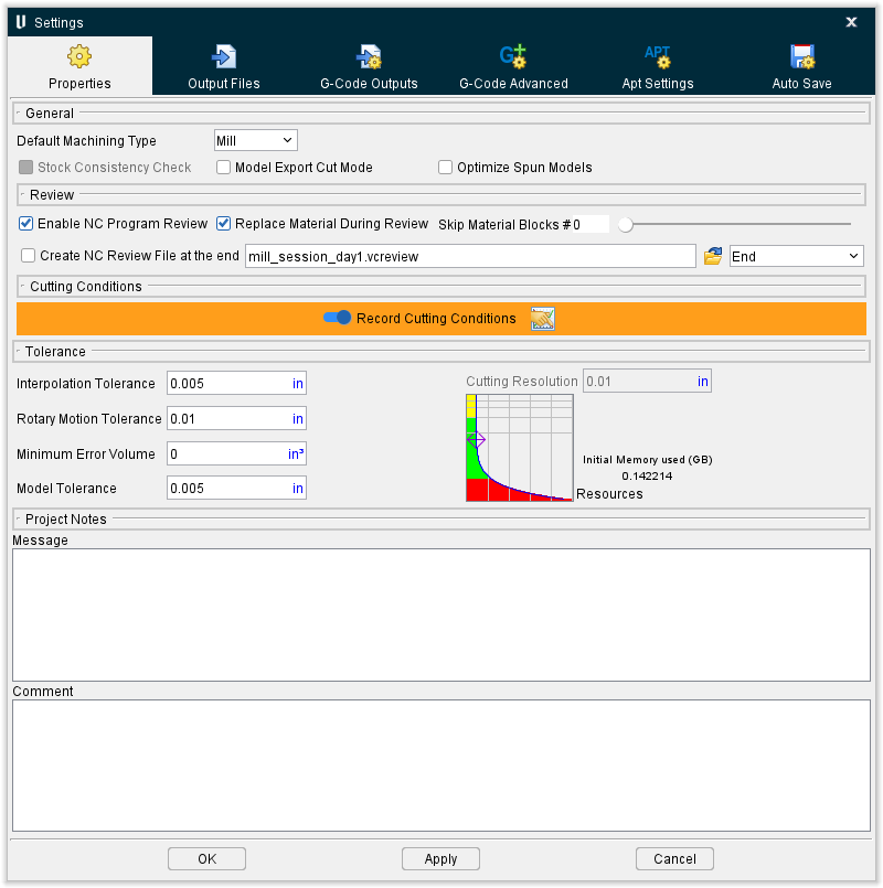
Settings window, Properties tab
The features on the Settings window, Properties tab enable you to set properties for the verification session, such as: cut mode, resolution and tolerance values that affect cut model display, accuracy, and motion simulation. It also enables you to activate, or inactivate, NC Program Review and to add notes to the project file.

General
The features in the General group of the Properties tab establish general properties for the Vericut simulation session.
Default Machining Type — Sets the machining mode for Vericut. Options:
-
Mill — A spinning tool removes material when in contact with Stock/Fixture.
-
Turn — A Spindle spins the Stock/Fixture assembly and a stationary tool (not spinning) removes material when in contact with Stock/Fixture.
-
Wire EDM — An electrically charged wire removes material when in contact with Stock/Fixture.
-
Additive — An additive tool deposits additive beads to build up new material to a base when in contact with a Stock/Fixture. When selected, Vericut bases Cutting Resolution calculations on all Stock+Design models combined, even those that are not visible. This enables Vericut to predict system resources that will be needed to additively build the as-designed part, including an starting stock build plate or model.
Stock Consistency Check — When toggled "on"(checked), Vericut checks the consistency of stock models, including: check for "watertight" solid- repair improperly trimmed surfaces (overlaps and gaps), and reconstruct insignificant missing surfaces. This option is highly recommended for stock models creating from importing IGES data, and other model files where portions of the stock model disappear, or gaps/seams appear in the model when cutting is started.
Model Export Cut Mode — When toggled "on"(checked), causes Vericut to cut with a more accurate internal cutter representation for better results when using modules like Model Export or Optimization. Only toggle "on" when the additional accuracy is required as it can have an impact on processing speed.
Optimize Spun Models — When toggled "on" (checked), this feature is used to produce more accurate geometric representations of spun machine models and milling tools. In turning operations, these are the models attached to a turning spindle. In milling operations, this option can be used to create spun geometry of cutters/holders of milling tools when they are comprised of STL models.
Enable NC Program Review — When toggled "on" (checked), the icons and menu options that provide access to NC Program Review are activated and the data needed by NC Program Review is stored in memory. When toggled "off" (not checked), the icons and menu options that provide access to NC Program Review are inactivated (grayed out). With NC Program Review toggled "off" the amount of memory that Vericut uses is greatly reduced since it does not need to store the data that is needed by NC Program Review.
Replace Material During Review — When toggled "on" (checked), removed material will be replaced as you step back through the NC program. This feature can be turned on at any point in the simulation but Vericut will not start to store the information required to replace material while stepping back until Replace Material During Review is toggled "on". Cuts made prior to turning this feature on will not replace material while stepping back. Vericut will store up to 1000 cut records that remove material.
Skip Material Blocks — Use this field to manually enter the number of blocks you wish to skip. You can also use the adjoining slide bar to set the number.
Create NC Review File at the end — When toggled on (checked), Vericut creates an NC Review File at the end of simulations. Use the text field to the right to specify where the file should be saved.
End dropdown — Use this dropdown menu to select where each file should save: either at the absolute End of the file or at the End of each Setup.
Cutting Conditions
Record Cutting Conditions — When toggled "on" (checked), Vericut saves cutting conditions for each NC block in a temporary file and displays cutting condition values in the Status window without Optimization turned on. This feature is only valid for jobs that could normally be optimized using Optimization.
The Record Cutting Conditions feature must be turned on before Vericut will begin to save the cutting conditions for each block to a temporary file. When the Record Cutting Conditions feature is toggled "off" the cutting conditions data accumulated to the current point are removed from the temporary file.
See Status panel, in the Info tab section of Vericut Help for additional information.
![]() — Opens the Preferences window, Graphs tab.
— Opens the Preferences window, Graphs tab.
Tolerance
The features in the Tolerance group of the Properties tab enable you to set tolerances for the simulation. The tolerance values control the accuracy of the cut stock model, simulated circular motion and other interpolated motions, whether or not certain errors get written to the error log, and the accuracy of cylinders, cones and other revolved models and tool assemblies for collision checking.
Interpolation Tolerance — This value is used to interpolate intermediate positions during NURBS, circular, and helical motions. This tolerance is also used by the Detect 4-Axis Rotary Motion APT setting to determine if sequential GOTO locations can be performed as a single 4-axis motion- ref. Project tab > Settings dropdown menu > APT Settings: Rotary tab.
Rotary Motion Tolerance — The Rotary Motion Tolerance value is used with the max tessellation angle to calculate intermediate tool positions resulting from processing rotary motion. Decreasing this value increases the number of intermediate points calculated and enables Vericut to do a better job of collision detection. Tightening up this tolerance value will not significantly affect performance. This tolerance value also applies to rapid rotary motions.
📝 NOTE: The Rotary Motion Tolerance is designed to keep the tool tip within tolerance when breaking up a rotary move. The max tessellation angle (specified using the MaxTesselationAngle macro) is a better setting to use with collision detection. The number of intermediate points will be based on the maximum of these two calculation methods.
Minimum Error Volume — This value sets a threshold for the minimum volume of material that must be removed by a fast feed motion or holder collision in order for an error to be reported. If the volume removed by an error motion is less than this value then no error is reported in the log file or logger for the motion and the error count is not incremented.
However, any volume of material removed by a fast feed motion or holder is always shaded in the error color (typically red), regardless of the volume. Thus small volume errors may be shaded red but will not be reported in the log file or logger if the volume is less than Minimum Error Volume value. The Minimum Error Volume value is in cubic units (inch or millimeter).
Examples
-
If a value of 0.0005 cubic inches is entered for Minimum Error Volume, then the potential length of a side of the cube representing the volume is 0.0793 inch (the cube root of 0.0005 cubic in. is 0.0793 in.).
-
If a value of 0.008 cubic mm is entered for Minimum Error Volume, then the potential length of a side of the cube representing the volume is .2 mm (the cube root of .008 cubic mm. is .2 mm.).
Use this setting to filter very small fast feed and holder collisions from Vericut's error reports. The default value "0" causes Vericut to report all fast feed and holder/stock collision errors.
Model Tolerance — This value is used when displaying revolved models such as cylinders, cones, and revolved profiles in Vericut and used when displaying revolved profiles and revolved cutters in Tool Manager. It is also used when displaying the revolved image of a turning stock model created from an IGES profile. The accuracy of cylindrical tool assemblies, displayed in a machine view, is also affected by this value.
This value has a small effect on collision checking accuracy for revolved models used to represent machine components or fixtures.
This value is also used for the chordal deviation tolerance when a STEP model file is converted into triangles as it is being loaded into Vericut. This value is also used when Importing CAD Models into Vericut or Tool Manager to control testalation/chordal deviation tolerance.
📝 NOTE: Tool Manager has its own Model Tolerance type settings for CAD Tool Import which can be controlled through Tool Manager Preferences, Imported CAD Model Options.
Cutting Resolution — This value sets the accuracy of Vericut's cut stock model. Increasing the Cutting Resolution value increases the speed of the simulation and various other operations, and uses less memory, but reduces the accuracy of the cut stock model. Decreasing the value improves accuracy of the cut stock model, but reduces speed and increases the memory required by the cut stock model.
The Cutting Resolution affects the accuracy and speed of AUTO-DIFF, Model Export, and Optimization. A smaller Cutting Resolution value produces more accurate results but takes longer to process. Vericut's ability to detect small holder collisions and fast feed errors are also affected. The speed of dynamic rotate/pan/zoom operations and the time required to create the refined image in the workpiece view are also affected.
Vericut applies the Cutting Resolution value directly, creating the cut stock model at the specified accuracy. The tool path files are not scanned to detect the cutters used. The value represents the size of the smallest cut feature Vericut can detect.
📝 NOTE: It is very important to understand that the value represents the size of a cut's volume measured in any direction. Thus, cuts that are larger than the Cutting Resolution value in at least one direction will be detected by Vericut.
For example, a .001" axial depth cut by a .25" ball end mill produces a volume with the following shape:
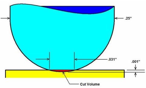
As a general practice, setting Cut Tolerance to one-fourth (¼) the size of a cut volume's span will detect the cut. Thus in this case, to detect a .001" deep cut by a .25" ball end-mill, set Cut Tolerance to .007" or smaller. However, results can vary depending on the shape of the cut volume.
📝 NOTE: This feature is only available when the first setup in a project is active. For subsequent setups, this feature is grayed out.
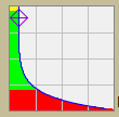
The Cutting Resolution Graph, shown in the picture below, provides a graphical way to determine an appropriate Cut Tolerance value.
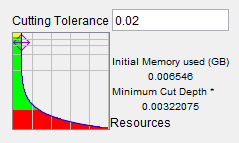
You can set the Cut Tolerance value either by dragging the diamond marker on the graph or by entering a value in the Cut Tolerance text field.
The green zone in the graph defines the workable region for the cut tolerance of the current project. The top of green is a constant. It’s cut tolerance = 0.025 for an inch project file or 0.635 for a millimeter project file. This defines the maximum cut tolerance you need for relatively reasonable accuracy for material removal. The bottom of the green zone is the turning point of the shape of the curve that indicates that a cut tolerance value smaller than that will result in significant increases in the amount of resources (time and memory) required. The value at the bottom if the green section is a percentage of the available of memory. For a computer with 11G memory, it is about 2G of memory.
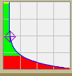
Although the shape of the curve is almost constant (does not change), its green zone area can change dramatically based on stock size. The followings are three different graphs illustrating small, medium, large size of stocks:
| Small Size Stock | Medium Size Stock | Large Size Stock |
|---|---|---|
 |
 |
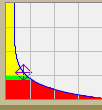 |
The purpose of the graph is to give you a guide line to which cut tolerance region (green zone) you should work with. Cut tolerance values in the red zone should be avoided and cut tolerances values in yellow zone indicate that the cut tolerance values will not provide enough accuracy. The graph should not be interpreted as an exact relationship between cut stock and performance.
The Base Cut Tolerance on, Tool Size option in previous releases has been removed. For pre-V7.4 projects that use the cut tolerance based on tool size option, the tool based tolerance is converted to a stock based tolerance. The conversion happens either the first time you open the Settings window, or the first time the Play or Step button is used. The project will be marked as changed and you will be prompted to save the project when you exist.
Project Notes
The features in the Project Notes group of the Properties tab enable you to add Message Notes and Comment Notes to the header of a Project file.
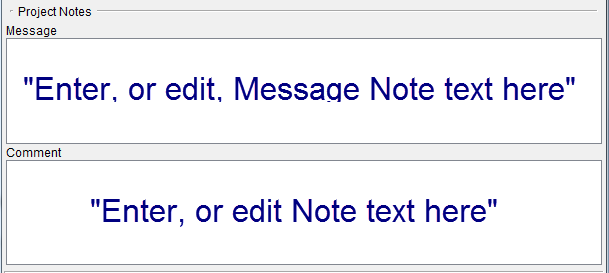
Message Notes are saved in the header of the project file and are displayed in the Vericut message area (Logger) when the project file is loaded.
Comment Notes are saved in the header of the project file but do not display in the Vericut Logger.
There is a limit of 255 characters per line, but there is no limit to the number of lines that can be added.
Any Message/Comment Notes that currently exist in the control file are displayed in the appropriate text field as shown below. Any note can be edited and re-saved in the project file.
Existing Message/Comment Notes in the Project file:
In the Project file, each line of the note is added to the header in quotes, and is preceded by either the keyword MESSAGE (for message notes), or COMMENT (for comment notes) as shown below.
How the above message looks in the Project file:
`Vericut Machine`

`Version-<version number>`

`MESSAGE "This is the 1st Message Note added to the project file and it will appear in the logger."`

`MESSAGE "This is the 2nd Message Note added to the project file and it will appear in the logger."`

`COMMENT "This is the 1st Comment Note added to the project file and it will not appear in the logger."`

`UNITS MILLIMETER`

`MACHINE "" {`

`PRIORITY_TYPE SINGLE`
Adding /editing notes:
Add a note by typing the desired text, or edit the text of existing notes in the appropriate text field. When finished, press OK, or Apply, depending on whether or not you want to leave the Machine Settings window open. Then save the project file using the File tab > Save Project (or Save As) feature in the menu ribbon, or use the ![]() (Save Project) or
(Save Project) or ![]() (Save Project As) icon in the tool bar.
(Save Project As) icon in the tool bar.
Settings window, Output Files tab
The features on the Settings window, Output Files tab enable you to specify, View, and adjust settings for Vericut output files (Log file and Optimization file).
💡 Tip: You can also access the Settings window, Output Files tab by selecting Project tab > Settings dropdown menu > Output Files.
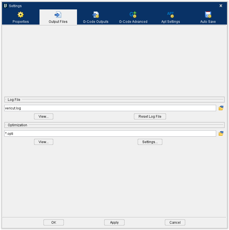
Log File — Use to specify the name of the Vericut Log file. Enter the \path*filename* in the Log File text field, or click on the  (Browse) icon and use the Save File file selection window that displays to specify the \path*filename*.
View — Opens a window containing the Vericut Log file. This file contains session information, such as error, warning and informational messages about the verification session. Standard text editing features are provided, such as: copy/cut, paste, search, etc. For more information on using the editing features, see Text File under Machine/Control tab.
Reset Log File — Use to clear the contents of the Vericut Log file.
Optimization — Use to specify the name of the Optimized file. Enter the \path*filename* in the Optimization text field, or click on the (Browse) icon and use the Save File file selection window that displays to specify the \path*filename*.
View — Opens a window containing the optimized NC program file. Standard text editing features are provided, such as: copy/cut, paste, search, etc. For more information on using the editing features, see Text File under Machine/Control tab.
Settings — Displays the Optimize Control window.
Settings window, G-Code Outputs tab
The features on the G-Code Outputs tab enable you to configure the settings required to support processing of G-Code NC program files.
💡 Tip: You can also access the Settings window, G-Code Outputs tab by selecting Project tab, G-Code Outputs.
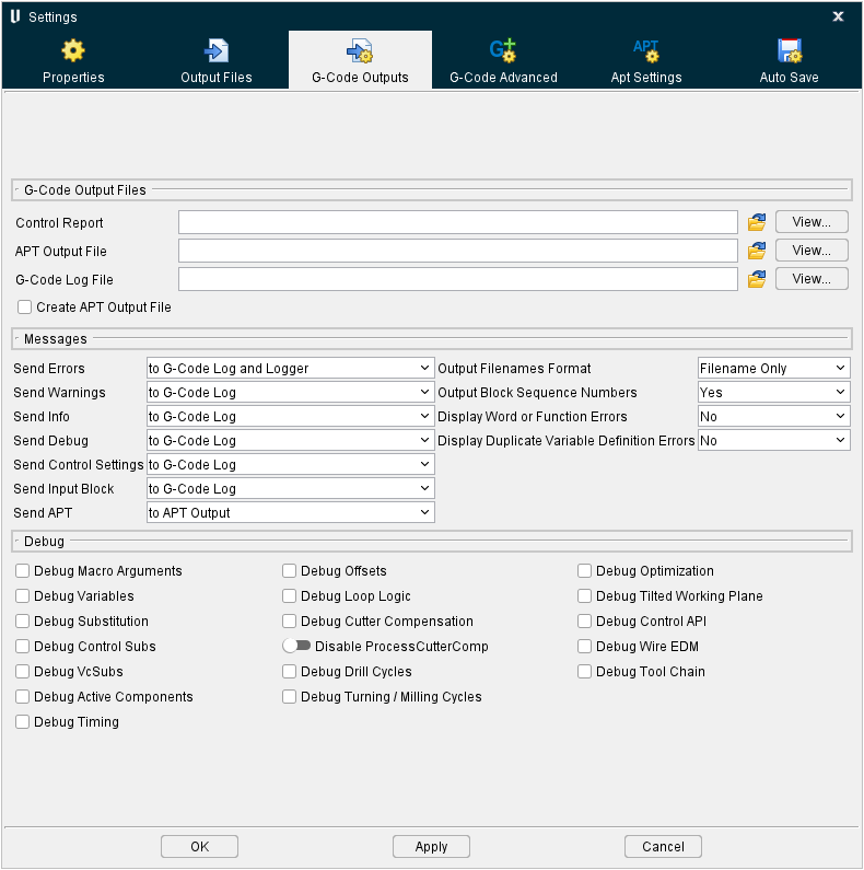
G-Code Output Files
The features on the G-Code Output Files group of the G-Code Outputs tab enable you to configure the settings required to support processing of G-Code NC program files.
Control Report — Use to specify a name for the Control Report to be created. Enter the \path*filename* in the Control Report text field, or click on the  (Browse) icon and use the Save File file selection window that displays to specify the \path*filename*. This file contains information about how the current NC control configuration will interpret various codes.
View — Opens the Control Report window containing the Control Report file. In this window, you can view, edit, or reset the Control Report file contents.
The Control Report window enables you to view, edit, or reset the contents of a Control Report file.
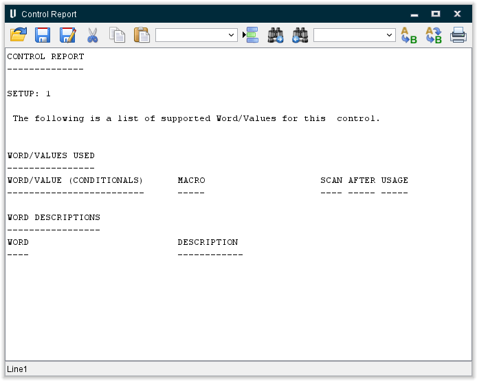
The Tool Bar provides standard text editing features such as: copy/cut, paste, search, etc. Moving the cursor over the icon will display name of the option. For more information on using the editing features, see Text File in the Utilities tab section of Vericut Help.
APT Output File — Name of the file to receive ASCII APT NC program records resulting when the Create APT Output File feature is active (see below). Enter the /path/filename of the file in the APT Output File text field or click on the (Browse) icon to display the Select Output File file selection window and use it to specify the /path/filename. If left blank the file will not be created.
View — Opens the APT Output File window displaying the APT Output file containing the ASCII APT NC program records created when the Create APT Output File feature is active (see below).
The APT Output window enables you to view, edit, or reset the contents of an APT Output file.
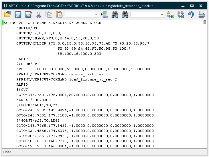
The Tool Bar provides standard text editing features such as: copy/cut, paste, search, etc. Moving the cursor over the icon will display name of the option. For more information on using the editing features, see Text File in the Utilities tab section of Vericut Help.
G-Code Log File — Name of the file to receive error, warning and informational messages about G-Code processing. Enter the /path/filename of the file in the G-Code Log File text field or click on the (Browse) icon to display the Select Log File file selection window and use it to specify the /path/filename. If left blank the file will not be created.
View — Opens the G-Code Log window displaying the G-Code Log file. This file contains information, such as error, warning and informational messages about G-Code processing.
Create APT Output File — When active, converts the G-Code NC Program data into ASCII APT NC Program records. Converted data is stored in the specified APT Output file (see above).
For information about APT NC program records and formats, see "Supported APT-CLS records".
Messages
The features on the Messages group of the G-Code Outputs tab enable you to set the destination and format of messages output during a simulation.
Messages can be sent to the destinations listed below:
- to Nowhere (not available for Send Error Messages, Send Warning Messages or Send Output Messages)
-
to G-Code Log (not available for Send Output Messages)
-
to APT Output
- to APT Output and G-Code Log
- to Logger (not available for Send Output Messages)
- to G-Code Log and Logger (not available for Send Output Messages)
- to APT Output and Logger
- to APT Output, G-Code Log and Logger
📝 NOTE: Not all destination choices are available for all message types.
Send Errors — Destination of messages about errors-potentially severe problems that will most likely produce incorrect results on the machine tool.
Send Warnings — Destination of messages about possible problems. Scrutinize warnings to decide if they will actually impact the machining process.
Send Info — Destination of messages providing information about files used, the time and date that the process started, etc.
Send Debug — Destination of debug messages providing additional information related to internal calculations, conditions, and variable values. The types of debug messages which appear are controlled via the features in the Debug group of the G-Code Outputs tab.
Send Control Settings — Destination of messages showing the control settings in effect when the tool path file was processed.
Send Input Block — Destination of messages showing the input NC program file records processed.
Send Apt — Destination of messages showing the converted NC program records resulting from reverse-post processing. When Create APT Output File is active on the Settings window: G-Code Outputs tab, output messages are sent to the APT Output File specified on the same window. By default, these records are in ASCII APT format. However, using the C Macro Extension – Application Programming Interface, or CME–API (ref. CME-API Help in the Vericut Development Tools section, in the Vericut Help Library), other output file formats are obtainable.
Output Filenames Format — Controls how names of files used by Vericut are shown. Options:
-
Filename Only
-
Full Path Names — includes full folder path.
Output Block Sequence Numbers — Controls when block sequence numbers are included with APT output records resulting from conversion. The sequence numbers appear in columns 73-80, and are useful for general reference or debugging purposes. Options:
-
Yes — output block sequence numbers
-
No — do not output block sequence numbers
Display Word or Function Errors — Use to specify whether to display Word, or Function, errors. Options:
-
Yes — output Word or Function errors
-
No — do not output Word or Function errors
Display Duplicate Variable Definition Errors — Use to specify whether to display duplicate variable definition errors. Options:
-
Yes — output duplicate variable definition errors
-
No — do not output duplicate variable definition errors
Debug
The features on the Debug group of the G-Code Outputs tab enable you to select what debug messages to send to output. Debug messages can provide additional information that may be helpful debugging development of files used to simulate G-Code NC programs and simulate machine tool motions. Set each Debug Message to either Yes (send to output) or No (don't send to output). The output destination for debug messages is controlled by the "Send Debug Messages" in the Messages group of the G-Code Outputs tab.
Debug Macro Arguments — When toggled on (checked), outputs the macro name, the word, the text string value, and the numeric value for the macro being called.
Debug Variables — When toggled on (checked), outputs debug messages about changes to variable values. See also: Project tab > G-Code Variables (Variables panel).
Debug Substitution — When to set to "Yes", outputs debug messages related to string substitutions (ref. Machine/Control tab > Control Advanced Options: Substitute tab).
Debug Control Subs — When toggled on (checked), all machine and control subroutines are treated like project subroutines. Vericut outputs debug messages associated with machine and control subroutines.
Debug VcSubs — When toggled on (checked), all VcSubs are treated like project subroutines. When checked, Vericut will output debug messages for VcSubs. If “Debug VcSubs” is checked, “Debug Control Subs” must also be checked.
Debug Active Components — When toggled on (checked), the Active Subsystem, Active Tool Component name, and Active Stock Component name will be printed on each block. Also, the Active Spindle Component name will be printed whenever it is used or set.
Debug Timing — When toggled on (checked), time related debug messages [Delta time (time for this block), Total time, and Time Attributes (information used to calculate Delta time)] are output for each block.
There are also 2 debugging statements to assist in debugging sync logic. These messages are:
Debug: Time associated with new Motion/Dwell = 0.09

Debug: Time remaining for motion on Channel 0 = 0.09
Example:
Looking at the start of the millturn_merge_vtl_4ax_gl.vcproject from samples:

On block N25, we have a retract, a tool change, and then a motion

The first motion takes .09 minutes, and the second motion takes .045 minutes

On block O50, we have a retract, a tool change, and then a motion

The first motion takes .05 minutes, and the second motion takes .037 minutes

At the end of block O50, we have .003 minutes left on the first motion from block N25, and .045 minutes left from the second motion.

The total time processed up to this point is .087.
The resulting debugging statements are included:
Input Channel: 1

N25 G0G95G96X-7.5Z.1F.0122S550T4D4M6

  Debug: Time Attributes: RAPID

  Debug: Time associated with new Motion/Dwell = 0.09

  Debug: Time Attributes: RAPID

  Debug: Time associated with new Motion/Dwell = 0.045

  Debug: Time remaining for motion on Channel 0 = 0.09

  Debug: Time remaining for motion on Channel 0 = 0.045

  Debug: Total time = 0

    Input Channel: 2

    O40 G0G95G96U7.5W.1F0.012S550T1D1M3M6M41

      Debug: Time Attributes: RAPID

      Debug: Time associated with new Motion/Dwell = 0.05

      Debug: Time Attributes: RAPID

      Debug: Time associated with new Motion/Dwell = 0.037

      Debug: Time remaining for motion on Channel 0 = 0.003

      Debug: Time remaining for motion on Channel 0 = 0.045

      Debug: Total time = 0.087
Debug Offsets — When toggled on (checked), outputs debug messages about offset value changes, including: coordinate system offsets/shifts, compensation values in use, etc.
Debug Loop Logic — When toggled on (checked), outputs debug messages about values calculated by looping or branching logic.
Debug Cutter Compensation — When toggled on (checked), outputs debug messages about CDC tool offset positions.
Debug Drill Cycles — When toggled on (checked), outputs debug messages about drilling cycles.
Debug Turning/Milling Cycles — When toggled on (checked), outputs debug messages associated with turning and milling cycles, for example the distance from the turning axis to the tool control point and calculations related to the use of constant surface speed.
Debug Optimization — When toggled on (checked), a descriptive message will be printed whenever machine simulation determines a block is non-optimizable.
Debug Tilted Working Plane — When toggled on (checked), outputs debug messages associated with tilted working planes.
Debug Control API — When toggled on (checked), debug messages related to the API Interface for the Heidenhain iTNC Controller are output.
Debug Wire EDM — When toggled on (checked), outputs debug messages associated with wire EDM machining.
Debug Tool Chain — When toggled on (checked), outputs debug messages associated with Tool Chain operation.
Reverse Postprocessing G-Codes to ASCII APT
Use the procedure below to convert, or "reverse post process" G-Code data into ASCII APT NC program records.
To convert (reverse postprocess) G-Codes to an ASCII APT tool path:
- Assuming Vericut is configured to process a G-Code NC program, click on Project tab > Settings to display the Settings window.
-
Click on the G-Code Outputs tab (you can also use the
 (G-Code Output Options) icon in the Toolbar to display the Settings window: G-Code Outputs tab).
 -
Type the /path/filename in the APT Output File text field, or use the
 ()Browse) icon and use the file selection window that displays to select the file to receive converted NC program records.
 - If desired, type the /path/filename in the G-Code Log File text field, or use the (Browse) icon and use the file selection window that displays to select the file to receive error, warning and informational messages about G-Code processing. (Recommended during development of reverse postprocessors.)
- Ensure that the Create APT Output File feature is toggled on (checked).
- Press OK to apply your settings and close the Process Options window. Press Apply to apply your settings and leave the Process Options window open for additional work.
- Press
 (Reset Model) to reset Vericut (to ensure changes take effect) and then press
  (Play) to start the simulation.
 - The conversion occurs during NC program processing. After cutting, review the created files in the Settings window: G-Code Outputs tab.
Select View next to the APT Output File feature to review the APT Output File containing the ASCII Apt NC program records that were just created.
Select View next to the G-Code Log File feature to review the G-Code Log file containing error, warning and informational messages about the G-Code processing.
For information about APT NC program records and formats, see Supported APT-CLS records.
Notes on Reverse Postprocessing
Vericut uses the control configuration for reading/understanding/processing an input G-code/MCD file.
This turns specific G-code/MCD blocks into internal generic motions.
Vericut then positions and removes material via the internal generic motions.
The internal Vericut Reverse Postprocessing (RevPost2) feature outputs generic APT based statements only, having nothing to do with the input G-code/MCD and/or CTL configuration.
The APT industry standards for RAPID and GOTO statements allow input Rapid/G00 and Linear/G01 motions output via the Reverse Postprocessing (RevPost2) feature to "just work" with most postprocessors.
There are basically no APT industry standards for CYCLE statements, as they are typically postprocessor specific.
Thus the Vericut Reverse Postprocessing (RevPost2) feature outputs generic CYCLE statements that will probably not work with most postprocessors.
There is currently no configuration ability for the APT statements that the Vericut Reverse Postprocessing (RevPost2) feature outputs.
The features on the Settings window: APT Settings tab (Project tab > Settings) are used to specify how Vericut is to interpret reading/understanding/processing an input APT file, having nothing to do with CTL configuration or G-Code/MCD input or RevPost2 output.
The Cycle Set and Cycle Definitions features on the Settings window: APT Settings tab enable you to specify how Vericut is to configure and understand most any APT CYCLE statements from most any postprocessor.
Vericut uses the settings on the Settings window: APT Settings tab to interpret the reading/understanding/processing of an input APT file.
This turns specific APT statements into internal generic motions.
Settings window, G-Code Advanced tab
The features on the G-Code Advanced tab enable you to specify “Machine Locations” to store work offsets and machine locations specific to the current NC program file(s) and “Tool Offsets” to store tool-related offset and cutter compensation data, control which levels of block skipping are recognized, and specify the block skip character. Select which Channel SubSystem is to be used.
💡 Tip: You can also access the Settings window, G-Code Advanced tab by selecting Project tab > G-Code Advanced Settings.
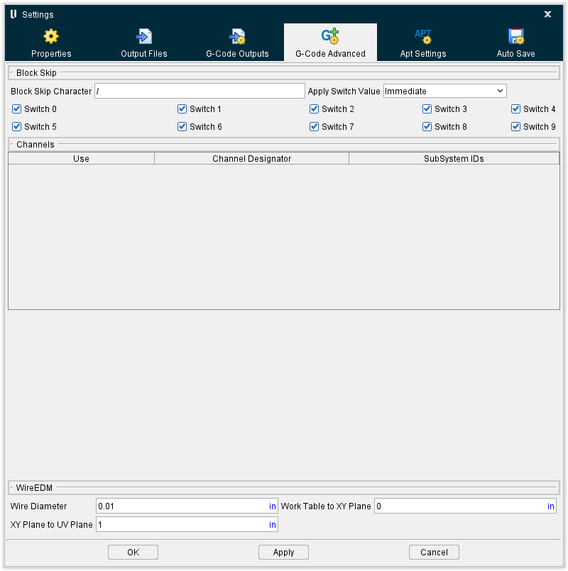
Block Skip
The features in the Block Skip group of the G-Code Advanced tab control which levels of block skipping are recognized, and specify the block skip character.
Block Skip Character — Character which causes the block to be skipped. This character must be the first character in the data block for skipping to occur.
Apply Switch Value — Controls when block skip switch values are referenced by Vericut.
Options:
-
Immediate — Reference switch settings when Vericut is reset, upon loading a new Project file, and any time tool path processing is started.
-
On Reset — Reference switch settings only when Vericut is reset, or upon loading a new Project file.
Switch 1-9 — When active, processing is skipped for blocks beginning with the designated block skip switch. For example, "Switch 2" corresponds to blocks beginning with "/2", "Switch 3" corresponds to blocks with "/3", and so on.
Channels
The features in the Channels group of the G-Code Advanced tab enable you to select which SubSystem is to be used. This setting is only applicable if Sync Method on the Control Settings window, Channels tab is set to something other than None. The features on the Control Settings window, Channels tab are used to set up the sync environment.
The features in this group are intended to be used as a debugging tool enabling you to easily turn off one or more synchronized subsystems rather than running them all at the same time. Vericut still runs through the "Sync" logic but a subsystem that is turned off, behaves like it is in a permanent "Wait" state.
Use — The checkbox in this field enables you to toggle a particular Sync Subsystem on, or off. When toggled "Off", Vericut runs through the "Sync" logic but behaves like it is in a permanent "Wait" state.
Channel Designator — This field shows what is driving each channel. The information displayed here will be different depending on the Sync Method being used. The above picture illustrates a Fanuc control where each channel is driven by a separate NC program.
SubSystem IDs — This field shows the ID of the sync subsystem that the record represents.
WireEDM
The features in the WireEDM group of the G-Code Advanced tab enable you to configure Vericut for Wire EDM simulations.
Wire Diameter — Use to specify the effective cutting diameter of the wire.
Work Table to XY Plane —* Distance from the top of the work table (Machine Z zero) to the XY reference plane, as measured along the machine Z-axis. This value is usually zero, but can be a positive or negative value. The XY reference plane is the Z-axis height at which the tool path file X and Y values are driven.
XY Plane to UV Plane — Distance from the XY reference plane to the UV reference plane, as measured along the machine Z-axis. This value must be a positive value. This setting is only used when the tool path file contains U and V-axis values to control the wire angle. The UV reference plane is the Z-axis height at which the tool path file U and V values are driven.
Settings window, APT Settings tab
The features on the Settings window, APT Settings tab enable you to configure the settings required to support the processing of APT-CLS NC program files.
💡 Tip: You can also access the Settings window, APT Settings tab by selecting Project tab > Settings dropdown menu > APT Settings.
Motion
The features in the Motion group of the APT Settings tab provide important settings for APT-CLS NC program simulation, such as: how circle and rapid motions are simulated, default tool path units, and more.
Default NC Program Units — Default unit measurement system for NC program files that do not contain a "UNITS" record. If the NC program file units differ from the session units, values in the NC program are converted appropriately while being processed.
MULTAX — When selected, interprets six parameter GOTO records as GOTO/x,y,z,i,j,k where i,j,k is tool axis orientation (superseded by MULTAX/OFF). Clearing this checkbox interprets these records as GOTO/x1,y1,z1,x2,y2,z2 - two point locations (superseded by MULTAX/ON).
Max Tool Axis Angle — The maximum angle (in degrees), measured along a multi-axis motion used to display intermediate tool positions. A value of "0" (default) does not display intermediate positions on multi-axis motions. The cut model is unaffected by this feature.
Tool Axis Reset Angle — Minimum angle (in degrees) which is considered a positioning move. Multi-axis motions having angles equal to or greater than the reset angle do not remove material. Instead, the tool display is turned off through the multi-axis motion, then turned on after the multi-axis destination is reached. Cutting resumes at the new tool position.
Closed Circle Tolerance — The Closed Circle Tolerance value is used by Vericut to determine whether a circular motion should go around the whole circle, or just around a small arc of the circle.
A value of zero in this field causes Vericut to check whether a circle is meant to be a complete loop using the same method it has used for many years.
A non-zero value causes Vericut to use a new method for determining whether a circle is meant to be a complete loop. Vericut compares the specified Closed Circle Tolerance value with the distance between a circle's start, and end, points. If the distance is less than the specified tolerance, Vericut assumes that the tool must move round the whole circle. If the distance is greater than the specified tolerance, then Vericut moves the tool around a small arc of the circle.
Process Circles — When selected, processes CIRCLE records to simulate the arc motion. Clear this checkbox to ignore "CIRCLE" records, such as necessary when CIRCLE records are accompanied by their representative chordal GOTO points.
📝 NOTE: Simulating circle motions increases performance dramatically over processing chordal GOTO points.
Reverse Circles — When selected, reverses CIRCLE record motions. Clear this checkbox to simulate circle motions in the direction programmed. (Circle IJK values determine circle direction.)
Detect Chordal GOTOs — When this option and Process Circles are selected, the chordal GOTO points which follow CIRCLE records motions are processed to simulate an arc, or circle motion. Clear this checkbox to process the GOTOs as linear tool positions.
Reset Tool Change — When selected, resets the tool display following a tool change. This action turns off the tool display until after the tool is changed and the following motion is processed. The new tool appears at the end of the motion following the tool change. This option is recommended when simulating tool paths for NC machines that automatically retract the tool during a tool change. Clear this checkbox to have Vericut change the tool at its current location when a tool change command is encountered.
Process NX or CATIA Matrix — When selected, processes these tool path matrix records to transform the tool path to its base coordinate system: CATIA0 or MSYS. Clear this checkbox to ignore tool path matrix records. This feature is useful to automatically orient tool paths to models imported from the same CAD/CAM system.
Ignore unrecognized Major words — When toggled on, Vericut ignores unrecognized APT major words and no warning messages are output to the Vericut main window message area, or in the Log file.
Default CLEARP — Distance to retract along the tool axis when a RETRCT record is encountered prior to establishing the retract plane. The default CLEARP condition is "off" until a CLEARP record defining a clearance plane is encountered.
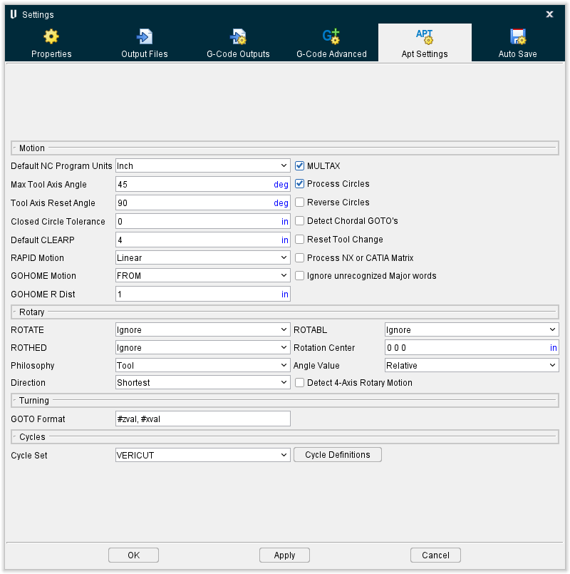
RAPID Motion — Controls how to simulate rapid positioning motions. Options:
-
Linear — Move in a straight line.
-
Square — Move with "squared off" motion, where Z motions are processed independently from X and Y.
GOHOME Motion — Controls how the tool is returned to the home position when a GOHOME record is processed. Options:
-
FROM — Move in a straight line to the home position.
-
Retract — Move with squared off motion, where the tool is first retracted the distance specified by the GOHOME R Dist value, then moved to the home position.
GOHOME R Dist — When simulating GOHOME record motions via the "Retract" option (see above), this value specifies the distance to retract before going to the home position.
Rotary
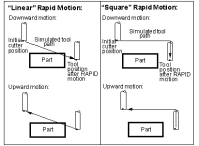
The features in the Rotary group of the APT Settings tab enable you to control the rotary motions simulated for APT-CLS NC programs. Note that while machines often rotate the workpiece, in a Vericut Workpiece view the workpiece is fixed and the tool is seen rotating about the workpiece. Both rotary cut paths are identical.
"ROTATE/BAXIS,ATANGL,90" as seen on a machine with a "B" rotary table and simulated by Vericut in a Workpiece view:
ROTATE, ROTABL, ROTHED — These features control when and how to simulate motion caused by the corresponding ROTATE, ROTABL, or ROTHED records, respectively. "BAXIS" is the default rotation axis when not specified. The rotary pivot point is defined by the Rotation Center. When absolute or incremental rotation is not specified, the Angle Value determines how to apply the rotary value. Options:
-
Ignore — Ignores the rotary command. (Default)
-
Rotate — Rotates while cutting. Tool path motions that follow are expected to have the rotation applied.
-
Rotate/Apply — Similar to Rotate, except also applies the rotated coordinate system to subsequent tool path motions. Tool path motions that follow are NOT expected to have the rotation applied.
-
Position — Rotates without cutting, also known as "positioning". The tool disappears from its initial position, and then appears at the rotated position. Tool path motions that follow are expected to have the rotation applied.
-
Position/Apply — Similar to Position, except also applies the rotated coordinate system to subsequent tool path motions. Tool path motions that follow are NOT expected to have the rotation applied.
Rotation Center — Center of rotation for rotary motions simulated via the ROTATE, ROTABL, or ROTHED features (see above).
Philosophy — Describes what is being commanded to rotate for rotary motions simulated via the ROTATE, ROTABL, or ROTHED features (see above): Table (default), or Tool. Changing the rotation philosophy has the effect of reversing rotation direction. Note that ROTHED angle values are always assumed to use a rotating Table philosophy.
Angle Value — Controls how angle values are applied for rotary motions simulated via the ROTATE, ROTABL, or ROTHED features (see above) when the commands do not specify "ATANGL" or "INCR". Options:
-
Relative — Incremental angle values.
-
Absolute — Absolute angle locations. (Default)
📝 NOTE: ROTHED angle values are always assumed to be Absolute.
Direction — Direction of rotation for simulating for rotary motions simulated via the ROTATE, ROTABL, or ROTHED features (see above). Options:
-
Shortest — Direction which travels the shortest distance. (Default)
-
CW — Always use clockwise motion.
-
CCW — Always use counterclockwise motion.
-
Linear — Refers to angles on a linear axis "wrapped" around the rotary component. Rotary values specify absolute locations along the linear-rotary axis, while the sign (+ / -) controls which end of the linear axis is used.
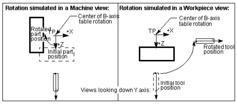
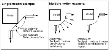
Detect 4-Axis Rotary Motion — When selected, simulates an arc cut for multi-axis motions that fit within an arc path. Clear this checkbox to simulate each multi-axis motion independently- recommended when simulating 5-axis contouring-type motions. The Interpolation Tolerance value is used to determine which motions are simulated in the 4-axis cut.
Turning
The features in the Turning group enable you to control lathe turning motions simulated for APT-CLS NC program files.
GOTO Format — Use to specify how turning GOTO record values are to be displayed in a Workpiece view. In this view, Vericut simulates turning motion in the ZX plane, where Z is the spindle-axis, and X is the cross-slide-axis. This feature acts like a post-processor for turning tool position data.
Example 1 — Assume you have a turning tool path programmed in GOTO/x,y format. By default, GOTO Format "#zval, #xval" displays the first GOTO value as Z-axis motion, and the second value as X-axis motion.
Example 2 — Assume you have a turning tool path that was reversed post-processed from G-Code data such that GOTO records are in GOTO/x,0,z format (center value is "zero"). For Vericut to process this correctly, set GOTO Format= #xval, #yval, #zval.
Cycles
The features in the Cycles group of the APT Settings tab enable you to change how Vericut simulates the APT, or CLS, CYCLE records when simulating NC program canned cycles, also known as "fixed tool axis cycles". The Drill Cycle feature controls when and how these records are simulated.
Cycle Set — Controls which cycle definition set(s) are considered by Vericut when processing APT tool paths. If you add a new cycle set, for a different flavor of APT or a different post-processor, you can give it any name you wish and it will appear in this list. "ALL" considers all cycle sets defined for use.
Cycle Definitions — Opens the Cycles window enabling you to maintain cycle and modals definitions used to interpret "CYCLE" records. This feature is especially useful if simulated cycle motions are not displayed as expected. When Vericut cannot find definitions to interpret a CYCLE record, an error similar to "Invalid CYCLE record" error is issued. In these cases, cycle definitions must be modified to interpret the cycle data.
Configuring for APT-CLS Cycle Simulation
By default, Vericut simulates the motions of popular canned cycles, also known as "fixed tool axis cycles", as described by the APT or CLS CYCLE record. If needed, Vericut also enables you to add more, and change, how existing cycles are interpreted. To do so, it must have access to cycle definitions, which are retained in the Project file. The cycle definitions for one flavor of APT are referred to as a cycle definition set, or more simply, a cycle set.
You can adjust the definitions of the distributed cycles, add definitions to the sets, or provide different sets of your own using features located on the Project tab > Settings dropdown menu > APT Settings > APT Settings: Cycles tab.
The three parts of a cycle definition
So what does a cycle definition look like? Let's examine an example from the default Project files:
CYCLE/BORE,#fedto,#fedupm,MMPM,#rapto

MODALS:retract_mode=fedrat

USEWITH:Vericut,CADRA,CV
A cycle definition can have three parts, the CYCLE statement, optional MODALS and USEWITH lines. This example is a member of three sets, for Vericut, CADRA and CV flavors of APT, but more typically there would be just one flavor in the USEWITH line.
This document will explore each of the three parts of a cycle definition in detail.
Cycle template
A cycle template appears similar to the CYCLE record to simulate. Numeric values in the statement that are relevant to the anticipated motion are replaced by mnemonics in the template. The major and minor words can simply be reproduced. For example, the following CYCLE record:
CYCLE/DRILL,40,200,MMPM,5
can be represented by the following cycle template:
CYCLE/DRILL,#fedto,#fedupm,MMPM,#rapto
Note that mnemonics all start with a "#" character to denote a numeric value. There are a limited number of valid mnemonics, with predefined and rigid interpretations. A description of each mnemonic is provided under the heading "Mnemonics for cycle templates" later in this section.
A cycle statement may contain numeric values which are not covered by any of the mnemonics, and which do not affect simulated cycle motion, for example- dwell time. Such values can be represented in the template by a "#" character without a mnemonic. Think of them as placeholders for the values. For example:
CYCLE/REAM,60,5,1,1,5,200,10,ON
can be represented by:
CYCLE/REAM,#fedto,#rapto,#,#,#rtrcto,#fedupm,#,A
The placeholders enable Vericut to extract numeric values that affect the motion, in this case represented by #fedto, #rapto, #rtrcto and #fedupm, and ignore values that are not significant for simulating cycle motions.
In the above example, note that the minor word "ON" is not replicated in the template of this example. A similar ream CYCLE record could have the minor word "OFF". Rather than having two templates that only differ by the last minor word, we can use a placeholder for a word and cover the variations with a single template. "#" is a placeholder for a numeric value. You can use "A" or any word as a placeholder for a minor word that is not significant for simulating cycle motions.
But, there are two situations in which minor words must be replicated in the template.
-
If a minor word precedes the first numeric value, it must appear in the template explicitly. So in the prior example, "REAM" is replicated.
-
If a minor word is paired with a mnemonic, it must appear in the template.
For example:
CYCLE/BORE,FEDTO,60,MMPM,200,RAPTO,5
should be represented by:
CYCLE/BORE,FEDTO,#fedto,MMPM,#fedupm,RAPTO,#rapto
because each minor word after "BORE" is paired with a corresponding mnemonic. This enables Vericut to process cycle statements with the same minor words in a different order, without requiring extra templates. Thus:
CYCLE/BORE,FEDTO,60,RAPTO,5,MMPM,200
would be covered by the same template as the prior example. Usually word/value pairs are in that order, but a feed rate and its units can be reversed. To phrase the rules for minor words another way, it is safest to replicate all minor words in the cycle template unless there are alternatives to a word. If there are alternatives and they precede all values, or are paired with a mnemonic, then it is necessary to enumerate the alternatives in several templates.
Minor word synonyms
Minor words for the units of feed rate are interchangeable, or "synonyms". Thus if you process APT files with imperial units and other APT files with metric units, you do not need multiple templates such as:
CYCLE/BORE,FEDTO,#fedto,IPM,#fedupm,RAPTO,#rapto
CYCLE/BORE,FEDTO,#fedto,MMPM,#fedupm,RAPTO,#rapto
Either of these templates will suffice for either unit.
Within cycle templates the following minor words are synonyms:
-
IPM — inches per minute
-
MMPM — millimeters per minute
-
FPM — feet per minute
-
IPR — inches per revolution
-
MMPR — millimeters per revolution
-
FPR — feet per revolution
-
TPI — threads per inch
-
TPMM — threads per millimeter
Adding a minus sign to a mnemonic
Normally mnemonics consist of the character "#" and a word. But there can be a "-" sign between the "#" and the word if the corresponding value in a cycle statement is to be negated. This will handle the case that some post-processors expect a positive fedto ("feed to") value, while others expect a negative value for this action. By default, Vericut assumes a positive fedto value will move toward or into the workpiece. While the "-" sign can be applied to any mnemonic, it is only likely to be used with fedto or fedlist.
Mnemonics for cycle templates
Following is an explanation of each mnemonic, in alphabetic order:
cskdia — Countersink diameter. Typically this mnemonic appears with another, tlangl and perhaps a third, holdia. If no tool angle is provided, a value of 118 degrees is used. If a hole diameter is provided then an initial rapid motion can be adjusted to place the tool partially within the hole prior to cutting. It doesn't make much sense to have a fedto distance with a countersink diameter. If one is provided, it will be ignored.
fedto — Feed depth from the cycle's datum (typically a GOTO point). Use "#fedto" if a positive value implies motion into the material. Use "#-fedto" if a negative value implies motion into the material.
fedlist — A list of increasing feed depths. A single mnemonic of this type represents any number of values in the cycle statement. For example if you have a statement like:
CYCLE/DEEP,DEPTH,10,20,25,MMPM,100
the template could be:
CYCLE/DEEP,DEPTH,#fedlist,MMPM,#fedupm
and it would handle statements with any number of depths between the minor words "DEPTH" and "MMPM" (or one of its synonyms). Use "#fedlist" if a positive value implies motion into the material. Use "#-fedlist" if a negative value implies motion into the material.
fedupm — Feed rate in units determined by the associated minor word in the cycle statement (if any).
holdia — Hole diameter. Only meaningful if a cskdia is also present.
rapto — Rapid clearance distance above the cycle's datum. The tool moves at Rapid to this clearance location prior to executing the cycle motion. If a retract distance (rtrcto) is not provided, this value will also serve as the retract clearance distance.
rtrcto — Retract distance above the cycle's datum. If the cycle involves multiple retract motions, such as a pecking operation, all the retract motions may or may not be to this height, but the last one always will be.
step — An incremental depth by which each successive feed in a pecking operation will increase. It is possible to have more than one step within a cycle statement if the increments are not equal. For example:
CYCLE/DEEP,DEPTH,70,STEP,30,STEP,15,MMPM,100
would be handled as expected by:
CYCLE/DEEP,DEPTH,#fedto,STEP,#step,MMPM,#fedupm
In this example the first feed would be to 30mm, then 45mm and 60mm, and finally to 70mm. It is not necessary to place "STEP" or "#step" in the template more than once, and any number of "STEP, value" pairs could appear in the cycle statement.
steplist — A list of incremental depths for each successive feed. This differs from the prior example in that the values are not separated by repetitive minor words. For example:
CYCLE/DEEP,DEPTH,70,STEP,20,15,10,MMPM,100
would be represented by:
CYCLE/DEEP,DEPTH,#fedto,STEP,#steplist,MMPM,#fedupm
In this case successive feeds would be to 20mm, 35mm, 45mm, 55mm, 65mm and 70mm.
steprap — Distance above the prior depth that the tool will move to before the next deeper feed. If the cycle retracts completely between successive feeds, the tool moves at Rapid and in the downward direction after each Retract. If the cycle only partially retracts between feeds, then this motion is in the upward direction and may or may not be rapid.
tlangl — The included angle of the tool tip for countersink operations. Only meaningful if a cskdia is also present.
Modal specification
Each cycle definition can specify a number of modal values to control details of the cycle motion. All modals have default values, and it is not necessary to define the settings of those that take these default conditions. If all of a definition's modals take the defaults, the "MODAL" line can be omitted.
Following is an explanation of each modal and its default value, in alphabetic order:
auto_mode — (default OFF) Controls whether the automatic retract plane should be used. When set to "ON", any value corresponding to the rtrcto mnemonic will be ignored and the final retract of the cycle will be to the automatic retract plane. Cycle statements may differ by only "AUTO" as a minor word. Rather than requiring two similar cycle templates, Vericut will turn this modal "ON" if a cycle statement contains "AUTO". It is thus only necessary to include this modal in the "MODAL" line of a cycle definition, if some other feature of the cycle statement is the trigger.
cycle_op — (default ON) Controls whether cycle statements that match a definition are to be expanded at all. An alternative to "cycle_op=OFF" would be to toss out the entire definition, but then the Vericut log would report unrecognized cycles. Use this modal if you wish emulate some cycles but not others.
deep_retract — (default ON) Controls whether the tool should retract completely between successive feeds. When turned "ON" the tool will retract to the height specified by the rtrcto mnemonic (or rapto if there is no rtrcto) between feeds. If "deep_retract=OFF", then between feeds the tool will retract incrementally by the distance corresponding to the steprap mnemonic, or simply dwell if there is no such value. This modal has no meaning if there is only one feed depth.
rapto — (default 0) Can be used to provide a "rapid to" distance when none is present in the toolpath's CYCLE statement.
retract_mode — (default RAPID) Controls the feed rate used for all retract motions in the cycle. With the default setting, all retracts will be rapid. Other options are "retract_mode=FEDRAT" and "retract_mode=NONE". "FEDRAT" would be used when the retract motion should be at the same speed as the feed, such as in a ream or tap cycle. "NONE" would be used to suppress retract motion completely, as in a milling cycle.
rtrcto — (default 0) Can be used to provide a retract distance when none is present in the toolpath's CYCLE statement.
thru_mode — (default OFF) Controls the feed rate of successive feeds. When this modal is "ON", the first feed is at the feed rate, the second is rapid, the third is at the feed rate, etc. This can be used when the tool is passing through several webs, and it can be moved quickly through the air between the webs. This modal has no meaning if there is only one feed depth.
Applicability (USEWITH)
The USEWITH line of a cycle definition can list the names of one or more flavors of APT. All of the unique flavors present in a user file are presented in a choice box on the Project tab > Settings > APT Settings: Cycles tab. When you select one of the flavors in the choice box, Vericut will only consider corresponding cycle definitions when processing your APT NC programs.
If you add a new cycle set, for a different flavor of APT or a different post-processor, you can give it any name you wish, provided the name does not contain spaces or other APT delimiter. So your cycle definitions may each end with:
USEWITH:MYPOST
An alternative would be to delete all the cycle definitions in the project file and insert yours, omitting the USEWITH line for each. Then the choice box would just offer "All", however, only your definitions would be present.
Cycle definition sets
In alphabetic order, the sets of cycle definitions provided in the default project files simulate the following flavors of APT-CLS canned cycles:
All
ACL
CADRA
CATIA
CONVERTED — generated by Vericut via reverse post-processing from G-Code
CV — ComputerVision
GEN4AX — a post used with NCL
NCL — combines GEN4AX and POSTWORKS sets
POSTWORKS — a post used with NCL
PTC — Pro/Manufacturing
NX — NX CLS
Vericut
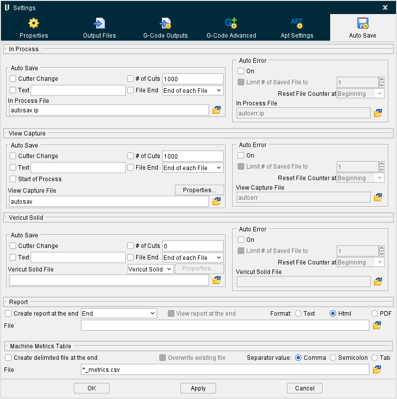
Settings window, Auto Save tab
The features on the Settings window, Auto Save tab enable you to configure Vericut to automatically save In Process files, View Capture image files (such as PostSript, EPSF, TIFF, JPEG or PNG files), or Vericut Solid (.vct) files. Saving is based on user specified events or when Vericut detects errors during NC program processing. Auto-saving is especially useful to save data during batch processing.
By default, unique file names are maintained based on the following naming convention:
"Basefilename + seq# + setup# + file# + line# + tool#"
For example: test1S1F1L350T3.vct
test = basefilename

1 = sequence #1 (First file automatically saved. The next file automatically saved will be seq. 2, and so on)

S1 = setup #1

F1 = File (NC program) #1 for this setup.

L350 = Line #350 caused file to be saved.

T3 = Tool #3 was in use when file was automatically saved.
When multiple stock components are defined, the naming convention is altered slightly to include an "M" identifier for .vct files saved after the first one. For example, when two stock components were defined, the following models were automatically saved at end of file:
test1S1F1L350T3.vct <= NO "M" identifier for the first model automatically saved for the first cut stock.

test2S1M1F1L350T3.vct <= "M1" added for the second model automatically saved for the second cut stock
You also have the option of turning off one, or more of the individual fields, described above, for the automatically generated output filenames.
If you want to turn off specific fields, you can do so by specifying which fields you want included in the name, by using the following format when you specify the “base file name” for the file to be auto-saved:
name[IMSFLT].ext

I: Turns on the unique Index value

M: Turns on the Model number (This option is only applicable for auto-saving Vericut Solid files when there are multiple stock components)

S: Turns on the Setup number

F: Turns on the File number

L: Turns on the Line number

T: Turns on the Tool number
📝 NOTE: Using name[IMSFLT].ext (all options) is identical to the default naming convention with multiple stock components.
The following rules apply when customizing the output file name:
-
The field descriptions described for the output file name still apply.
-
The letters only specify which fields to include in the output file name.
- The order of the fields is fixed and must not be changed.
- The letters can be lower or upper case.
- The square brackets must come after the name and before the file extension.
- The brackets and file extension are optional.
The above feature applies to:
-
Auto Save In Process File
-
Auto Error In Process File
- Auto Save View Capture File
- Auto Error View Capture File
- Auto Save Vericut Solid File
- Auto Error Vericut Solid File
- The SaveVcSolid macro
EXAMPLES:
| File Name Input | File Name Output |
|---|---|
| name.vct | name1S1F1L15T43.vct |
| name[] | name.vct |
| name[T] | nameT43.vct |
| name[IT].vct | name1T43.vct |
In Process
The features in the In Process group of the Auto Save tab enable you to control the automatic saving of In Process files, or "IP files".
Auto Save options — These options control when Vericut automatically saves IP files. Click on the box to the left of the event to toggle On/Off. Each selected event causes a file to be saved when that event occurs. Options:
-
Cutter Change — Save an IP file when the cutter has been changed.
-
Text — Save an IP file when a specified text string is encountered in the NC program. Enter the text string in the Text text field.
-
# of Cuts — Save an IP file after a specified number of cuts. Enter the number of cuts in the # of Cuts text field.
-
File End — Save file at the end of NC program processing. Choose either End of each File (end of each NC program file), End of each Setup, or End (end of the program) from the pull-down list.
-
In Process File — Use to specify the base name for IP files saved. Enter the \path\filename in the In Process File text field or click on the
 (Browse) icon and use the Save File file selection window to specify the \path\filename. The naming convention used for saved IP files is as described above under Auto Save tab.
Auto Error options
Use these options to specify whether or not Vericut automatically saves Vericut Solid files when an error is detected. Options:
-
On — When toggled "on" (checked), Vericut automatically saves an IP file for every error that is detected.
-
Limit # of Saved File to — When active (checked), this feature enables you to specify the maximum number of IP files that you want automatically saved due to errors during a specified event. The Limit # of Saved File to feature is only available when the Auto Error On feature is toggled "on" (checked). When the Limit # of Saved File to feature is toggled "on" (checked), the associated fields become available. Enter the maximum number of IP files that you want created in the text field or use the "up"/"down" arrows to increase or decrease the number shown in the text field to the desired number. Select the event that the number specified above is to apply to from the pull-down list. Choose from the following events:
-
Beginning — Vericut will output the specified number of IP files for the entire simulation.
-
Start of Setup — Vericut will output the specified number of IP files for each setup.
-
Start of File — Vericut will output the specified number of IP files for each NC program file.
-
Tool Change — Vericut will output the specified number of IP files for each tool change.
-
In Process File — Use to specify the base name for IP files saved. Enter the \path\filename in the In Process File text field or click on the
(Browse) icon and use the Save File file selection window to specify the \path\filename. The naming convention used for saved IP files is as described above under Auto Save tab.
View Capture
The features in the View Capture group enable you to control the automatic saving of View Capture image files (PostSript, EPSF, TIFF, JPEG or PNG).
Print Command — When toggled "Off", sends graphical data to the specified View Capture image file. When toggled "On", executes the print command that sends raw graphical image data to the printer.
By default, the "prshade" command executes the "prshade" command file containing operating system commands typically used to print images on your computer. If printing fails, correct the entry in the Print Command field, or use an ASCII text editor (NOT a word processor) to edit the "prshade" command file to have the proper print command for your computer/printer.
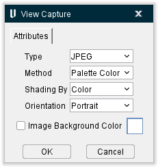
Properties — Opens the View Capture window, enabling you to specify capture VERICUT images and format them for printing or importing into desktop publishing applications.
-
Type — Type of format in which to capture VERICUT images. Printer-ready and electronic formats are available. Options:
-
PostScript — Postscript format.
-
EPSF — Encapsulated PostScript File.
-
TIFF — Tag Image Format File.
-
JPEG — JPEG compressed format. (JPEG image support based in part on the work of the Independent JPEG Group.)
-
PNG — PNG (Portable Network Graphics) format.
-
Method — Method of coloring the captured image. Options:
-
Standard — black and white only
-
Grayscale — black and white with shading
-
RGB Color — Red-Green-Blue values for each pixel
-
Palette Color — Red-Green-Blue color tables
-
CMYK Color — Cyan-Magenta-Yellow-Black color tables
-
Shading By — Method that is to be used for shading black and white images.
-
Intensity — Shade by light intensity only, for example: the brightest yellow color is the same shade of gray as the brightest blue color.
-
Color — Shade by color differences and light intensity.
-
Orientation — Controls image orientation on the printed page: Landscape or Portrait.
-
Image Background Color — Sets the color that will be used in the background of the captured view.
-
OK — Saves the View Capture window settings and closes it without outputting an image file.
-
Cancel — Closes the View Capture window without saving setting changes or outputting an image file.
Auto Save options
These options control when Vericut automatically saves View Capture image files. Click on the box to the left of the event to toggle On/Off. Each selected event causes a file to be saved when that event occurs. Options:
Cutter Change — Save a View Capture image file when the cutter has been changed. This feature can also be used to capture images of electrodes used for Die Sinking Simulation when they are changed during the burn process.
Text — Save a View Capture image file when a specified text string is encountered in the NC program. Enter the text string in the Text text field.
# of Cuts — Save a View Capture Image file after a specified number of cuts. Enter the number of cuts in the # of Cuts text field.
File End — Save a View Capture image file at the end of NC program processing. Choose either End of each File (end of each NC program file), End of each Setup, or End (end of the program) from the pull-down list.
View Capture File — Use to specify the base name for View Capture image files saved as a result of Auto Save options described above, when the Print Command checkbox is toggled "Off". Enter the \path\filename in the View Capture File text field or click on the (Browse) icon and use the Save File file selection window to specify the \path\filename. The naming convention used for saved View Capture image files is as described above under Auto Save tab.
Auto Error options
These options control when Vericut automatically saves View Capture image files due to errors. Options:
On — When toggled "on" (checked), Vericut automatically saves a View Capture image file for every error that is detected.
Limit # of Saved File to — When active (checked), this feature enables you to specify the maximum number of View Capture image files that you want automatically saved due to errors during a specified event.
The Limit # of Saved File to feature is only available when the Auto Error On feature is toggled "on" (checked). When the Limit # of Saved File to feature is toggled "on" (checked), the associated fields become available.
Enter the maximum number of View Capture image files that you want created in the text field or use the "up"/"down" arrows to increase or decrease the number shown in the text field to the desired number.
Select the event that the number specified above is to apply to from the pull-down list. Choose from the following events:
-
Beginning — Vericut will output the specified number of View Capture image files for the entire simulation.
-
Start of Setup — Vericut will output the specified number of View Capture image files for each setup.
-
Start of File — Vericut will output the specified number of View Capture image files for each NC program file.
-
Tool Change — Vericut will output the specified number of View Capture image files for each tool change.
-
View Capture File — Use to specify the base name for View Capture image files automatically saved as a result of errors detected when AutoError On is toggled "On", and the Print Command checkbox is toggled "Off". Enter the \path\filename in the View Capture File text field or click on the
(Browse) icon and use the Save File file selection window to specify the \path\filename. The naming convention used for saved View Capture image files is as described above under Auto Save tab.
Vericut Solid
The features in the Vericut Solid group of the Auto Save tab enable you to control the automatic saving of Vericut Solid (vct.) files.
Auto Save options
Use these options to specify the events when Vericut should automatically save Vericut Solid files. Click on the box to the left of the event to toggle On/Off. Each selected event causes a file to be saved when that event occurs. Options:
-
Cutter Change — Save a Vericut Solid file when the cutter has been changed.
-
Text — Save a Vericut Solid file when a specified text string is encountered in the NC program. Enter the text string in the Text text field.
-
# of Cuts — Save a Vericut Solid file after a specified number of cuts. Enter the number of cuts in the # of Cuts text field.
-
File End — Save a Vericut Solid file at the end of tool path processing. Choose either End of each File (end of each NC program file), End of each Setup, or End (end of the program) from the pull-down list.
-
Vericut Solid File — Use to specify the base name for Vericut Solid files saved due to Auto Save options. Enter the \path\filename in the Vericut Solid File text field or click on the
(Browse) icon and use the Save File file selection window to specify the file. The naming convention used for saved Vericut Solid files is as described above under Auto Save tab.
Auto Error options
Use these options to specify whether or not Vericut automatically saves Vericut Solid files when an error is detected. Options:
-
On — When toggled "on" (checked), Vericut automatically saves a Vericut Solid file for every error that is detected.
-
Limit # of Saved File to — When active (checked), this feature enables you to specify the maximum number of Vericut Solid files that you want automatically saved due to errors during a specified event. The Limit # of Saved File to feature is only available when the Auto Error On feature is toggled "on" (checked). When the Limit # of Saved File to feature is toggled "on" (checked), the associated fields become available. Enter the maximum number of Vericut Solid files that you want created in the text field or use the "up"/"down" arrows to increase or decrease the number shown in the text field to the desired number. Select the event that the number specified above is to apply to from the pull-down list. Choose from the following events:
-
Beginning — Vericut will output the specified number of Vericut Solid files for the entire simulation.
-
Start of Setup — Vericut will output the specified number of Vericut Solid files for each setup.
-
Start of File — Vericut will output the specified number of Vericut Solid files for each NC program file.
-
Tool Change — Vericut will output the specified number of Vericut Solid files for each tool change.
Vericut Solid File — Use to specify the base name for Vericut Solid files saved when AutoError is active. Enter the \path\filename in the Vericut Solid File text field or click on the (Browse) icon and use the Save File file selection window to specify the file. The naming convention used for saved Vericut Solid files is as described above under Auto Save tab.
Report
The features in the Report group of the Auto Save tab enable you to automatically save a Vericut report at the end of processing, automatically view the report at the end of the simulation, and specify the format for the report.
Create report at the end — When toggled on (checked), Vericut will automatically create a Vericut report at the end of processing.
View report at the end — When toggled on (checked), Vericut will automatically display the Vericut report created at the end of processing so that you can view it.
Format — Use this feature to specify the format that you want Vericut to use for the report. Choose one of the following formats.
Text — Creates and displays the Vericut Report in Text format.
HTML — Creates and displays the Vericut Report window in HTML format.
PDF — Creates and displays the Vericut Report in PDF format.
File — Enter the /path/filename where you want the Vericut report created, or use the (Browse) icon to display the Save Vericut Report file selection window and use it to specify the /path/filename.
For more information on creating and using custom report templates, see Report Template window section of Vericut Help.
Machine Metric Table
The features in the Machine Metric Table group of the Auto Save tab enable you to automatically save a delimited data file at the end of processing, overwrite existing file, and specify the separator value.
Create delimited file at the end — When toggled on (checked), Vericut will automatically create a delimited file at the end of processing.
Overwrite existing file — When toggled on (checked), Vericut will automatically overwrite existing file define in File.
Separator value — Choice of Comma or Semicolon or tab as separator value in the delimited file.
File — Enter the \path\filename where you want the delimited file created, or use the (Browse) icon to display the delimited file selection window and use it to specify the \path\filename.
For more information on creating and using custom report templates, see Report Template window and especially Machine Metric section sections of Vericut Help.