Offsets
Location:
Project tab >  (Offsets pulldown menu)
The Offsets command button allows you to add, modify, and delete G-Code Offsets . Selecting this option displays a pulldown menu that allows you to open any of three separate panels: Offsets: G-Code panel, Offsets: Location panel, or Offsets: Tool panel. These panel functions are also explained in the Configure Work Offsets section of Vericut Help
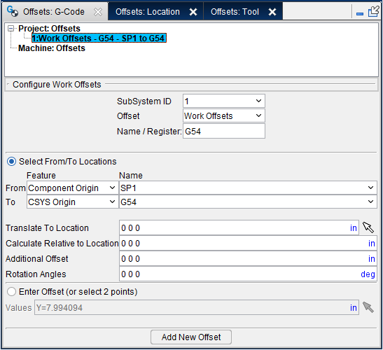
Offsets: G-Code panel
SubSystem ID — Use to specify ID of the machine subsystem for which the table is being defined.
Offset — Use to identify the type of offset table to be added, or modified, if it already exists. Choose one of the following offset table types from the pull-down list.
Base Work Offset — The Base Work Offset table specifies the location from which work offsets are based. Use this table when the NC program file references a base work coordinate system (e.g. G52) from which all other work offsets are based. (Ref. "Work Offsets table" section of Vericut Help).
Work Offsets — The Work Offsets table stores work coordinate system offset, or "fixture offset" values. Use this table when simulating programming with work offsets (e.g. G53-59). Enter values to represent the work offset values entered at the NC control. Work coordinate system offset values that are automatically loaded using data in the NC program file (e.g. G10L2Pn) do not require entry.
Shift Offsets — The Shift Offsets table stores work coordinate system offsets similar to Work Offsets.
Program Zero — The Program Zero table is used to specify the programmed zero location of a G-Code NC program file taking Tool Length Compensation into consideration. This table is required when the machine operator establishes a zero location other than machine zero. This activity is also known as establishing a "floating zero" location.
Name/Register — The Name or Register number that will be used by Vericut to access corresponding table data. The Name or Register number may correspond to an offset register number, or an integer value, as required by a particular table.
Component — The Component that will be used by Vericut to create the Work Offset. Options for this pulldown menu include Stock, Fixture, Attach, and Spindle.
CSYS — The CSYS that will be used by Vericut to create the Work Offset. Options for this pulldown menu include any configured CSYS or the Stock.
Select — The Select feature enables you to create a Work Offset by selecting regions of the model in the display window. Click on the arrow icon ![]() at which point it will become highlighted
at which point it will become highlighted  . Once the arrow is highlighted, you can select the area of the model to create a Work Offset from. Options for what can be selected include: Vertex, Component Origin, CSYS Origin, and 3 planes.
Enter Offset — The Enter Offset field allows you to enter the value of your desired Work Offset.
Add — The Add feature is used to add the Work Offset to the table once all other values have been set.
Offsets: Location panel
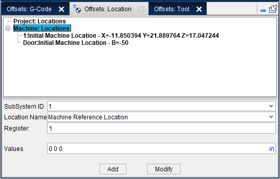
SubSystem ID — Use to specify ID of the machine subsystem for which the table is being defined. Select from the pull-down list of subsystems defined for the current machine.
Location Name — The following Machine Locations table types can be added, or modified, with the features on the Machine Settings window: Locations tab. When adding a new table, select the table type from the pull-down list. If you are modifying an existing table, the table type will automatically be selected.
-
Initial Machine Location — This table specifies where machine axes are initially located. The machine is moved to this location when the machine is first loaded, when Vericut is reset, or the NC program is rewound.
-
Machine Reference Location — This table specifies the reference location of machine axes. The reference location is where the machine axes move to when a "return to reference location" command is processed (e.g. G28), such as typically used with the "Tool Length Compensation" programming method.
-
Machine Reference Retraction — This table specifies which axes to retract, and in what order. This table is used with the Machine Reference Location feature which specifies the location to retract to.
In this table, each axis can have a value. (e.g. 0, 1, 2, 3) 0 means to not move the axis. Any axis not specified defaults to zero. The values 1, 2, and 3 corresponds to move first, second, or third etc.
For example:
X3 Y2 Z1 A3 C3 means retract Z first, then Y, and then X, A, and C. -
Tool Change Location — This table specifies the location of machine axes for changing the tool. This table is used when machine axes are specified to retract during a tool change via the Tool Change Retract Method feature (ref. Control Settings window: Tooling tab), or the Tool Change Retraction table described below.
-
Tool Change Retraction — This table specifies which machine axes retract, and in what order for tool changes.. This table is used only with the Use Retraction Table option for the Tool Change Retract Method feature (ref. Control Settings window: Tooling tab). The retract location of each of the machine’s axes is specified via the Tool Change Location table described above.
-
Turret Rotations — This table stores the turret rotation angles of multiple Tool components connected to a Turret component on a lathe machine. This table is intended for use when one or more Tool components are not defined with tool origin Z-axis values "0 0 1". If the table is not defined and one of these Tool components becomes active, the turret will automatically index to its zero position. To correct this condition, the Turret Rotations table is used to specify the rotation angle for indexing the tool into its cutting position. The table is not required to index Tool components defined with tool origin Z-axis values "0 0 1", since the tool origin X-axis orientation (when defined properly) causes proper turret indexing.
- Head Position — The Head Position table defines default Head rotation and Spindle orientation for specific Position ID. The default positions can then be overridden by the Position table within the Tool Change list.
📝 NOTES:
-
Machine Location tables created here are stored in the machine file (.mch).
-
You can also create Machine Location tables using the features on the Settings window: G-Code Advanced tab. Machine Location tables created there are stored in the project file (.vcproject, .vcsproject, .vdafproject) and will override those stored in the Machine file.
Register — The Register number that will be used by Vericut to access corresponding table data. The Register number may correspond to an offset register number, or an integer value, as required by a particular table.
Values — The Values field allows you to enter the value of your desired Work Offset.
Add — The Add feature is used to add the Work Offset to the table once all other values have been set.
Modify — The Modify feature is used to change the Work Offset in the table after it has already been created.
Adding, Modifying, or Deleting Machine Location Tables
To add a new Machine Locations table:
- In the Configure group of the window, select the desired table type from the Location Name pull-down list.
- Select the SubSystem ID from the pull-down list for the table data that is being defined.
- If you are creating a Machine Reference Location table, enter the Register value.
- If you are creating a Turret Rotations table, enter the Tool Index value.
- Click on the Add button to add the table to the Tables List. Notice that the selected table and a default table record have been added to the Tables List.
-
If you are creating a Turret Rotations table, enter the values representing the A, B, and C axis orientations in the Angles text field.
For all other Machine Location tables enter the values representing the location values for the table you are creating in the Values (XYZABCUVWABC): text field. Multiple value entries require spaces between the values. -
Select Apply to update the table record and leave the window open. Select OK to update the table record and close the window.
Add an additional table record:
- Select the SubSystem ID from the pull-down list for the table record that you are adding.
- If you are creating a Machine Reference Location table, enter the Register value for the table record that you are adding.
- If you are creating a Turret Rotations table, enter the Tool Index value for the table record that you are adding.
- Click on the Add button to add a default table record to the Tables List.
-
If you are creating a Turret Rotations table, enter the values representing the A, B, and C axis orientations in the Angles text field.
For all other Location tables enter the values representing the location values for the table you are creating in the Values (XYZABCUVWABC): text field. Multiple value entries require spaces between the values. -
Select Apply to update the table record and leave the window open. Select OK to update the table record and close the window.
To modify an existing table record:
- In the Settings window: G-Code Advanced tab (Project tab > Settings), click on the table record, in the Tables List, that you want to modify.
-
If you are modifying a Turret Rotations table record, enter the values representing the A, B, and C axis orientations in the Angles text field.
For all other Location tables enter the values representing the location values for the table record that you are modifying in the Values (XYZABCUVWABC): text field. Multiple value entries require spaces between the values. -
Select Apply to update the table record and leave the window open. Select OK to update the table record and close the window.
To delete a table record from the Table list:
Right click on the table record, in the Tables List, that you want to delete and then click on the Delete button that displays to delete the table record.
To delete a table from the Table list:
Right click on the table, in the Tables List, that you want to delete and then click on the Delete button that displays to delete the table record.
All table records associated with the deleted table are also deleted.
Configuring Tool Changes Using Locations
The following three actions are required to configure tool changes using Locations tables.
Create a Tool Change Locations
-
Click Offsets > Locations.
-
In the Configure Locations group of the window, select Tool Change Location from the Location Name pull-down list.
- Select the SubSystem ID from the pull-down list.
- Click on the Add button to add the table to the Tables List. Notice that a Tool Change Location table and a default table record have been added to the Tables List.
- Enter the values representing the tool change location in the Values (XYZABCUVWABC): text field and then select Apply to update the table record and leave the window open.
Create a Tool Change Retraction Table
-
Click Offsets > Locations.
-
In the Configure Locations group of the window, select Tool Change Retraction from the Location Name pull-down list.
- Select the SubSystem ID from the pull-down list.
- Click on the Add button to add the table to the Tables List. Notice that a Tool Change Retraction table and a default table record have been added to the Tables List.
- Enter the values representing the tool change location in the Values (XYZABCUVWABC): text field and then select OK to update the table record.
Specify the Tool Change Retract Method
-
Click Offsets > Locations, select Use Retraction Table from the Tool Change Retract Method pull-down list.
-
Select OK to accept your setting.
You are now configured to do tool changes using Locations.
Offsets: Tool panel
Clicking on Tool Offsets, or an existing Tool Offset table, in the Overrides Tables list will display the Configure Tool Offsets menu on the right side if the Overrides section as shown in the picture below.
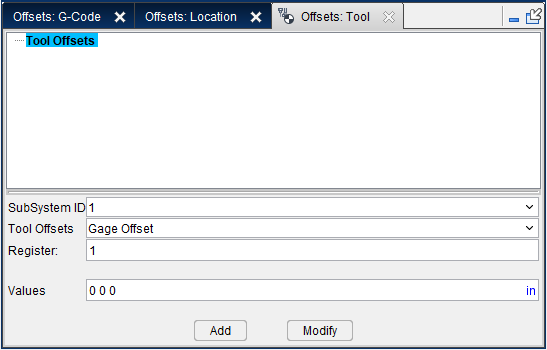
SubSystem ID — Use to specify ID of the machine subsystem for which the table is being defined.
Tool Offsets — The Location Name that will be used by Vericut to access corresponding table data. The Location Name can be selected from the following options: Cutter Compensation, Gage Offset, Probe Offset, Tool Length Compensation, and Tool Nose Compensation.
Register — The Register number that will be used by Vericut to access corresponding table data. The Register number may correspond to an offset register number, or an integer value, as required by a particular table.
Values — The Values field allows you to enter the value of your desired Work Offset.
Add — The Add feature is used to add the Work Offset to the table once all other values have been set.
Modify — The Modify feature is used to change the Work Offset in the table after it has already been created.
Adding, Modifying, or Deleting Tool Offsets Tables
To add a new Tool Offsets table:
-
In the Configure Tool Offsets group of the window, select the desired table type from the Tool Offsets pull-down list.
-
Select the SubSystem ID from the pull-down list of the machine subsystem for which the table is being defined..
- Enter the register value in the Register: text field that will be used by Vericut to access the corresponding table data.
- Enter the sub register value in the SubRegister: text field that will be used by Vericut to access the corresponding table data.
- Click on the Add button to add the table to the Tables List. Notice that the selected table and a default table record have been added to the Tables List.
- If you are creating a Cutter Compensation or Tool Length Compensation table, enter the cutter compensation, or tool length compensation, offset values in the Value: text field.
If you are creating a Gage Offset or Tool Compensation table, enter values representing the gage offset or the tool nose compensation offset in the Values (XYZ): text field.
If you are creating a Probe Offset table, enter values representing the probe offset in the Values (XYZ-X-Y-Z) text field.
Add an additional table record:
-
Select the SubSystem ID from the pull-down list for the table record that you are adding.
-
Enter the register value in the Register: text field for the table record that you are adding.
- Enter the sub register value in the SubRegister: text field for the table record that you are adding.
- If you are creating a Cutter Compensation or Tool Length Compensation table, enter the cutter compensation, or tool length compensation, offset values in the Value: text field.
If you are creating a Gage Offset or Tool Compensation table, enter values representing the gage offset or the tool nose compensation offset in the Values (XYZ): text field.
If you are creating a Probe Offset table, enter values representing the probe offset in the Values (XYZ-X-Y-Z) text field.
To modify an existing table record:
-
Click on the table record, in the Tables List, that you want to modify.
-
If you are creating a Cutter Compensation or Tool Length Compensation table, enter the cutter compensation, or tool length compensation, offset values in the Value: text field.
If you are creating a Gage Offset or Tool Compensation table, enter values representing the gage offset or the tool nose compensation offset in the Values (XYZ): text field.
If you are creating a Probe Offset table, enter values representing the probe offset in the Values (XYZ-X-Y-Z) text field.
To delete a table record from the Table list:
Right click on the table record, in the Tables List, that you want to delete and then click on the Delete button that displays to delete the table record.
To delete a table from the Table list:
Right click on the table, in the Tables List, that you want to delete and then click on the Delete button that displays to delete the table record.
All table records associated with the deleted table are also deleted.