Section window
Locations:
Project Tree > Setup Branch Right Mouse Shortcut Menu > Section
View tab >  (Section)
Toolbar short cut: ![]()
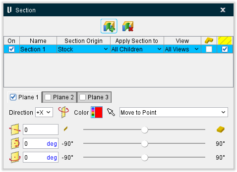
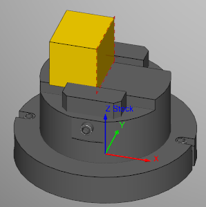
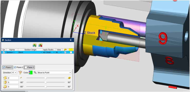
The features on the Section window enables you to define section planes through a Vericut model in a workpiece view. You can also define a section wedge through a Vericut model in a workpiece view.
You can Section with any (reasonable) number of Planes and Wedges, in any orientation. Section plane and section wedge orientation and distance are described with respect to the active coordinate system.
Restore the original model by toggling the section view off (not checked) or by clicking the Max button on the Distance slider of the Section window. You can continue cutting on the sectioned model, or restore the original (un-sectioned) model. Machine cuts are applied to the entire model regardless of how it is displayed after sectioning.
 Create New Section Plane — Produces a new section plane in the Section window.
 Delete Selected Section Plane — Removes the highlighted section plane from the Section window.
Section table
On — Toggle this feature on (checked) to display the section in the View window.
Name — Use this field to edit the name of the section.
Section Origin — Use this pulldown menu to specify the origin point of the section plane.
Apply Section to — This pulldown menu is used to specify what objects are sectioned. The options are:
-
All Children — sections all components beginning with the chosen component, and all children attached to it.
-
Self Only — sections only the chosen component.
-
All Components — sections all components.
-
All Stocks — sections all and only “Stock” type components.
View — Use this pulldown menu to determine which View windows the section will be displayed in. All Views is the default.
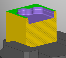
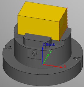
Wedge — Toggle this feature on (checked) to change the section plane into a section wedge. Wedges are formed at the intersection of two or more section planes. Rather than each section plane removing all material, once Wedge is toggled on (checked) the section planes will act as if they stop at the point where they meet rather than continuing through. For instance, in the picture below, if the Wedge option was not on, there would only be ¼ of the stock shown as the other ¾ would have been removed. As you can see though, with the Wedge option on, only ¼ of the stock has been removed and the other ¾ is visible instead.
Cross-hatching — Toggle this feature on (checked) to show cross-hatching as show below.
Section plane toggles
The Section window can create up to 3 section planes per each section that is created. These individual planes can be toggled on (checked) or off (not checked) in this part of the Section window. All active section planes associated with the section event are applied or removed via the section event “On” toggle. The section plane toggles also work as tabs where the features of the planes can be fine tuned to your liking using the following features:
Direction — This pulldown menu controls the section plane orientation and direction, and which portion of the section object(s) is removed. Directions are relative to origin of the Component selected in the section table. Options for orientation include: X+, X-, Y+, Y-, Z+, and Z-.
Flip Plane — This feature reverses the section direction and removes the opposite portion of the section object(s).
Color — Use the Color Palette icon to specify colors for Section.
The right side of the  (Color Palette) icon shows the current color of the entity. To change the color of the entity, click on the (Color Palette) icon to display the color palette window shown below.
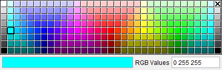
Click on a color in the color palette window, to specify the color for the entity. The color palette will close and the right side of the  (Color Palette) icon will update to reflect the selected color.
To close the color palette window without changing the color, click on the  in the upper right corner of the color palette.
Pick a point — Clicking the Selection Arrow activates the chosen mode to be used on subsequent section selections. Selection modes are modal, used for repeated picking until a different mode is chosen. Exit selection mode by choosing the selection arrow again, or closing the Section window. The following selection modes are available:
-
Move to Point — applies current section plane/orientation through point selected on a model.
-
Move to Point and Rotate to Normal — as above, plus orients the section plane to be normal to the selected model surface.
-
Move to Vertex — applies section plane/orientation through a vertex point selected on a model.
-
Move to Vertex and Rotate to Normal — as above, plus orients the section plane to be normal to the selected model surface.
-
Align to Parallel Axis — defines section plane to pass through (2) selected parallel cylinder/cone axes.
-
Move to Axis — defines a section plane that passes through a selected cylinder/cone axis.
Distance slider — This slider controls distance based from the origin of Component selected in the section table. Section plane distance can be quickly adjusted using the corresponding slider, or by entering a value in the number field. Section plane distances are limited to the extent of the objects they are sectioning.
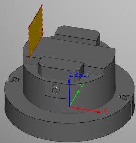
- Max — this icon at the far left of the Distance slider to produce the greatest section possible. Only a thin sliver of the material will be left visible as shown below.
- Min — this icon at the far right of the Distance slider the produce the smallest section possible. Only a thin sliver of material will be removed as shown below.
Rotation slider — These sliders control rotation based from the origin of Component selected in the section table. Section plane rotation angle can be changed using the corresponding sliders, or by entering values in the corresponding number fields.